
Assembly and Finish
This section deals with an assortment of fitting and finishing jobs, leading up to final assembly, that don't really belong to any particular part.
Crankcase
2010-10-23 – Main Bearing Housing
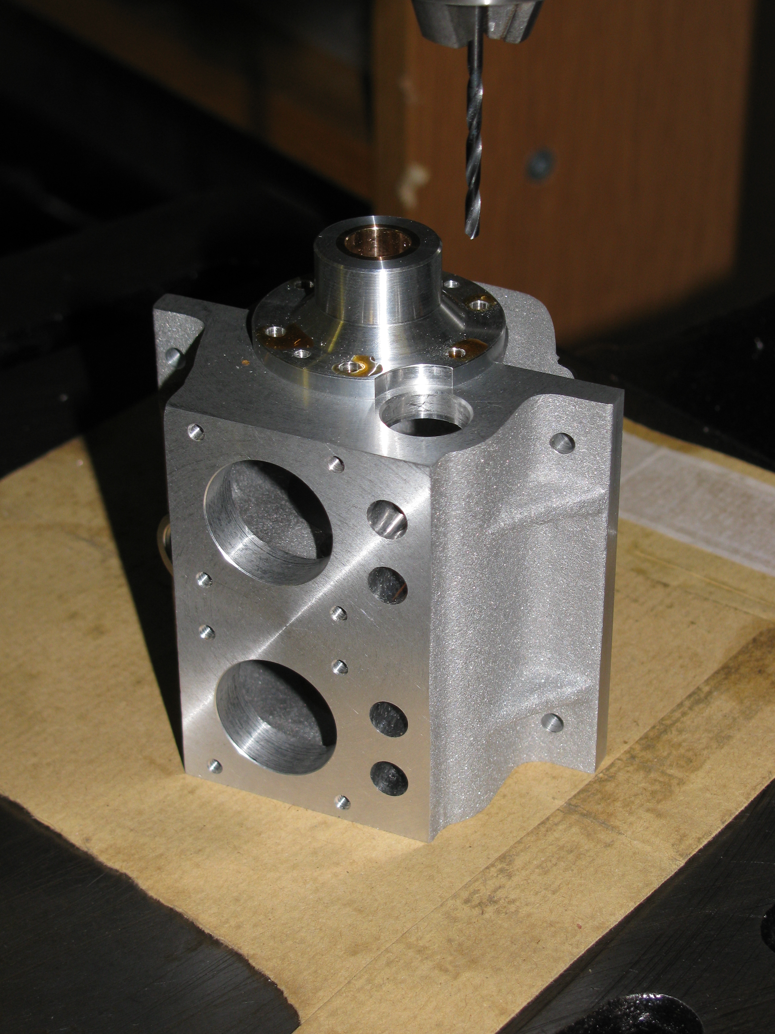
I made a bush to align the cut-away in the main bearing housing with the camshaft hole. I used it to get the right position while tightening the sump bolt which hold the bearing housing in place firmly enough to allow it to be removed for spotting the holes through. After drilling, I tapped the six holes using the pillar tool to guide the tap. (1½ hrs)
2010-11-07 – Timing-End Bearing Housing & Lapping
Using the scrap timing end camshaft bush for alignment, I spotted the hole positions through to the crankcase and sump, and drilled and tapped as before and cut down a pair of 6-BA socket cap screws to the required 9⁄32″ overall length for the two extra holes by the camshaft.
Before starting work on fitting the crankshaft bearings, the end faces of the crankcase and sump assembly need to be checked and if necessary lapped flat and square to ensure that both bearing housings sit in their final positions. For lapping these faces I used 400 or 800 grit wet-or-dry paper (can't remember which) taped to my granite surface plate, with paraffin (kerosene) as a lubricant. First, I lapped the top face parallel with the sump joint face to provide a datum. It will still need a final rub before fitting the cylinders, even though the overall height is now 3 thou undersize. Moving to the timing-end face, the sump face was very slightly high, even with the main bearing housing bolted up tight. I lapped this face flat and square. Although the flywheel end blued up square and not far off flat, I still lapped that too, although largely to look right. The resulting smooth, slightly matt surface looks so much better. Next job: lapping the bearings. (2 hrs)

Timing Case
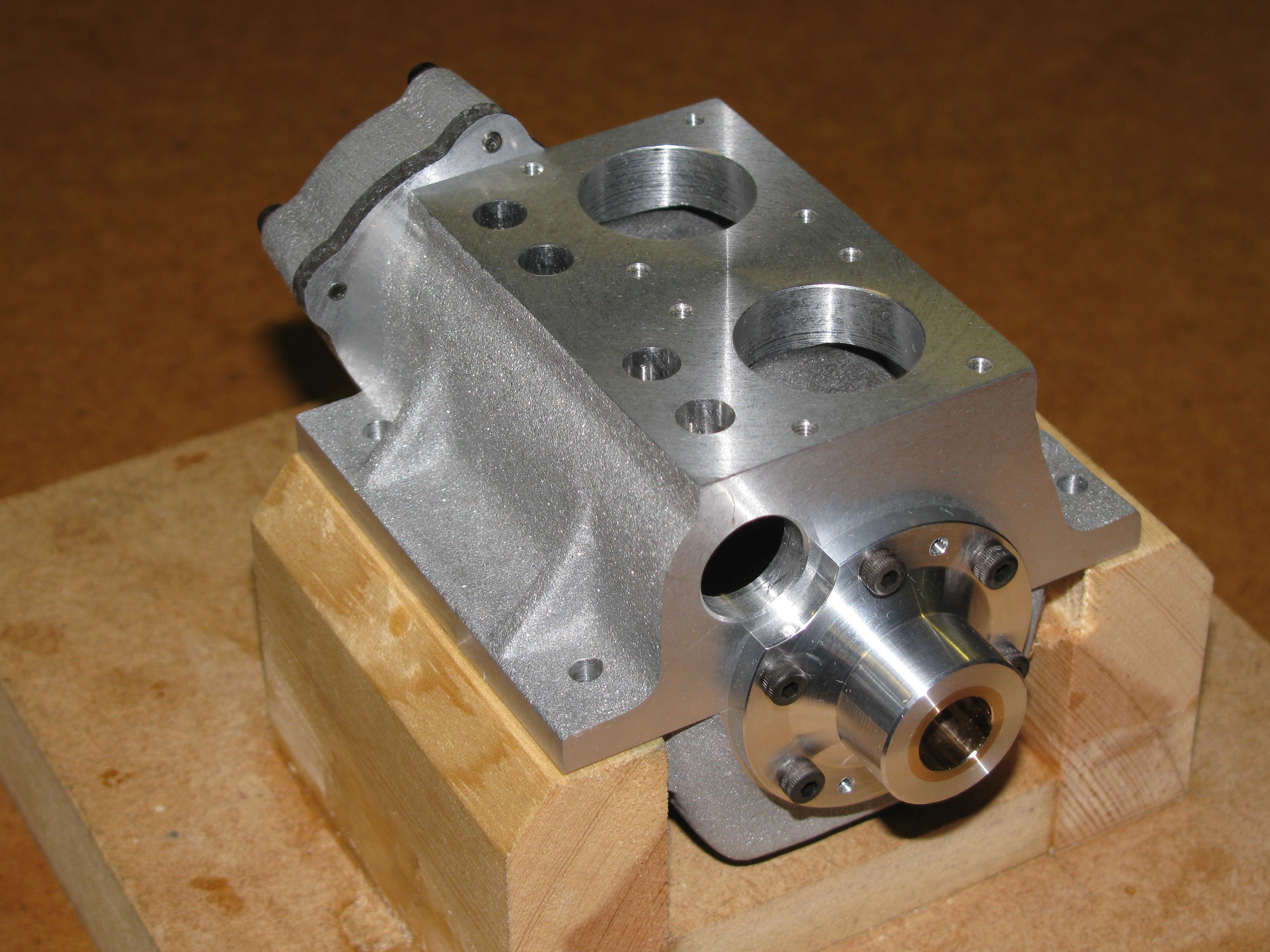
2011-12-21 – Trial assembly
With Timing-End Bearing Housing and Timing case full machined, and the Idler Stud made, it was was time for a trial assembly. Trying the gears, the crankshaft pinion and idler ran were good but the idler and camshaft gear have come out quite a bit too tight. This will need further work. The fit of the timing case depends on the dowels, the idler stud and the crankshaft sleeve, and it is not surprising that this will not go together comfortably without fitting work. (1 hour)
2011-12-30 – Easing
Having pushed the timing case home I found I needed to warm it up almost too hot to hold before it would come off in the hand. I also need to put tapped forcing-screw holes in the bearing housing to make it easier to dismantle without having to slacken the sump securing bolts as well. I refitted the idler stud in its chucking bush and polished it until it went fully home with a shake-free easy push fit, but the stud and dowels are still in conflict. The fit is free until it the case is almost home, and carefully easing the hole a little with a hand reamer makes for an easier fit. (1¼ hours)
2011-12-31 – Assessment
The crankshaft sleeve turns sweetly in the timing case. The assembled crankshaft and sleeve turn with a half-turn a little stiff when running in the timing-end main bearing and timing case. Fully assembled, with a full set of bolts holding the timing case in place, there is some stiffness, but I think it will bed in OK. The idler pinion was also stiff on its stud when home to the shoulder. This was soon cured by polishing over the oil hole in the stud with 1200 grit wet-or-dry paper. The gear train will have to be investigated further, as it is too tight to expect it to run. (2 hours)
Bead-blasting
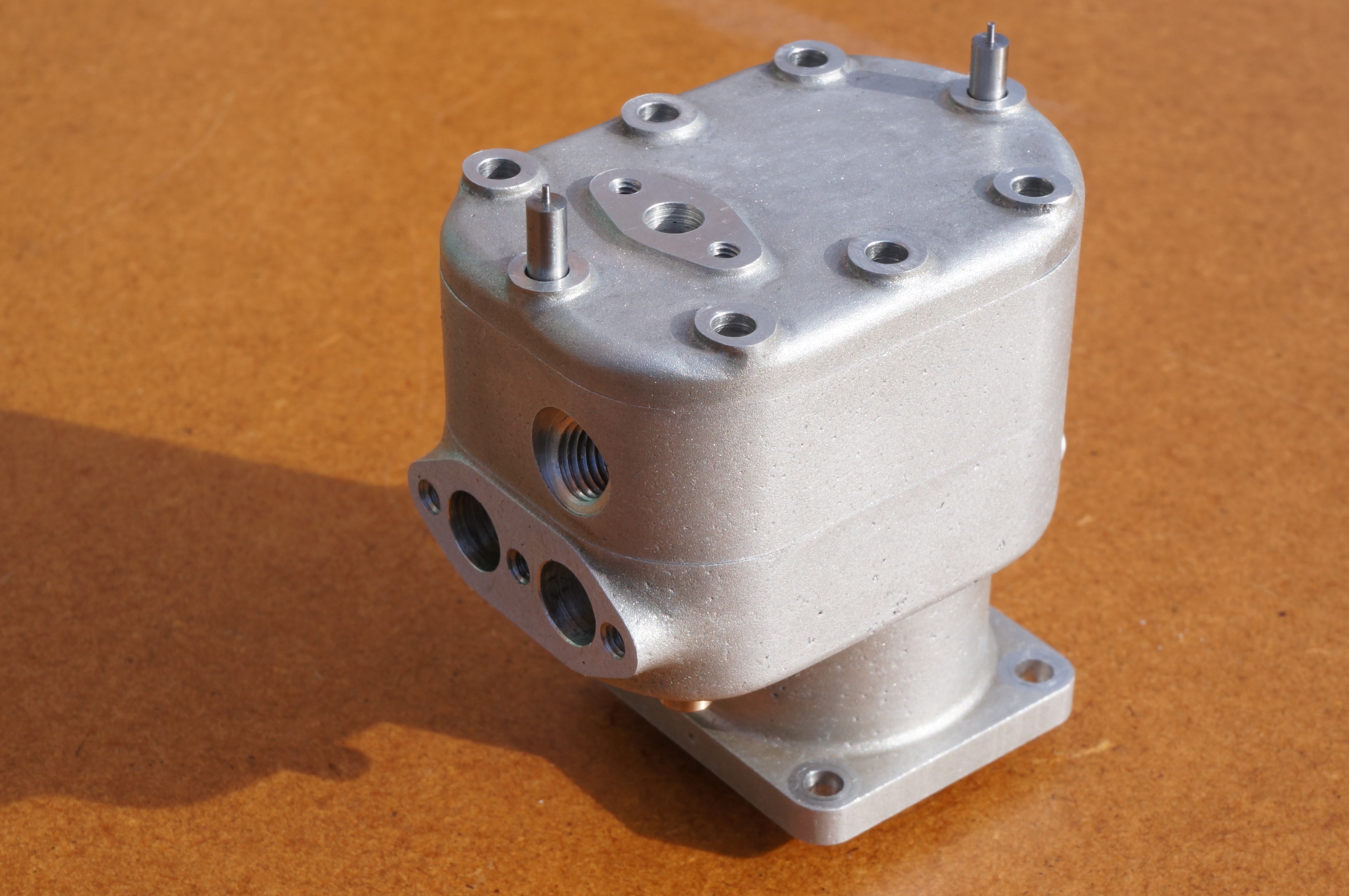
2015-03-04 – No 1 Cylinder assembly
After trimming 6-BA cap-heads to fit, I prepared No 1 Cylinder assembly for blasting by blanking off all the exposed machined bits. Straight out of my new blasting cabinet, the result looked nasty because of staining from porosity, mainly of the cylinder casting. Given a paraffin (kerosene) wash, a hot soapy water wash, and a wipe with light oil, it looks a lot better and blends in with the crankcase parts similarly finished some time ago. (2¼ hours)
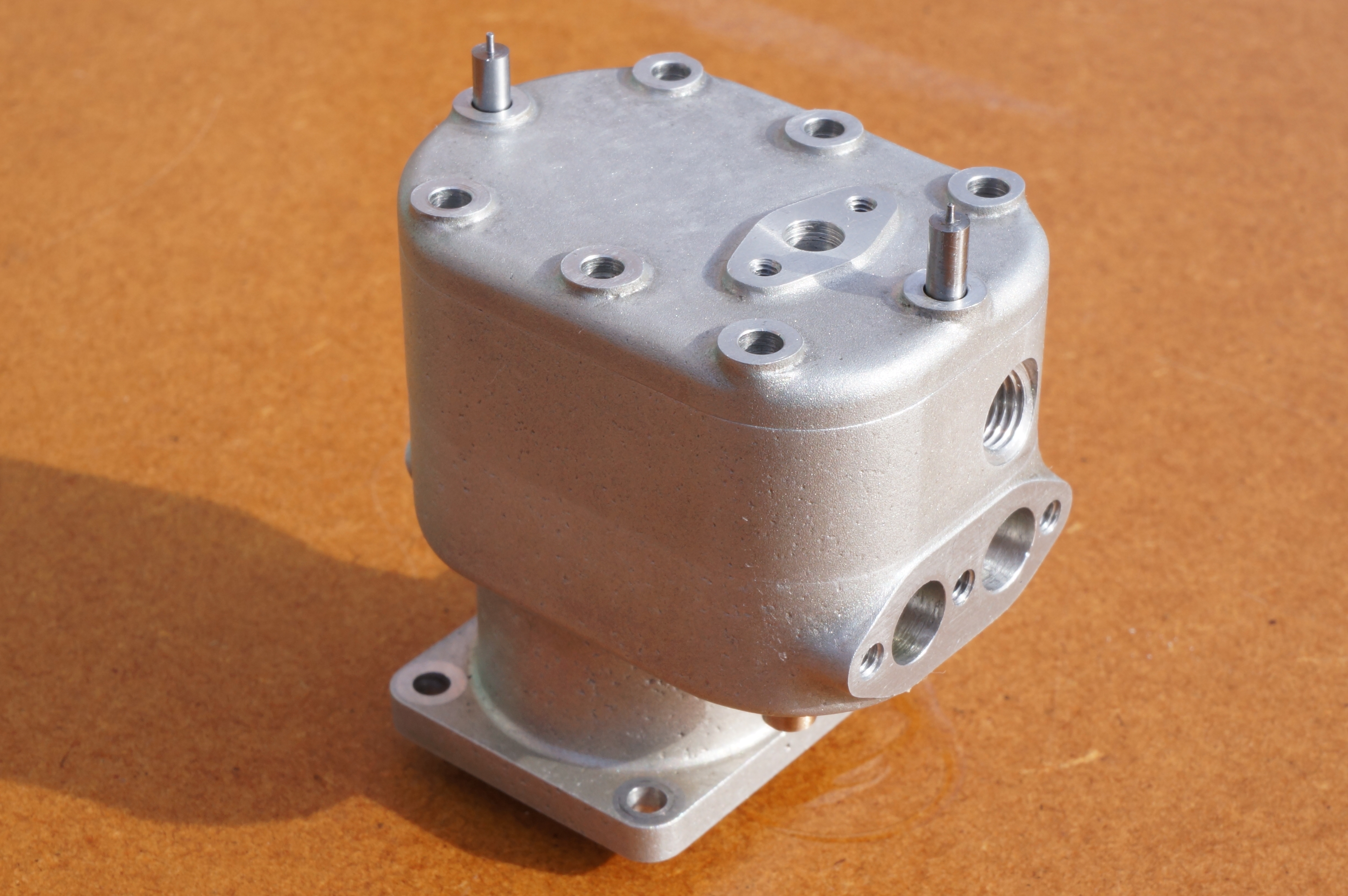
2015-03-05 – No 2 Cylinder assembly
Today I went through the same procedure with the other cylinder. (1¼ hour)
Lapping
2015-03-06 – Lapping the manifolds
As a diversion from making tiny studs, I spent a little time lapping the main joint faces of the mainfolds, using 600 grit silicon carbide paste on a glass plate. After carefully cleaning up, I tried the inlet manifold on the surface plate. It blues up perfectly with with a very thin smear. (1 hour)
A first look
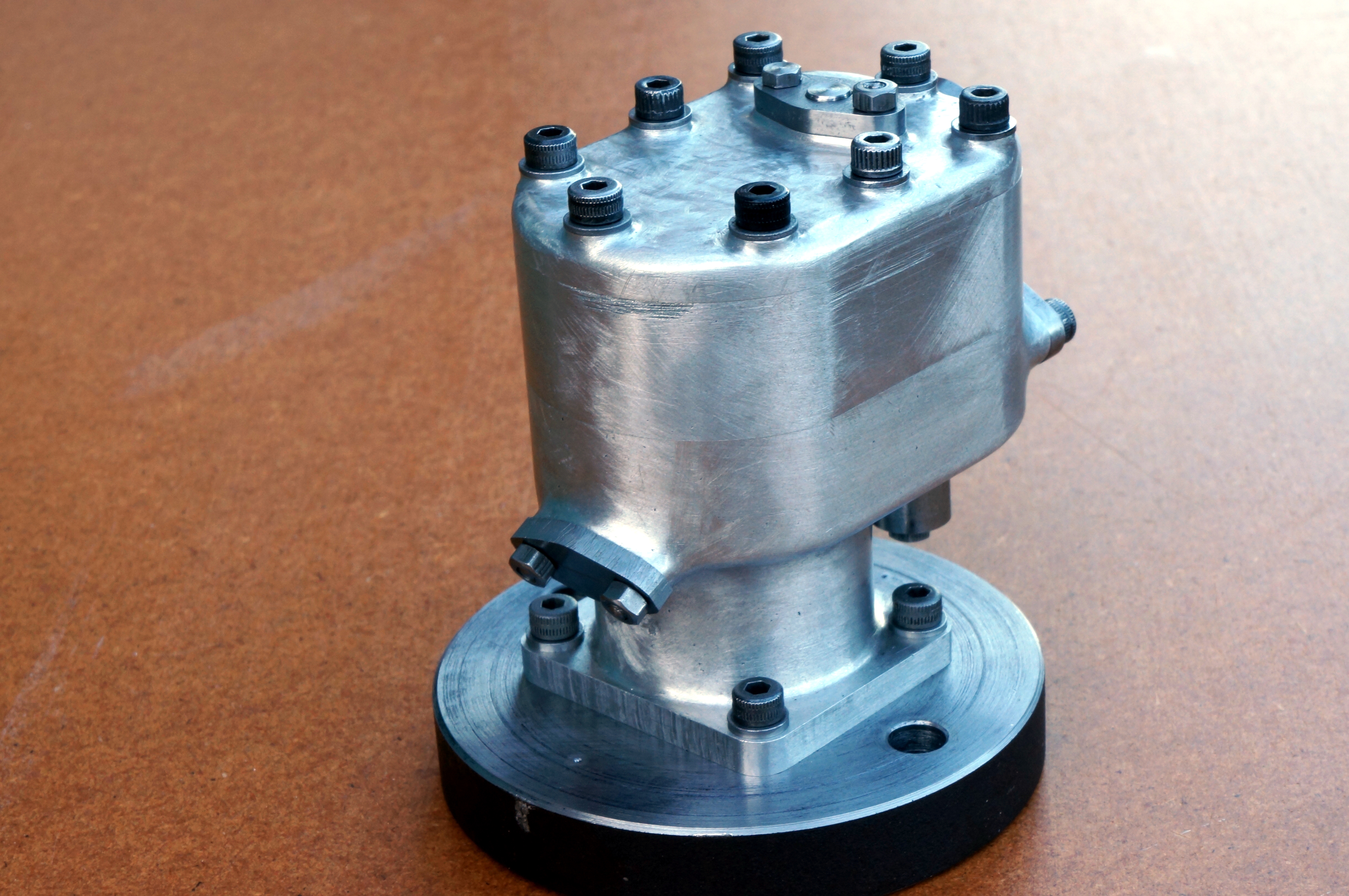
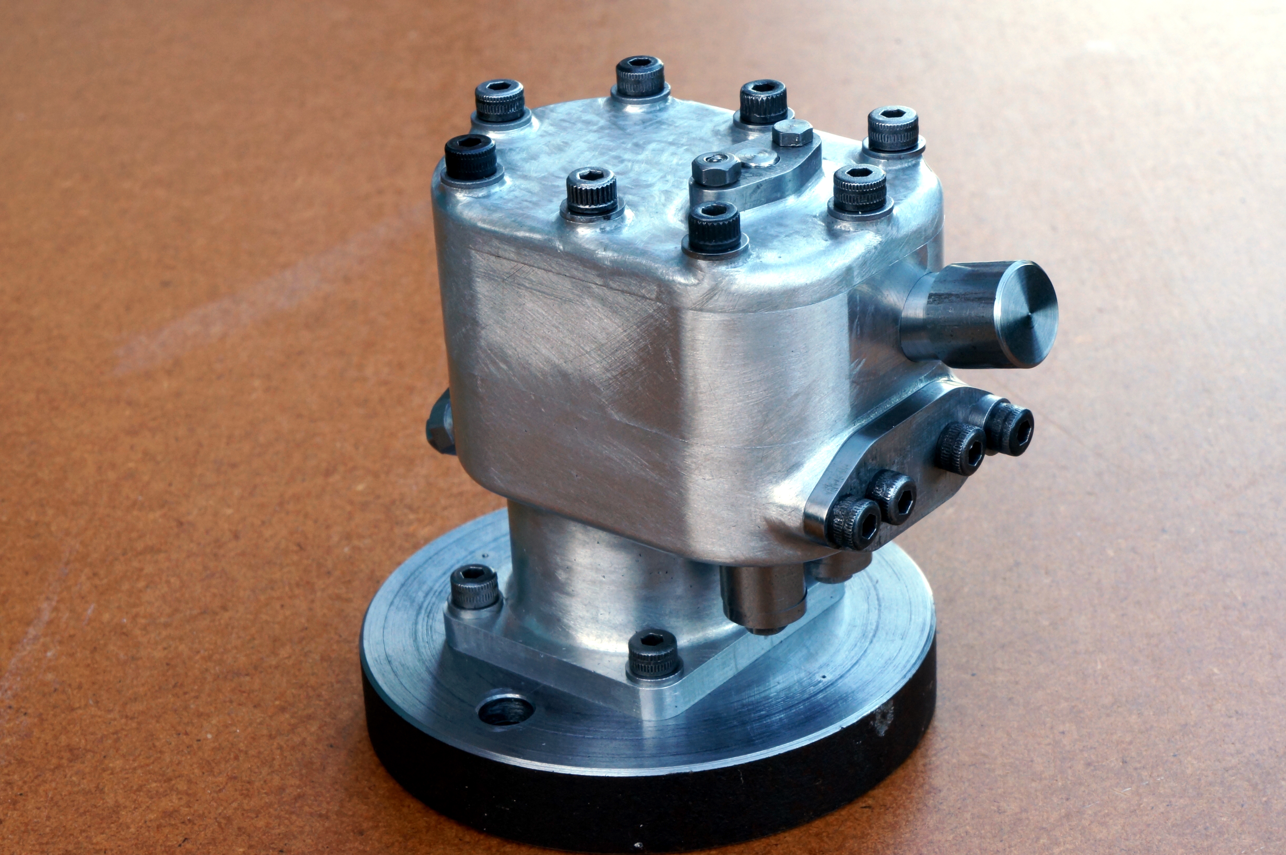
2015-03-21 – Studs and washers all made
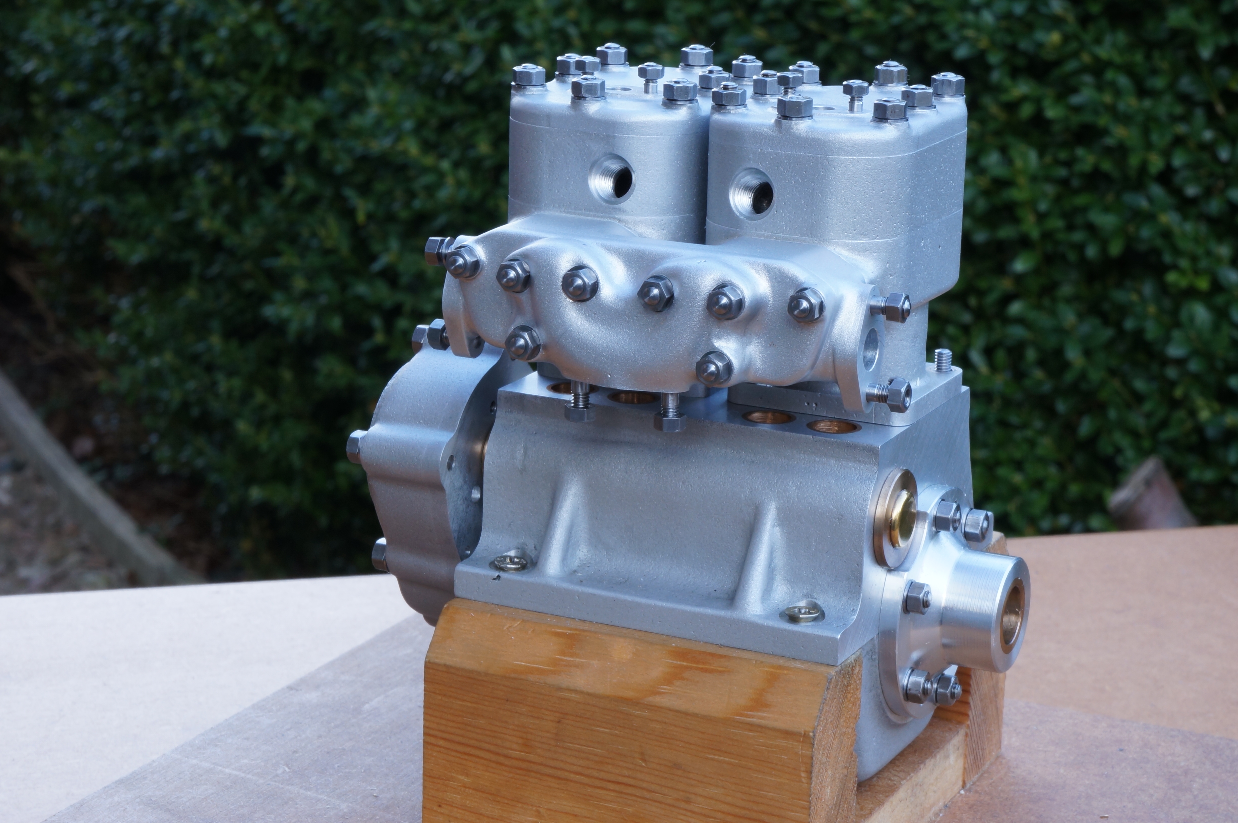
With all the castings (except the carb body) finished, fettled, and sand blasted, and all the studs and washers made, I thought it was time to go for a trial assembly to see how it all looks. This was just the castings, I did not put any of the moving parts inside. The timing case is not pushed fully home. I think the apparent unevenness of the head studs, which are individually measured, is largely down to variability in the thickness of the commercial nuts. For the inlet manifold I have used some more recently bought nuts that are 6-BA with a 7-BA hexagon: washers for the standard size would have overlapped the casting.
.
Full Build
2017-03-20 – Assembling a short engine
To start with, I lapped the cylinders on the port faces and tops. I lapped both cylinders to 1.255″ height, which compensates for the slightly undersize crankcase and still allows an extra couple of thou for any subsequent re-working. I washed the cylinders twice in paraffin and once in hot water, blowing out with compressed air at each stage, and then oiled the liners. The water wash showed up the extent of the porosity in the castings.
With this lapping done, I now have final valve seating faces, so I had a play around with seating the valves. I tried burnishing each valve on its seat, using the spring retaining nuts to twiddle the stems and with finger pressure on the heads. With No 1 inlet, I tried a little Brasso, carefully so as not to lap the valve guides. I am unconvinced. There is a tiny bright edge on the seats, but I think the process may be more likely to score the valves. I will know more action is needed when I find I cannot get any compression.
The crankcase is already assembled, so I stripped it down. I found a little black debris at the timing end bearing of the camshaft, but otherwise it was pretty clean.
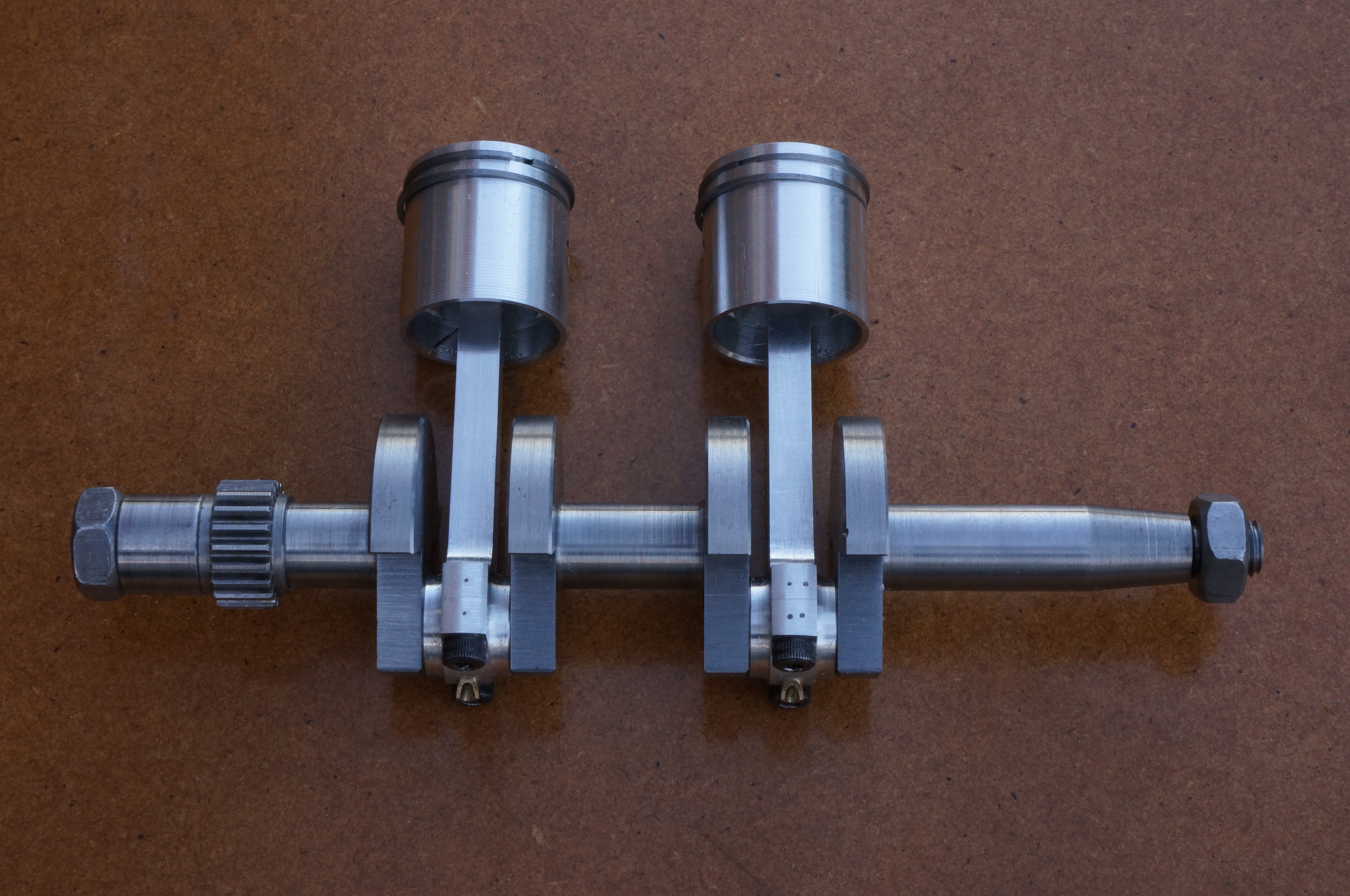
I fitted the rings to No 1 Piston, ring 1 a the bottom and 2 at the top, and tried the assembly in the bore. I found this job scary at first, but by the time I had No 2 assembled (3 bottom, 4 top) I was feeling quite blasé about it.
After washing the crankcase and sump I fitted the crankshaft by the centre bearing. I concluded there would be no way to wiggle the valve springs and nuts into place after fitting the cylinders to the crankcase, so the valves have to be assembled first. I also decided I did not like the idea of pushing the cylinders over the piston rings, so I split the big ends and put the piston assemblies into the cylinders. I fitted the cylinders with Hylomar on the flanges, which continues to squeeze out as the nuts are re-tightened.
Continuing in the evening, I fitted the sump, front bearing cover, and camshaft. I checked the orientation and tightness of the idler stub shaft in the timing plate and fitted that, with the two extra countersunk screws by the camshaft bearing. Next I fitted the timing gears and camshaft nut, and the timing case. Finally I fitted the spacer bush, the flywheel, and both crankshaft nuts. With the nuts tightened, I decided to fit the drive coupling to the flywheel.
It all turns over without binding, but it is rather stiff. Unfortunately, I have no photo of the engine at this stage. (5¾ hours)
2017-04-01 – Adding Heads and Manifolds
After cleaning off the residue of Hylomar extruded from the cylinder flanges, I checked the pistons at top dead centre. No 1 is 0.0036″ below the cylinder top face and No 2 is 0.0050″. As the theoretical figure is 0.0037″ I am not displeased. I also made sure the combustion chambers cleared the valves.
I lapped No 1 cylinder head, having some difficulty getting the top and bottom faces truly parallel and making sure they blued up well on the surface plate. It ended up +0.0002 to +0.0008 thou on nominal.
The head studs have individual positions and have previously been adjusted for even length. With a a little graphite grease in the holes, I screwed the studs in using a No 0 Jacobs chuck to drive them tight. One stud proved to be a trace low and I slackened it off a little. The Cover had previously been finish lapped, so with Hylomar brushed on both joint faces, I assembled the head, again with a little graphite grease on the studs and plug hole. I fitted the plug. Compression: none.
After lunch, I checked the tappet clearances, re-tightened and cleaned off the extruded Hylomar. Still no compression. Moving on to No 2, I lapped the head to +0.0011 to +0.0015 thick. The chuck trick could not be used for the studs nearest No 1 cylinder. By putting some oil down the ports, there is a little compression, with more on No 2.
I want to use the leftmost manifold stud for a clip to hold the plug leads, so I made a new longer stud. I cleaned, greased and fitted the manifold mounting studs and the two for the carb. With the cylinder mounting nuts backed off, I fitted the manifolds and tightened the nuts before retightening the cylinders.
Moving on to the timing ring, I finished the angular locating dowel and Loctited it into the ring. However, with the dowel in place the ring would not go onto its spigot on the timing gear. I knocked the dowel out again and scraped the bore of the timing ring until it would fit. The heads of the countersunk screws holding the timing ring are proud of the face. This will need adjusting to provide the necessary clearance for the hall sensor. (6½ hours)
2018-08-11 – Making a valve seat cutter
Today I made a nice little valve seating cutter, and gave it a tentative trial. I removed No 2 cylinder head and laboriously removed the exhaust valve. There seems to be contact all round the seat, but perhaps not all round the valve. I tried the cutter gently and briefly, and it looks as if it will work, but still needs hardening. I reassembled everything. Unsurprisingly, as yet there is still no compression to speak of. (3 hours)
2020-02-19 – Seating the valves
Having decided to try Wellseal as a joint sealant instead of Hylomar, I stripped the engine down, and cleaned it with with acetone. While it was apart, I made a shallow recess in the top of the sump drain plug to receive a little magnet intended to collect any ferrous particles in the oil. On reassembly I had to slacken the sump nuts to get the timing plate home, tightening them again afterwards. The camshaft has a tight spot, which is probably a lack of end float.
The other reason for the strip down is that I want to attend to the valve seats to see if I can improve the compression. I think this will be necessary to get the engine to run, but right now I am testing starter motor options, and I need some decent compression to load the motor realistically. I used the valve seat cutter, which has now been hardened, to make a seating less that 0.010″ wide on No 1 cylinder, and then gently ground the valves in with 600 grit silicon carbide paste. Note to self: 0.0025″ valve clearance should require 47° of nut rotation. (about 7 hours)
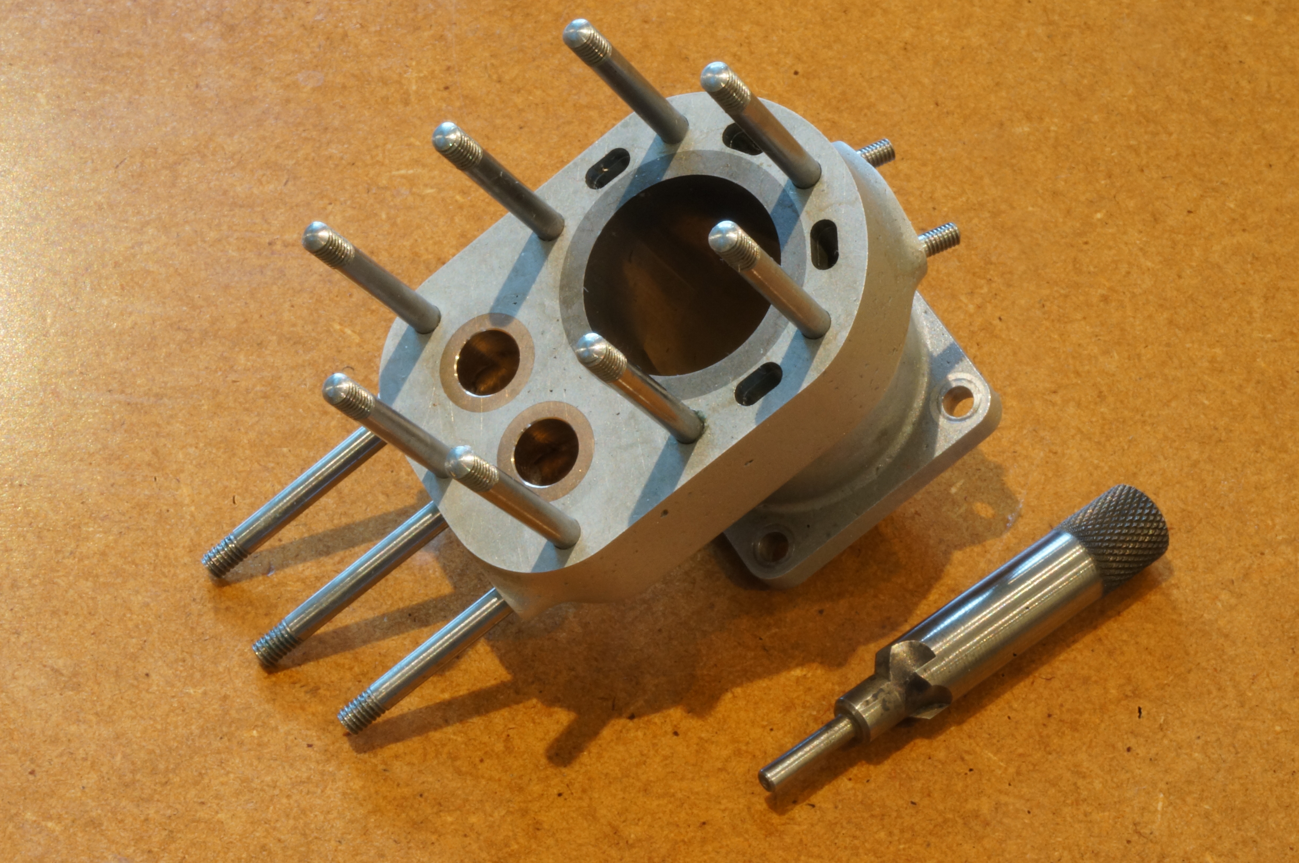
2020-02-20 – Finishing the assembly
This morning I dealt with the valve seats for No 2 cylinder. The photo above shows the cutter and a fine, bright cone on each valve seat. I completed the assembly with the heads, carburettor and silencer in the afternoon. I did not fit the coolant pipes. We are now ready for a compression test. (about 5 hours)
.