
Camshaft
Material and construction
Westbury suggests a one-piece case-hardened mild steel camshaft, or alternatively a bit of scrap alloy steel left in the found condition. Hemingway supply a piece of ½″ silver steel (drill rod) which I think they intend to be left soft. Other writers favour a built-up camshaft with cams fixed with Loctite. This has the advantage that different materials can be used for the shaft and the cams.
If a solid mild steel camshaft is case hardened then the cam profiles should be completed and carburised but not hardened, so that the rest of the shaft surfaces can have the case machined away. The job is then re-heated and quenched to harden the cam surfaces. Finally, the soft parts can be finish machined. A fully hardened silver steel shaft would be far too short: the ends, particularly the taper and thread would need to be thoroughly tempered, but without letting down the cams. Either way, a certain amount of distortion is highly likely. Built-up construction avoids all these problems, but does present a different one: alignment of the cams during assembly.
I intend to make a built-up camshaft, but rather than individual cams, I intend to make a joined pair for each cylinder. These will be hardened silver steel. The camshaft will be made from high tensile steel.
Ignition timing
After drawing several layouts for mounting a carrier plate for the ignition sensor magnets to try to get a compact arrangement, I finally decided to make this as a ring attached directly to the timing gear. This enables a short camshaft to be used with the gear retaining nut inside the ring.
Cam design
Before I come over all analytical, this needs to be kept in perspective. This is a small side-valve engine intended for modest speed and performance: unless there are silly errors the acceleration forces in the valve gear will be very low. Secondly, an interesting exercise I have yet to perform is to see how accurately I can set out the cams using the pencil and paper methods available to Westbury. Thirdly, a stack of these engines, particularly the Seal, which has identical valve gear, have been built successfully, probably mostly without modification. Having said that, I have looked at the design and I do find things are not quite right, so I am hardly going to plough on regardless. I would like to achieve silky smooth operation of the valve gear, to minimise noise. I use cam angles, not crankshaft rotation, throughout this discussion.
| Cam specification | ||
|---|---|---|
| Inlet | Exhaust | |
| Base Radius | 11⁄64 | 11⁄64 |
| Flank Radius | 9⁄16 | 9⁄16 |
| Lift | 5⁄64 | 5⁄64 |
| Opening Angle | 120° | 130° |
| Nose Radius | 1⁄32 | 5⁄64 |
Westbury does not give much detail about the cam design and manufacture in the Seagull articles, referring readers to the prior series on the Seal, and it is necessary to read the relevant parts to get the full picture.
The first thing you find when trying to reproduce the cam design with CAD is that the given dimensions don't work.
With the given base circle diameter, flank radius, angle, and lift, the noses come out too small, at pretty close to 1⁄64″ for the inlet, and 1⁄16″ for the exhaust, amounting to 1⁄64″ undersize in each case. The resulting profile of the inlet cam just looks too sharp. This exacerbates a problem with the tappets, which I discuss below. Any of the parameters can be altered to adjust the nose radius. Curiously, I have found geometric constructions for all of them, except for finding the nose radius given everything else. I have, however, found a simple trigonometrical solution for that case.
Corrections
The figures below are the result of my geometric constructions using Autosketch, quoted to 4 places. By increasing the flank radius to 5⁄8″ both nose radii come within a few thou of the design figure. For exact nose radii, the flank radii should be 0.6211″ and 0.6633″ for inlet and exhaust respectively. The construction for finding the radii is a bit more difficult and it would be harder to get it accurate on a drawing board as it involves finding the intersection of two straight lines that are at a small angle. Increasing the opening angle by 2.8° for the inlet and 3.8° for the exhaust also does the trick. The geometry for this is quite easy. Reducing the lift, by 0.0044″ to 0.0737″ and by 0.0064″ to 0.0717″ respectively is another option, the easiest construction of all. Finally, the base circle could be increased, a method which would also effectively reduce the lift. The radial increments are 0.0037″ and 0.0046″ this construction was also a piece of cake, once I had worked out how.
Using Westbury's method of turning the flanks and then filing the nose radius to a gauge would seem to come nearest to the reduced lift solution. I need a bigger nose radius on the inlet cam to get over the tappet size problem and am going for a slight increase in the inlet cam angle to 122°, combined which a reduction in lift of 0.002″ which together give a nose radius of 0.0335″. I will leave the exhaust cam with the slightly undersize nose radius as designed, as this one is not a problem. This alteration allows me to retain the design flank radius, which gives an appropriately mild cam, keeping the acceleration and maximum velocity down. It is the velocity that determines the necessary tappet diameter. Opening the inlet valve 2° of crankshaft rotation earlier, and closing it 2° later, while losing 2½% of the lift should not make a huge amount of difference.
Tappet clearance
The base circle needs to be relieved, by 0.005″, to provide the tappet clearance. The transition between the clearance and the start of the cam flank needs a bit of thought. In the Seal articles, where Westbury describes his favoured eccentric turning method, he suggests that the relief is provided by making a series of cuts round the heel of the cam 5 thou deeper than the flank cuts, and taking them to "within about five degrees of the flank positions". If this means what I think it means, then the apparently innocuous cut of 5 thou would actually cut substantially into the start of the flank proper, resulting in reducing the valve opening by more than 11° each side, and removing an important part of the acceleration curve, causing an impact when the cam flank eventually arrives at the tappet. To avoid cutting into the flank, this treatment would need to stop at 16° from the flank start. The harshest solution is described by Ron Chernich, in which a tangent to the heel radius is taken from the start of the flank, but this would produce an odd looking sharp discontinuity on the cam surface. Actually, the flank-radius-minus-5-thou solution does just the same. Elsewhere, I have seen a description of a 'constant velocity ramp'. Playing around with this it looks as though a smaller radius at the end of the flank and then a short tangent between that radius and the clearance radius will provide what I want.
In the Seal articles, Westbury mentions that some might consider a 0.005″ tappet clearance excessive and explains that he has specified it to make allowance for the some distortion in hardening a one-piece shaft. As my built-up shaft will not suffer from this problem, I am intending to halve the clearance. This makes the design of the transition easier. I do not know what temperatures the valve stems and cylinder body will get to, but some rough calculations show the clearance is unlikely to change much as the engine reaches running temperature. Measuring the clearances with a hot engine would be good, but may not be easy.
Tappets
The design tappet diameter is too small. Even as redesigned, the inlet cam needs a tappet 0.277″ diameter, and that is the absolute minimum, momentarily reducing to point contact at the edge of the tappet at the transition between the cam's flank and nose. The radial offset, from centreline, of the contact line between cam and tappet is directly proportional to the valve velocity at that point in the rotation. To maintain line contact across the full width of the cam throughout would require a tappet about 11⁄32″ diameter. As there are places where the existing ¼″ tappet holes in the crankcase have barely ¼″ depth, and I would not like to have a tappet bearing bore shorter than its diameter, I think tappets any larger in diameter than design would need to have bushes. The bush can project into the crankcase so as to just clear the cams, and this would provide some extra support just where it is needed. The 7⁄16″ centres spacing of the tappets does not leave a lot of room between the two for bushes, though. An 11⁄32″ outside diameter bush would allow an adequate 3⁄32″ between and could be bored for a 9⁄32″ tappet. In combination with the redesigned inlet cam this is big enough to allow line contact throughout, although the line still reduces to no more than about 1⁄20″ long at the transition point.
Resources
There is an excellent analytical tool for camshaft design and generation available on Ron Chernich's pages.
There are some informative pages on cam design at Tilden Technologies
Machining methods
No doubt the ideal method would be to finish grind the hardened cams. This would require some kind of grinding machine.
Attempts at end milling to a table of offsets works well enough, but I have tried a brand new slot-drill and a single-point cutter in the form of a boring bit. In both cases the finish I obtained was atrocious.
A trial using a grinding wheel in the lathe and using the cross-slide and dividing head for offsets gave a surprisingly faceted result, though this may have been partly due to stiffness in the cross-slide. The surface finish was good. This should perhaps be tried again more carefully.
2011-04-30 – Roughing out
I find good quality bolts are a useful source of small pieces of high-tensile steel. I used a 4″ x 3⁄8″ Whitworth bolt from which I roughed out the camshaft to about 10 thou over size all over. (1½ hours)
.
2011-05-07 – Cam blanks
I parted off the two paired cam blanks and an extra bit to use as a test piece to check how the bore size comes out after hardening. In the supplied state it was very nasty to cut, as silver steel generally is. I normalized the pieces by heating to bright red and burying in vermiculite until cool.
While this was going on I made a sample tappet bush for the crankcase, 9⁄32″ bore and 11⁄32″ outside diameter, as an aid to deciding how to deal with the undersize tappet problem.
When it had cooled, I drilled, bored and reamed the cam test piece. Boring was still pretty nasty even after normalizing, but the reaming operation was OK. After hardening and cleaning up the fit was good, with a little play detectable, suitable for Loctite.
I faced the cam blanks to length and then set them up in the 3-jaw chuck with a packer, about 1mm thick, under one jaw to throw the blank off centre a little. The bar provided is ½″ diameter, which gives no machining allowance for the nose radius unless the bore is offset a bit. As the cams are 110° apart the high side can be shared between them. I centred and drilled 5.9 & 6.2 mm at 600 rpm and reamed ¼″ at 200, all with plenty of RTD compound.
The last job today was making a stub-mandrel to hold the cam blanks for machining. (3½ hours)
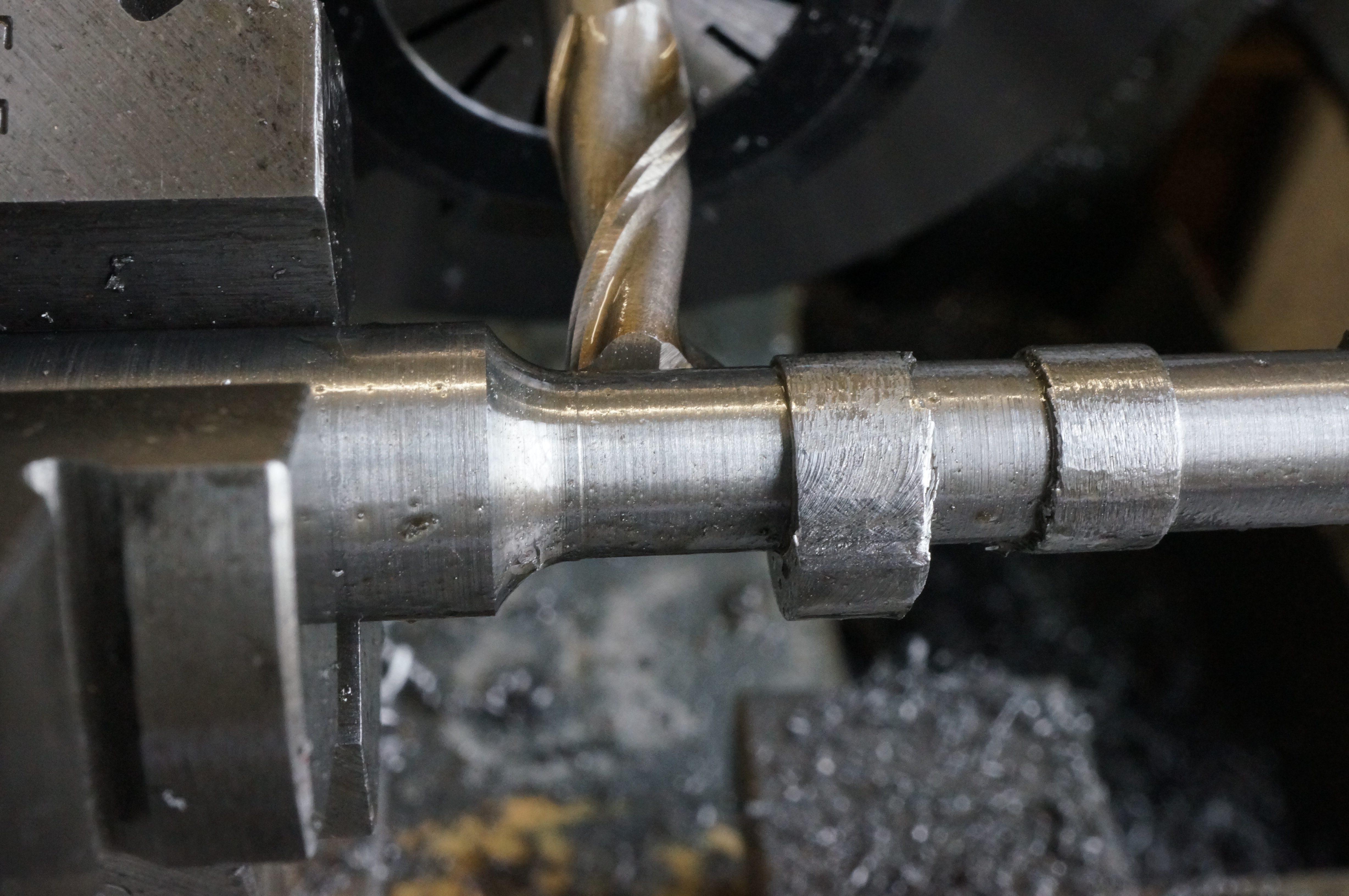
2011-05-23 – Cam blank grooves
I tried a newly obtained 8 mm square parting-tool holder for cutting the groove between the two cams. Because it holds the blade at an angle to provide a bit of top rake, it is not possible to get the tip on centre-height using my 5⁄16″ quick-change tool holders. Forgetting that I have a special for 3⁄8″ tools, I tried packing up the back end of the parting-tool holder to tilt the business end down a bit. Putting radii on both sides of such a small tool bit was not easy either, and the whole rather unsatisfactory arrangement produced a rough finish. For the second blank I altered the radii on an existing 1⁄16″ grooving tool. This also produced an awful surface, which I cleaned up a bit with a needle file.
I also made a new, longer, stub mandrel after finding the first one too short to get clearance between the chucks. (3¼ hours)
.
2011-05-28 – Milling cam profiles
Setting up for milling the cam profiles took a while. The dividing head was sitting on stacks of packers, and was not very rigidly mounted, while tightening the central bolt made the cross-slide rather stiff. I clamped a dial gauge to the bed to measure saddle travel accurately. The 3-jaw chuck was moved from lathe spindle to dividing head without removing the freshly turned stub mandrel. Armed with a table of offsets calculated on a spreadsheet at one degree intervals, I started on an easy bit by roughing out the fixed radius heel of the exhaust cam in 5° steps. I worked the tappet clearance take-up ramp one degree at a time and started on the flank. After 12° intervals I realised I was going the wrong way on the dial. So this one is scrap. I moved on to do the inlet cam for the practice. The milled finish was just diabolical. (4½ hours)
2011-06-03 – More milling
The remaining flank of the exhaust cam offered an opportunity to try to improve the surface finish. I tried using a single-point boring bit as a fly-cutter, but the result was no better.
Clearly some improvements would be needed to get cams that were even adequate. The first step was to make a proper cross-slide mounting block for the dividing head, a job that I had been meaning to do for years, and I now had a suitable chunk of aluminium in stock. (1 hour)
.
2011-07-05 – Trial cam grinding

I had decided to have a go at grinding the cam profiles, initially trying using the same incremental offset method, as this required little extra setting up, using the lathe spindle to mount the wheel. All that was required was an arbor. I decided to make one that would mount a spare 6″ wheel in my largest ER collet. These jobs took up pretty much all my workshop time for a month. For dressing the wheel the whole lathe was covered in newspaper which went straight in the bin afterwards.
I hardened the scrap cam set. It is now a bit too tight on a ¼″ ground bar, so the final ones may need lapping internally to allow a loose enough fit for adjusting the angle before the Loctite starts to set.
Because it was only a trial I did not take enough care in setting up for grinding. I used a magnet to fix the dial gauge in place and this must have shifted during the job, resulting in excessive cuts, a wrong profile, overheated work and a well-glazed grinding wheel. Although the mounting block for the dividing head was a vast improvement, the cross-slide was still stiff. Despite using one degree increments on the dividing head, even the good parts of the resulting surface still seemed to be faceted, to an extent that I had not expected.
I need to try this again more carefully, but I think it still won't give me the results I am looking for. Back to the drawing board. Meanwhile, the lathe has been used for grinding, and the next job is to strip the carriage and slides and clean thoroughly. (4¼ hours)
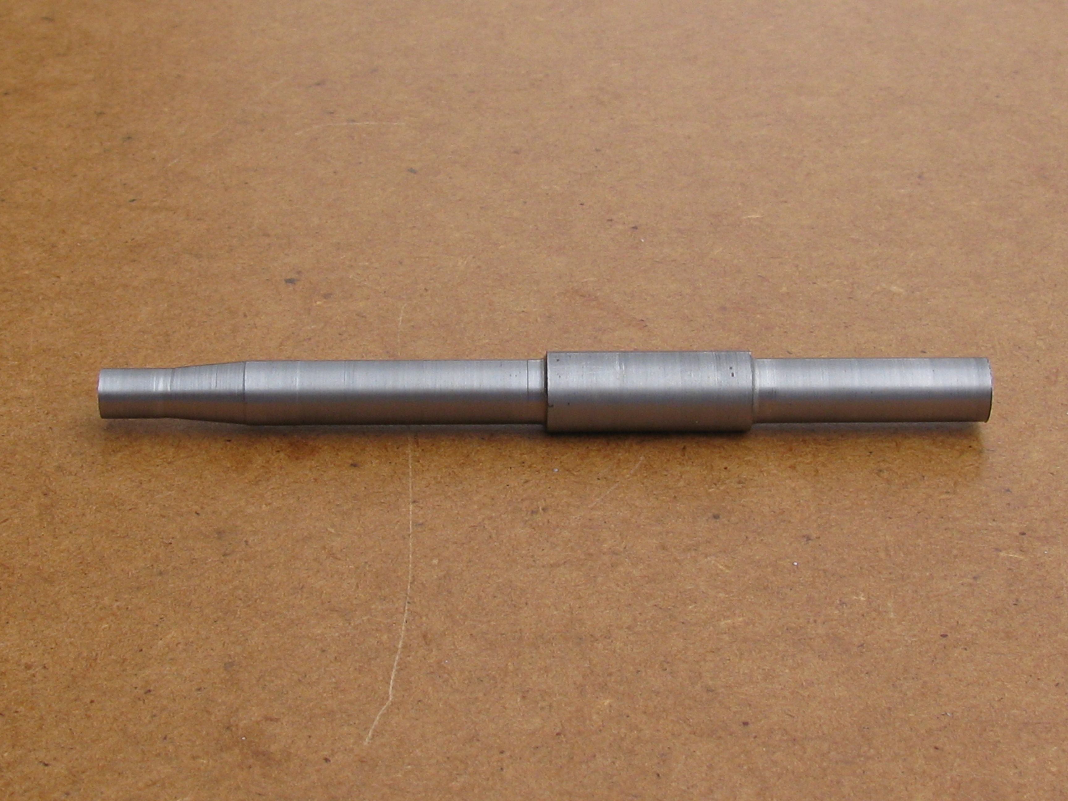
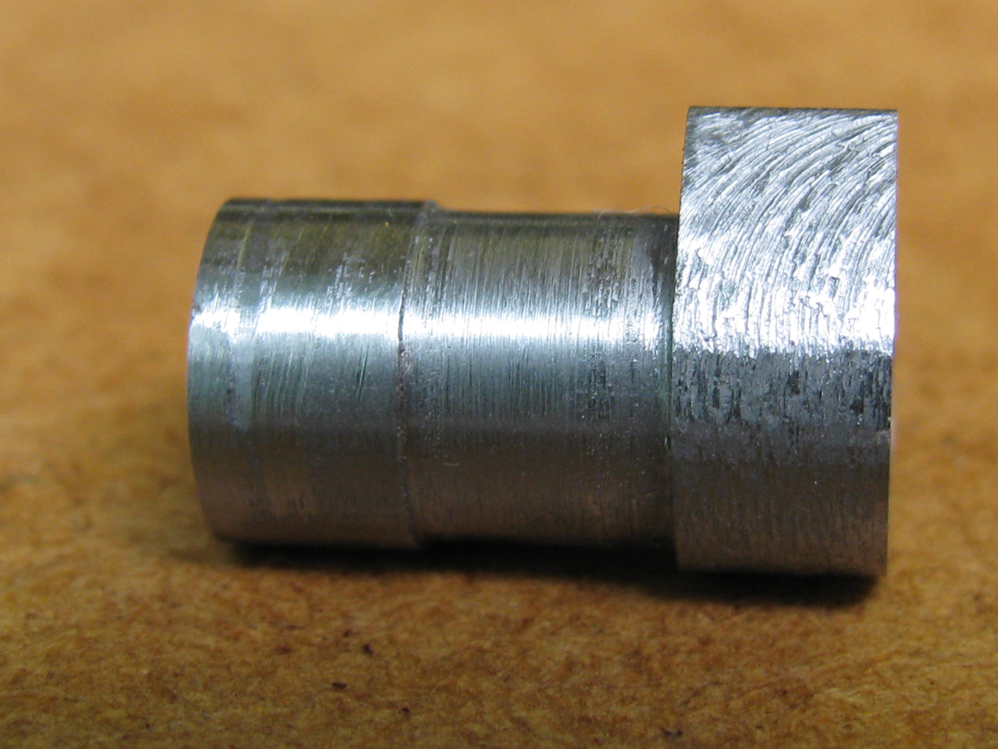
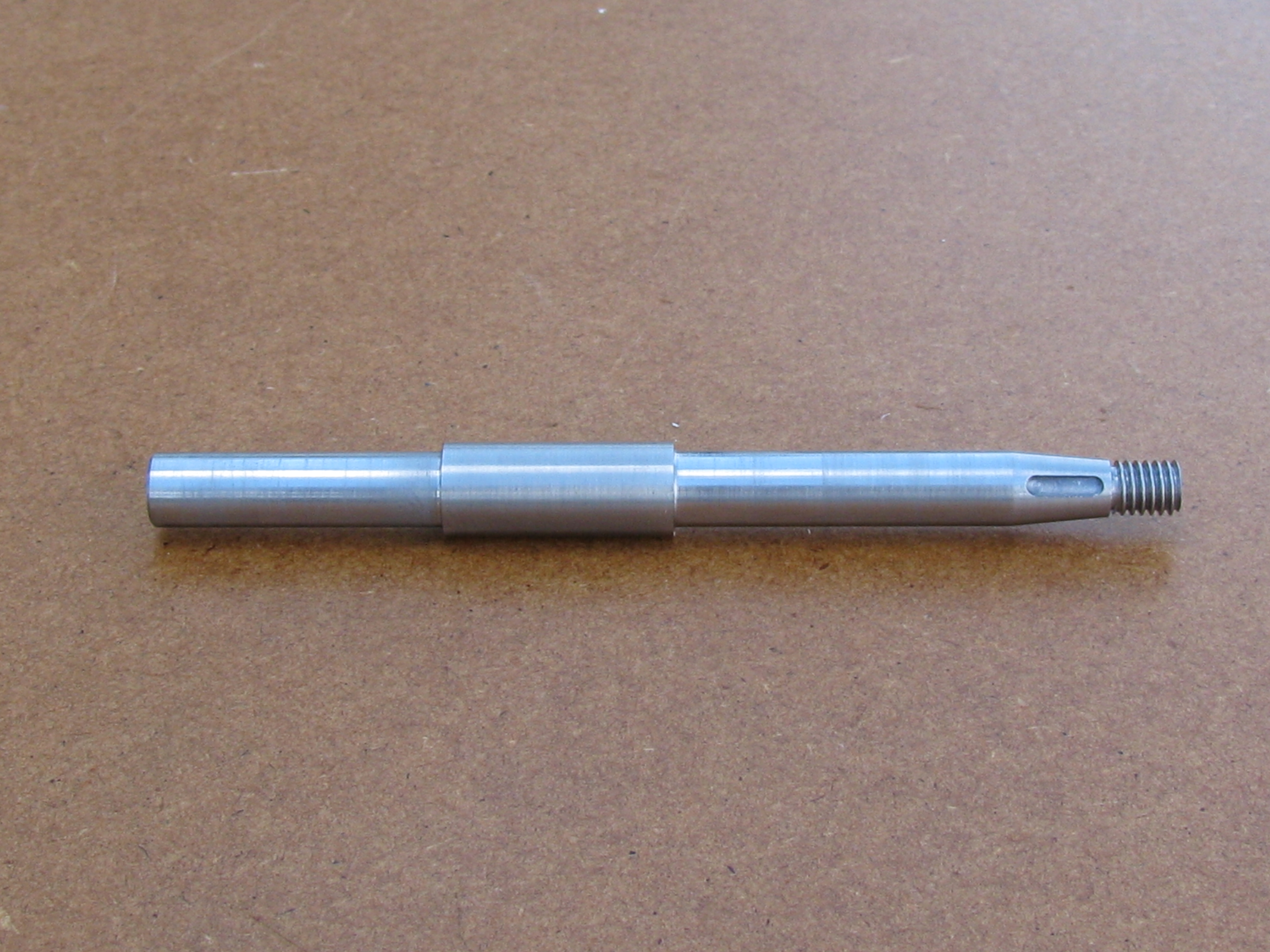
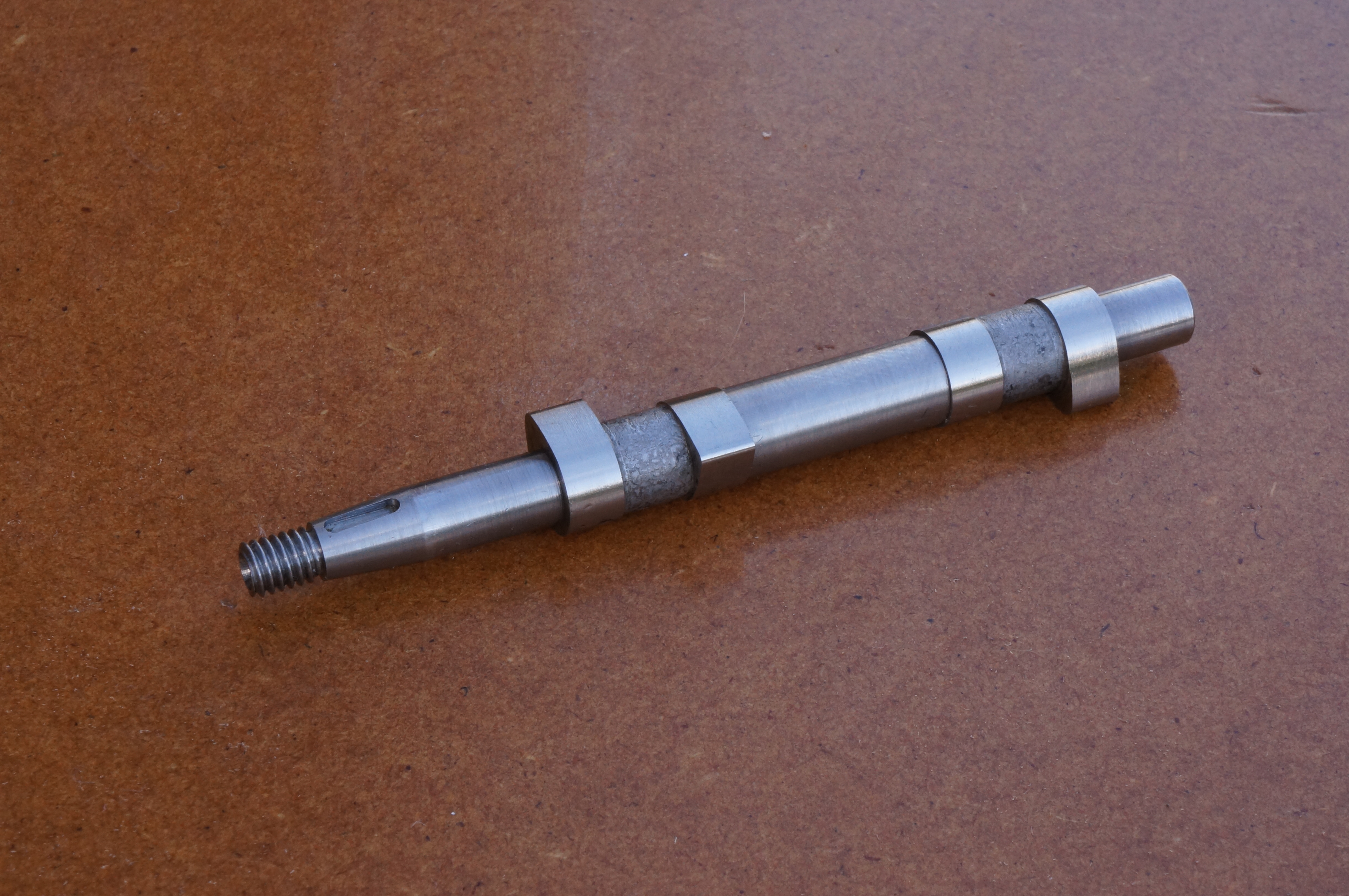
2011-08-20 – Finish turning the camshaft
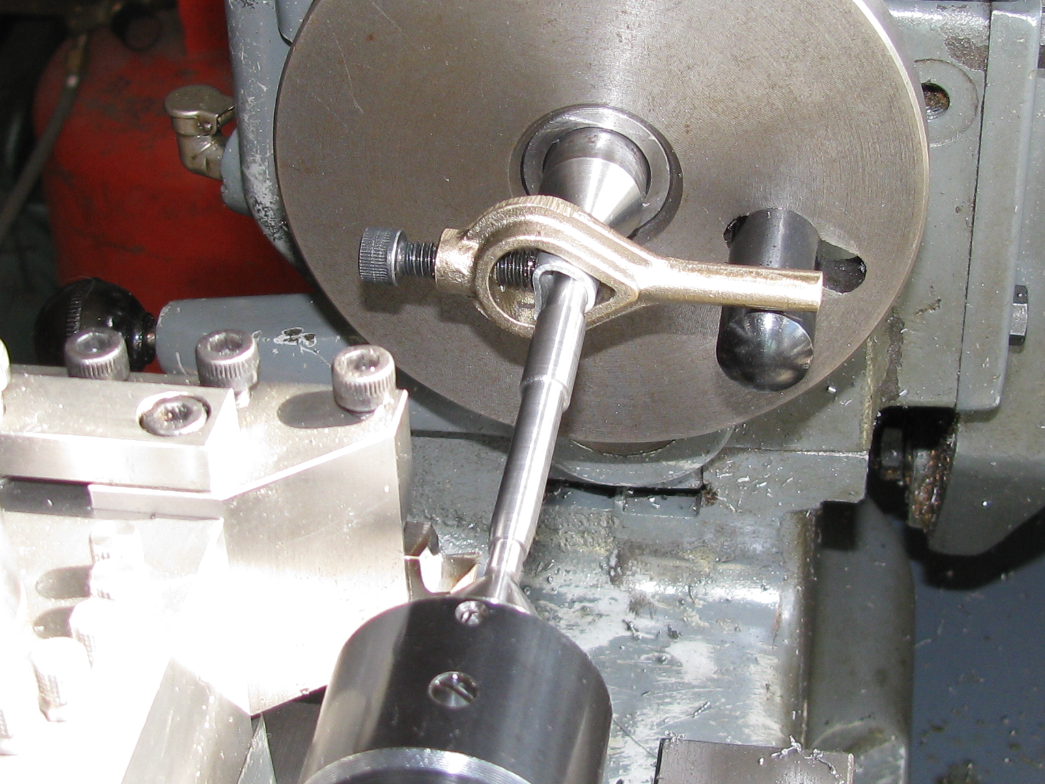
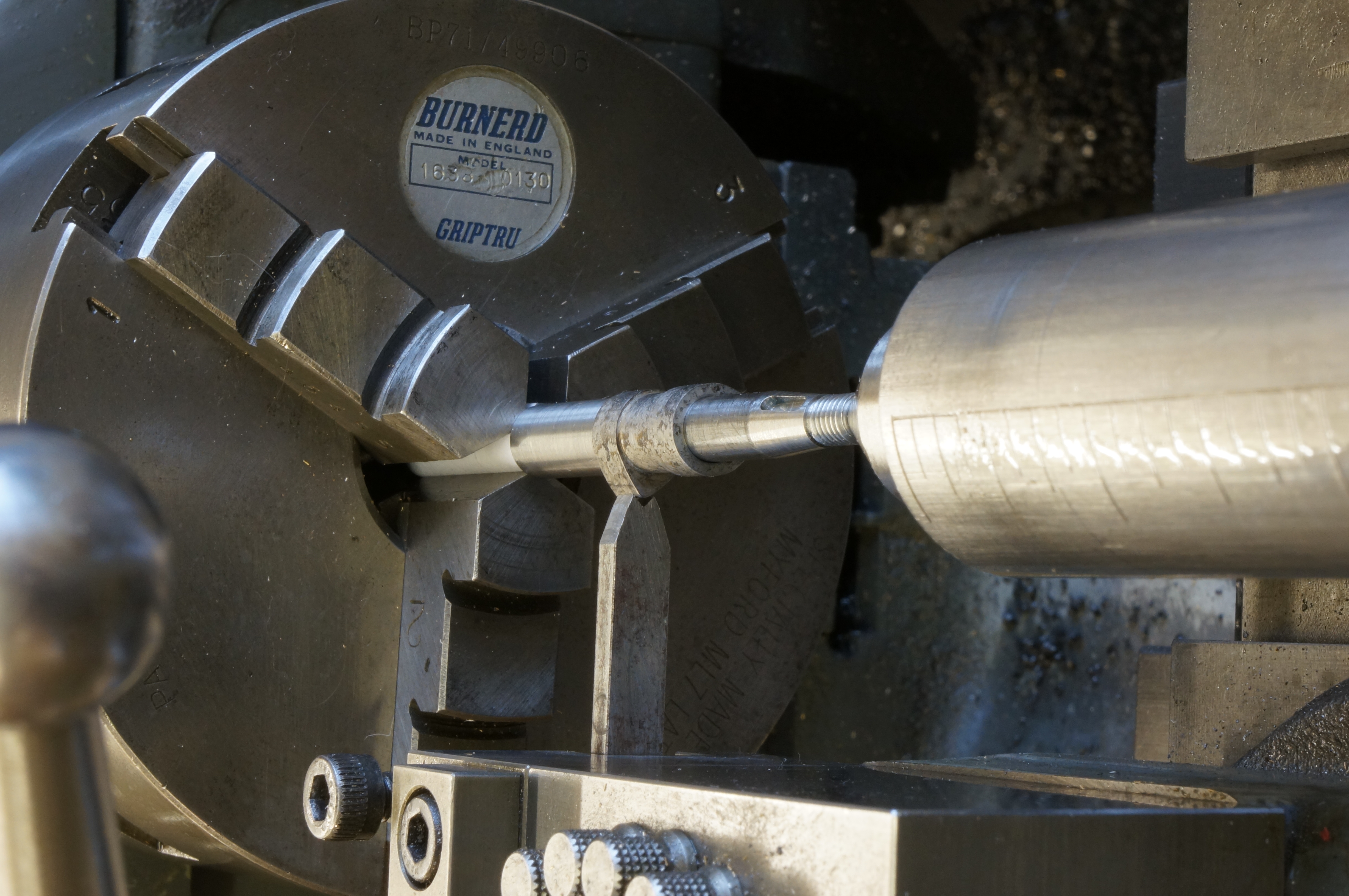
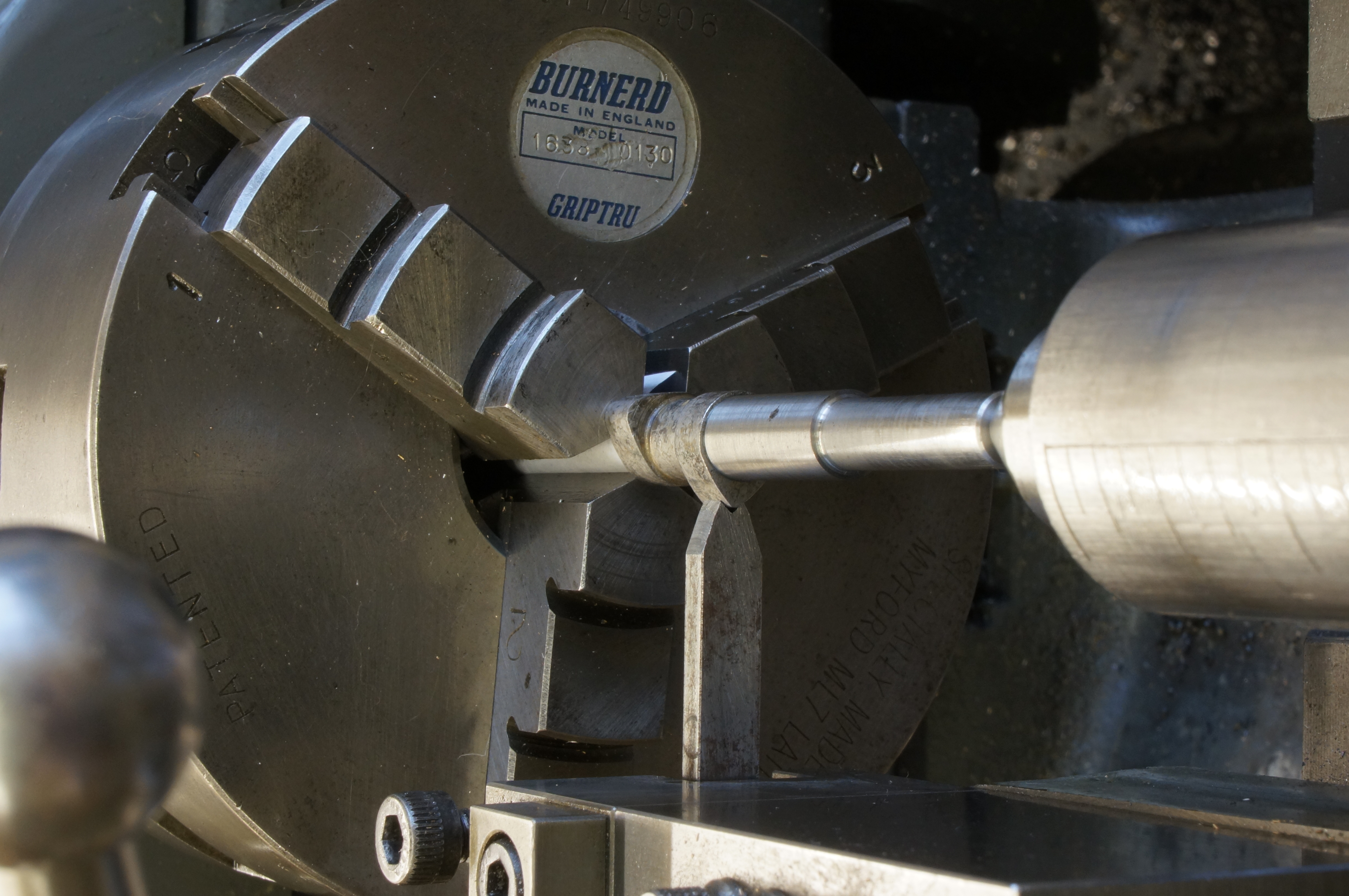
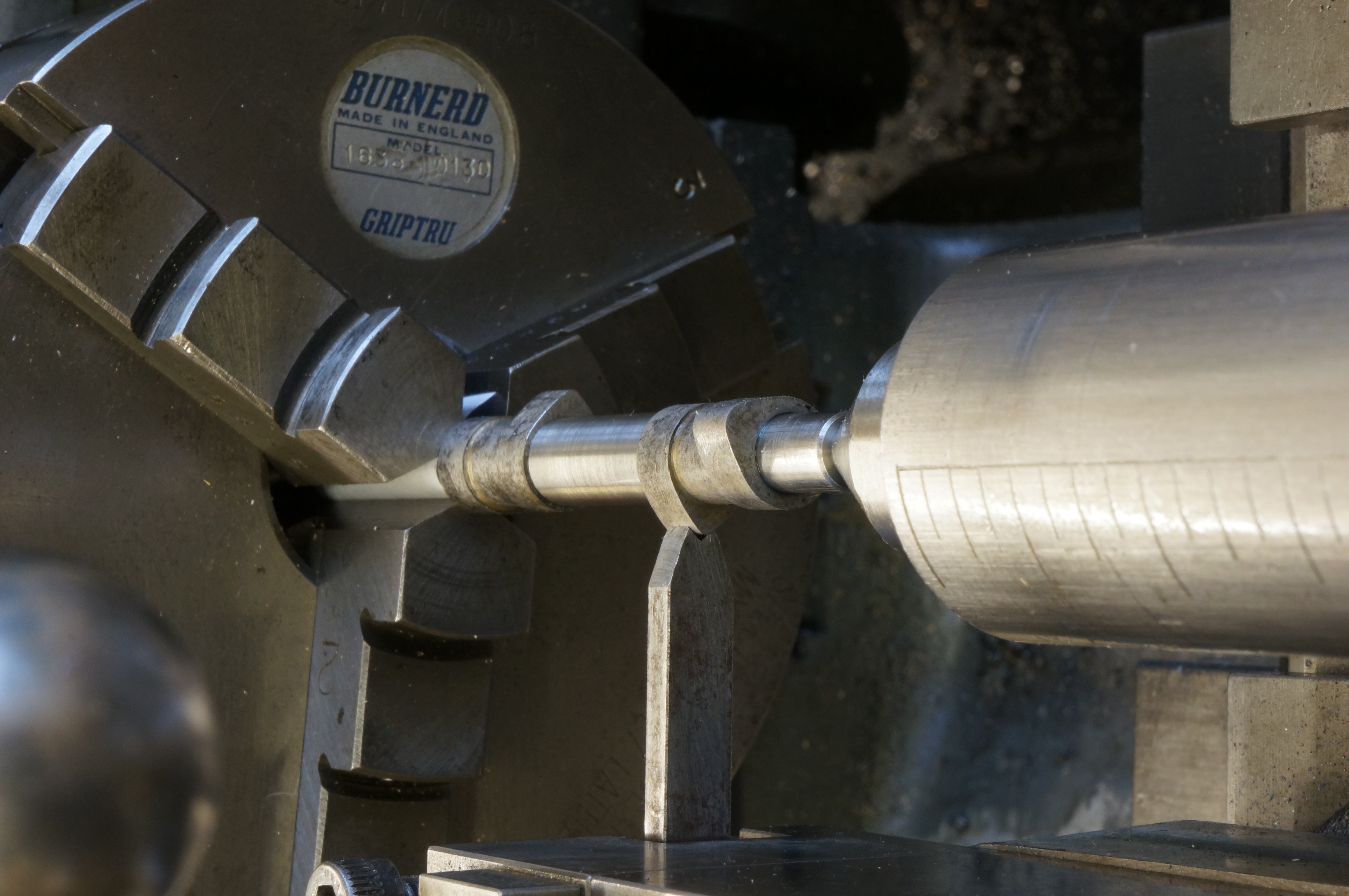
Having finalised the design of the magnet carrier for the ignition timing (it will be a ring bolted onto the timing gear) I now know the camshaft's length. I faced the already roughed out piece to the finished length, centre-drilled No.1 size, and set it up for turning between centres. With a freshly ground tool I took small cuts off the centre portion. At the last minute I remembered to check for taper and found it was slightly out. After adjusting the tailstock and turning the centre parallel, it was 0.0003″ below the nominal 5⁄16″, which does not matter. The surface is not as smooth as I would have liked, which suggests the bearing seats may need to be lapped.
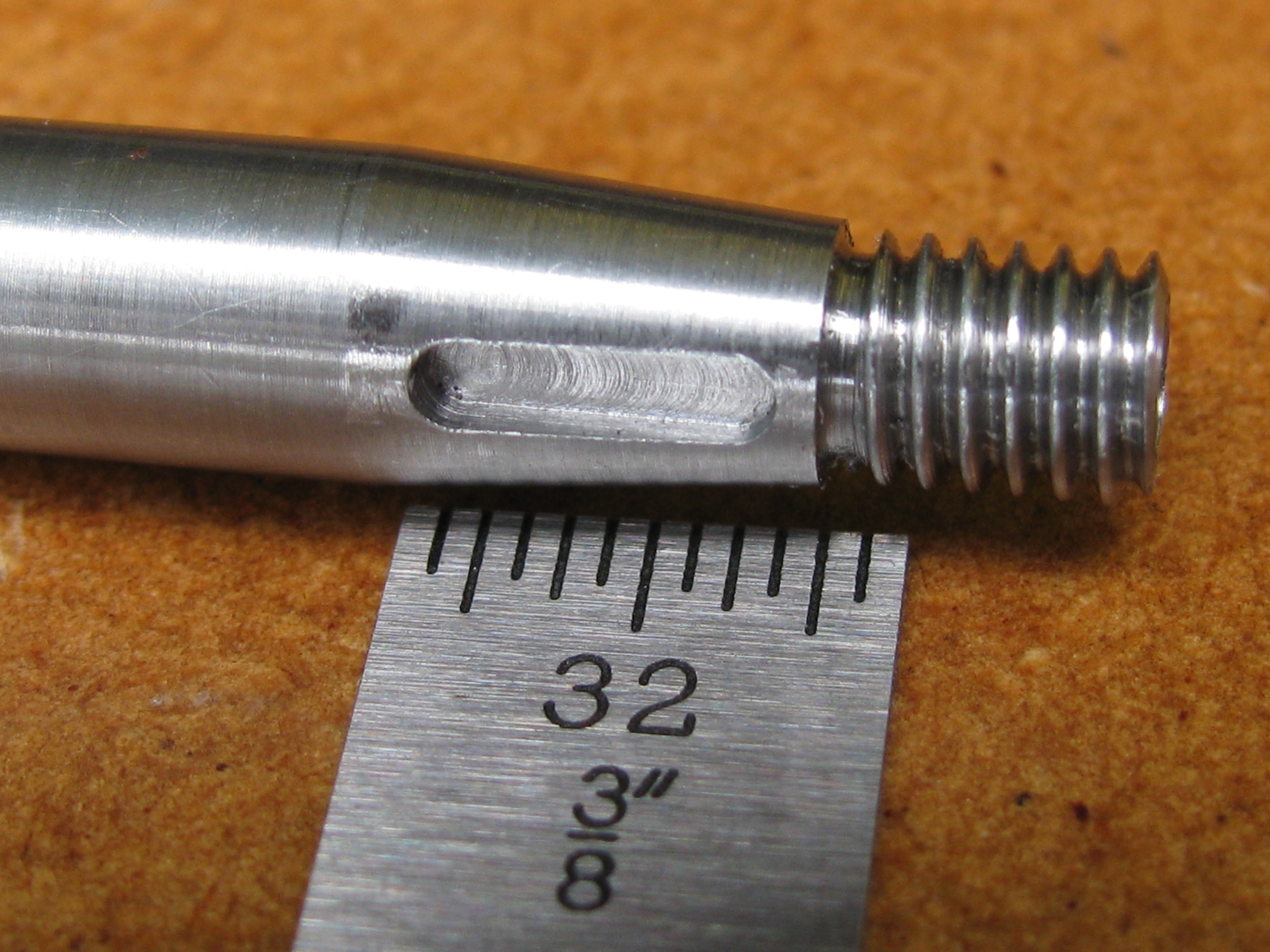
Working on the flywheel end, I got a taper of about 0.0001″ over the length. Running the tool back with reversed feed made it worse, with the cam seating 0.0003″ smaller than the bearing surface. This definitely means lapping. At the other end I left a slight step to get the diameters as close as possible without going too far. I left it 0.0002″ to 0.0002″ for lapping. Turning the shoulder, I ended up with the centre portion about three thou short. Ideally, the cams ought to be made a trace over length to compensate. I used a half centre to get at the end for turning the OD of the threaded portion and reverted to the live centre for grooving the thread runout. All of this work was done at 300 rpm. Last job was to set up for turning the taper. (4¼ hours)
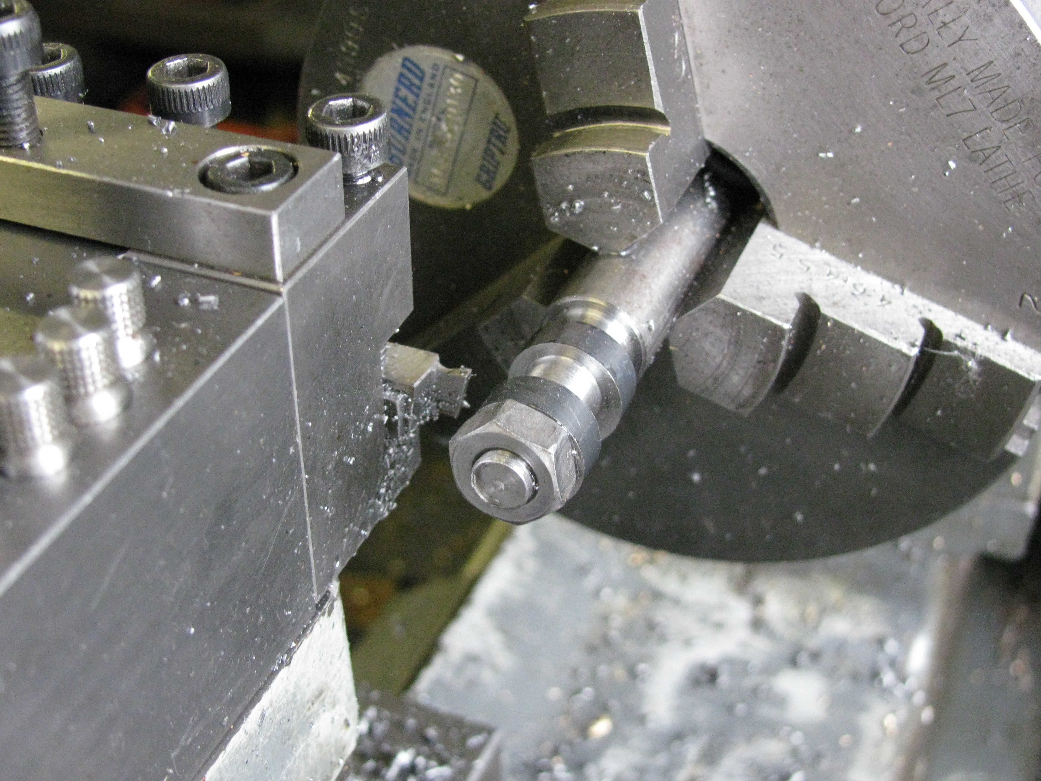
2011-08-27 – Taper turning, threading and milling
The taper turning attachment has been set at 5° for months, so that was easy. The taper was completed in 3 cuts. I don't understand my own notes, but it looks as though the finished size may have been arrived at a little sooner than expected. The taper setup was then changed for screwcutting.
| 2 BA | Cluster | 1st stud | 2nd stud | leadscrew |
|---|---|---|---|---|
| Driver | 30 | 38 | 35 | — |
| Driven | — | 40 | 46 | 85 |
The correct pitch for 2 BA is 0.81 mm or 0.0318898″ (to the nearest ten-millionth). Using Duncan Munro's ML7 gear program and my selection of change gears which includes some extras, I came up with a train that gives 0.0318893″, a theoretical error of 0.0000005″ which is probably good enough. With the topslide set at the half-angle of 23¾° cuts were taken to 0.019″ deep on the topslide dial, leaving 2 thou to come off radially. At this point I remounted the job in a collet and finished the thread with a well expanded 2BA die in the tailstock die holder, contracting the die until a stock 2 BA nut would just go on smoothly.
Next, I set up the vertical slide and made a copper lap for the camshaft.
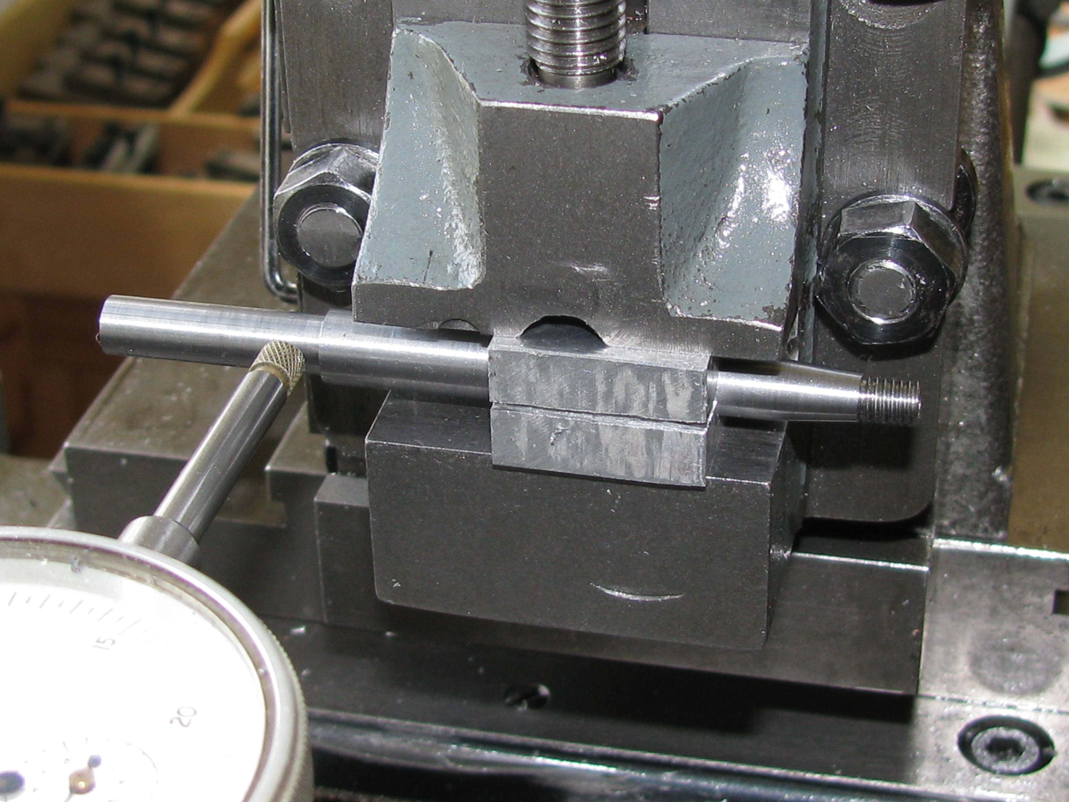
The original design calls for a woodruff key, but for that I would have to make a tiny cutter. I decided on a square section key, the same size as for the crankshaft pinion. For ease of manufacture, I have set the key parallel to the camshaft axis, rather than following the slope of the taper.
With the lathe set up for milling I made a clamping block for the camshaft. This is drilled and reamed, and then after slitting is used to hold the job without moving the vertical slide, so the job has to be on centre height. With the shaft lined up square I milled the keyway with a 1⁄16″ slot drill. (4 hours)
.
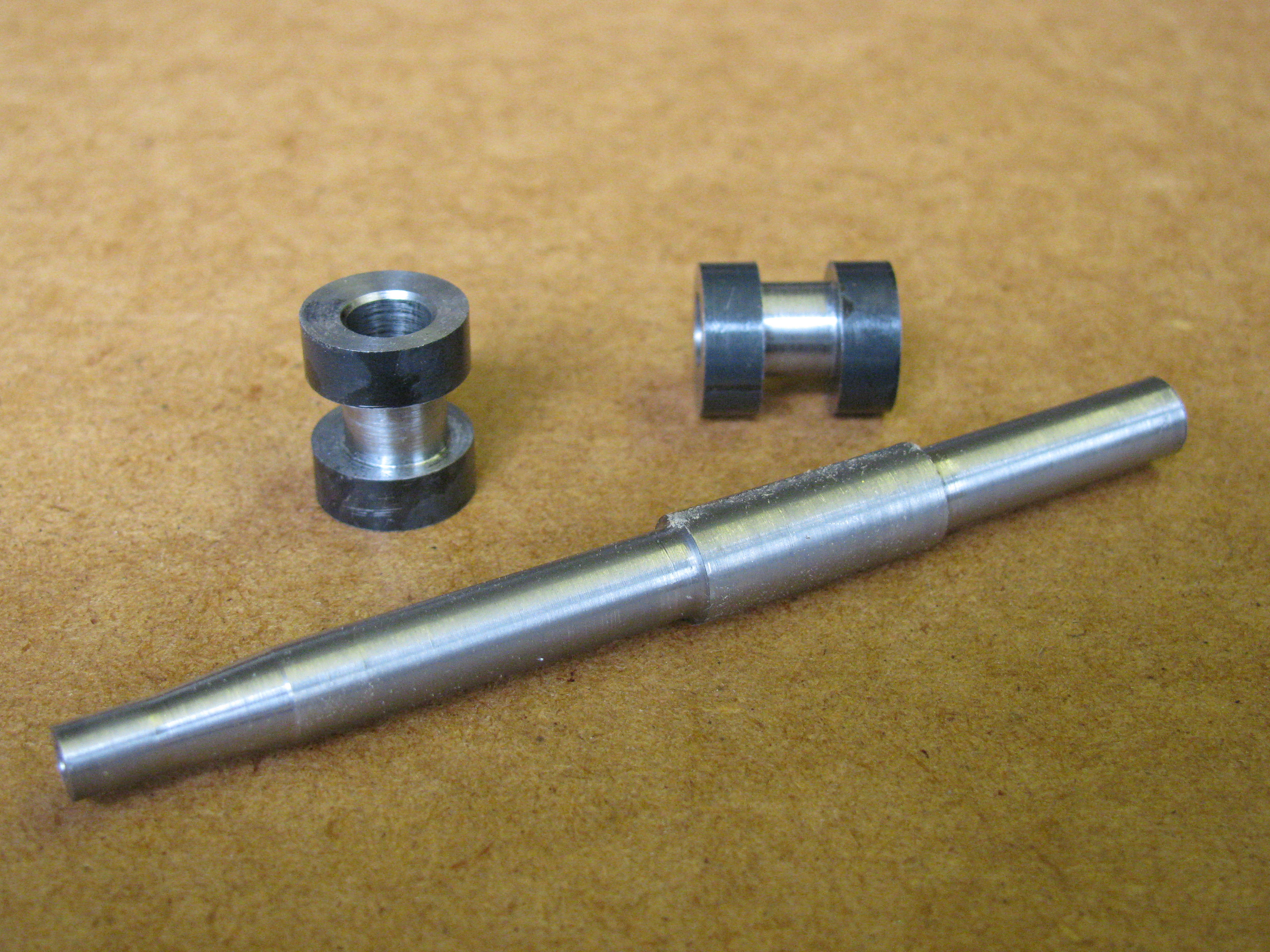
2011-08-28 – Lapping
I lapped the bearing and cam seating surfaces both ends of the camshaft to ¼″ dead on, or less than 0.0001″ oversize in parts, using the copper lap with 800 grit garnet paste. This was pretty slow in action, and seemed to take much more off the lap than off the job.
Lapping has not removed all marks from the turning tool, but the surface is generally very good and the bearings feel very smooth in operation. Finally, a chamfer was cut at the free end.
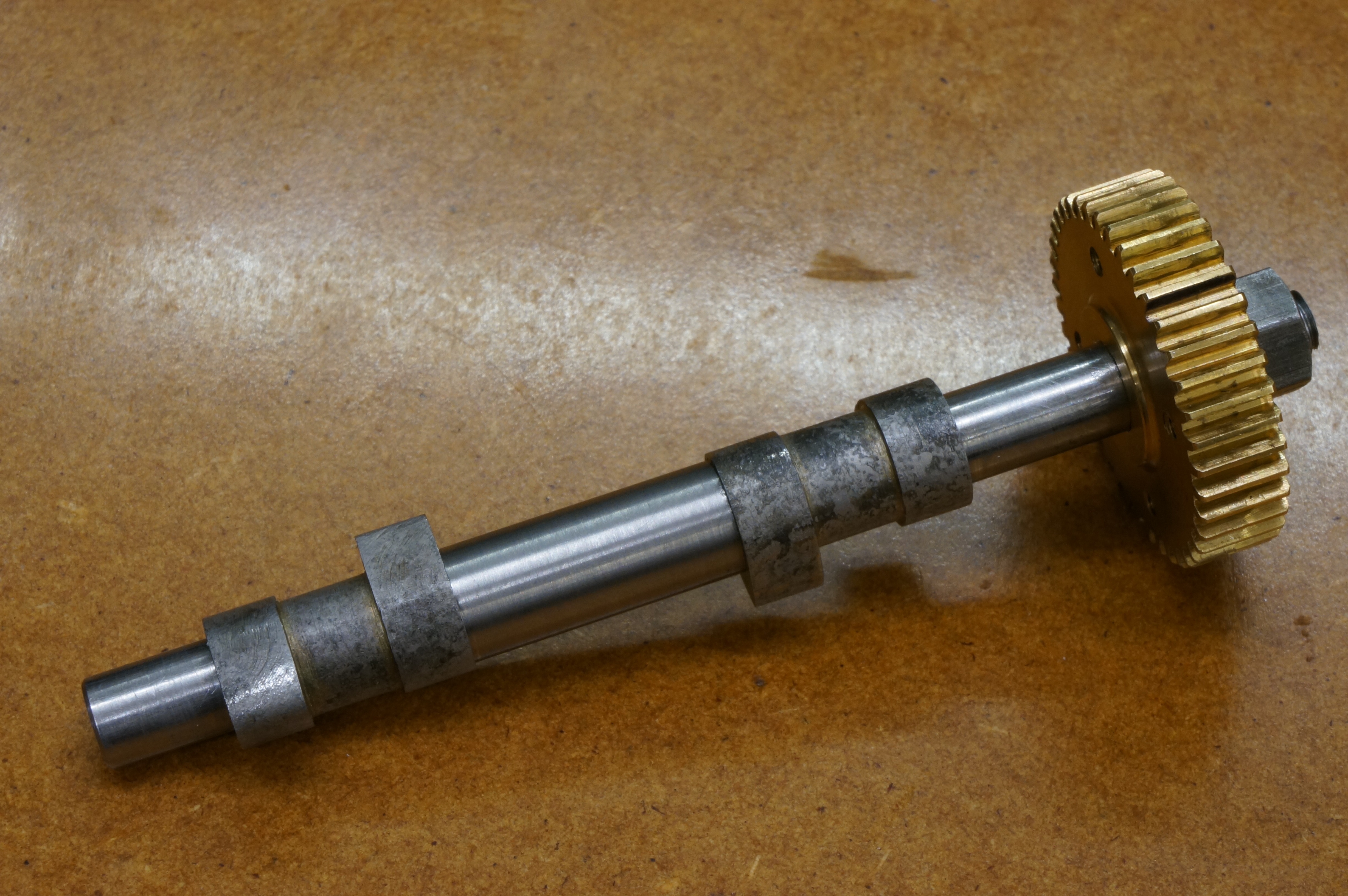
With the camshaft complete, work on the timing gears can resume, and I spent the remainder of the day sharpening a small boring bit for the taper in the camshaft gear. (2 hours)
.
2012-11-25 – More cam blanks
Yesterday I 'normalised' the remaining piece of ½″ silver steel from the kit, and a piece of 5⁄16″ from stock, for cam blanks and tappets respectively. The process is to heat to bright red and quickly bury in a bed of vermiculite to cool slowly.
Today I parted off three more cam blanks from the normalized piece and faced the ends. Parting was not easy, though in fairness the parting blade was not freshly ground. The finish I was getting when facing with a high-speed bit was not brilliant, so I tried a carbide tool, at 1200 rpm, but the results were no better. Forgetting that I wanted to compensate for the camshaft shoulders being a couple of thou short, and through miscalculating a cut, I managed to make one +0.001″ one to nominal length, and one to -0.004″. (2 hours)
2013-03-03 – Yet another cam blank
I have recently come to the conclusion that George Thomas' recommendation that silver steel should be normalised before machining may not actually make it easier to machine, not with my normalising, anyway. As the blanks made last time were a bit short, I decided to try some from silver steel stock as it comes. I parted a piece off and faced it to 0.627″ long. Using the 4-jaw chuck I was just able to get the dial gauge in position to set the blank with a 0.050&Prime TIR offset. I centre drilled and put through a 5.8mm drill, followed by a 6.0mm one, and then bored to 6.2mm, reamed ¼″ diameter at 200 rpm, and chamfered the hole for the radius at the camshaft shoulder. (2¼ hours)
2013-03-09 – Boring and grooving
Today I bored the three normalised cam blanks and then set them on a stub mandrel to turn the groove between the cams. These pieces did not machine anything like as well as with material in the as-supplied condition, which produces swarf in coils rather than crumbs. This was especially noticeable with reaming. (3½ hours)
2013-03-15 – A last blank and a milling mandrel
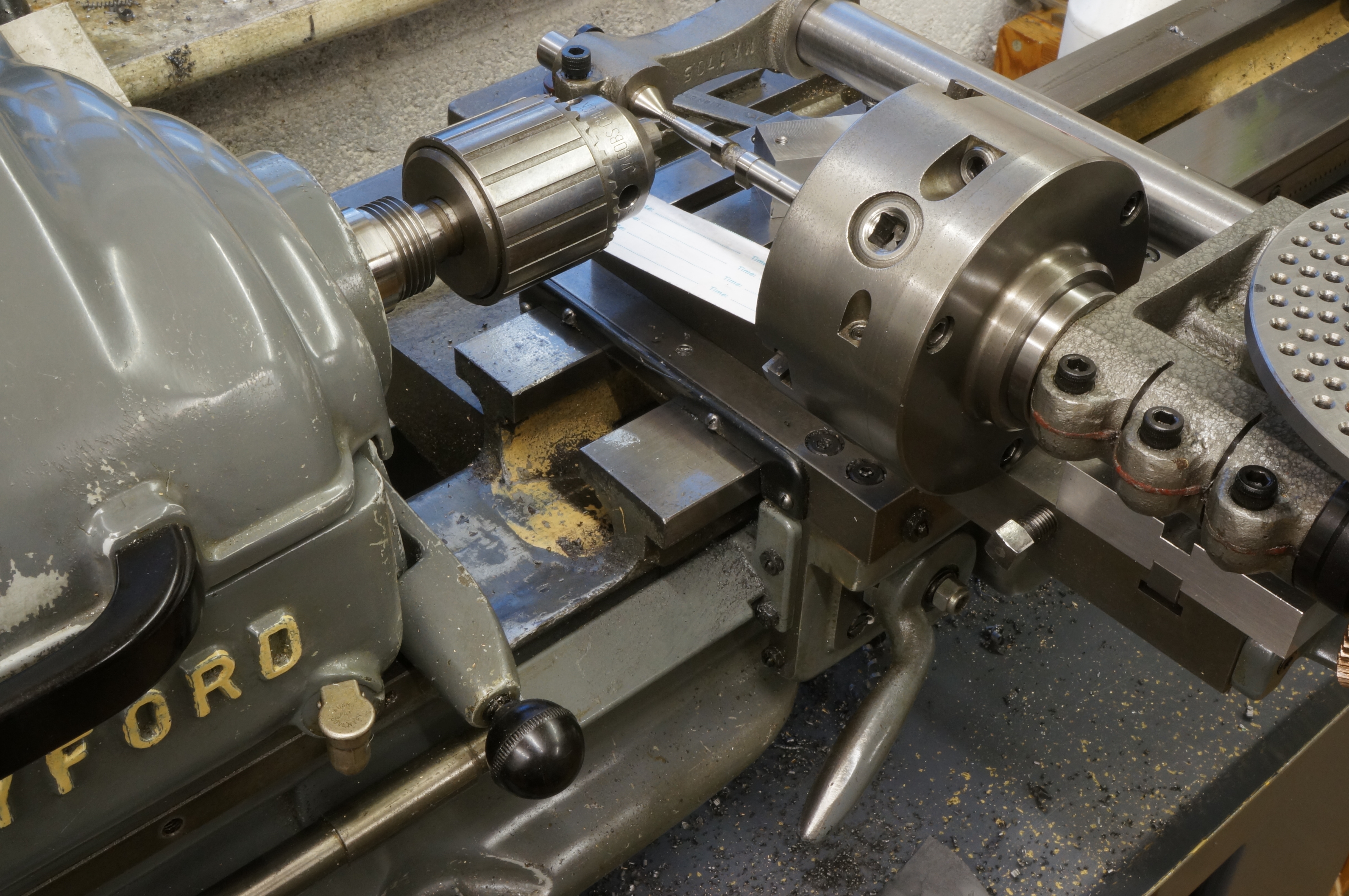
After a bit of indecisive messing about and tidying up, I made another cam blank out of non-normalised silver steel to provide a pair. As before: parted, faced both ends and to length, eccentric bored, and grooved on the mandrel which, of course, had to be set to run true in the Griptru chuck.
I started work on a longer stub mandrel for milling the cams, designed to provide clearance at each end for the cutter. I started by making a clamping nut with an integral sleeve, intended to ensure it clamps up square without distorting the rather slender mandrel.
Finally, I turned all the diameters on the mandrel.
2013-03-16 – Mandrel & DTI mounting block
The first job today was to cut the 1/4″ x 32 TPI thread on the mandrel. This was screwcut and finish chased to ensure accuracy.
Next, I started work on a block to enable a DTI to be clamped directly to the lathe bed, rather than using the magnetic base which use last time and managed to move part way through the job. I sawed out a lump of steel and machined all 6 faces, using the 4-jaw chuck, and drilled and tapped a hole in one end for the DTI clamping bolt. I then cut out a clamping plate, drilled a hole in the middle and mounted it by the hole on a stub mandrel to turn it over the ends to fit between the lathe bed sheers. Lastly I drilled the hole through the block for the clamping bolt.
It is difficult to set a job to run true in the Myford dividing head with the worm in place, so I took it off and set the stub mandrel running as close to true as I could get it. (4½ hours)
2013-03-17 – Setting up and trial milling
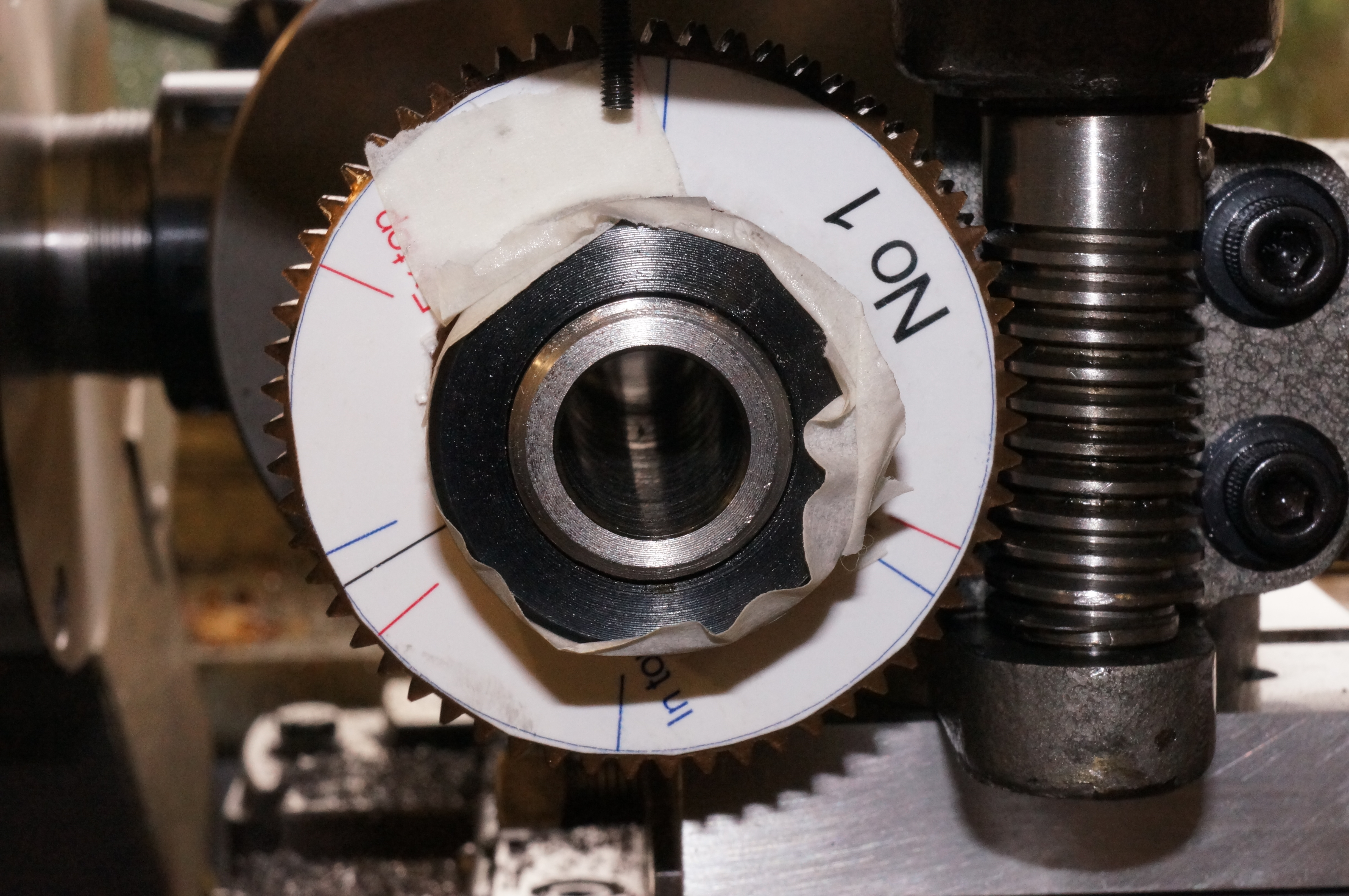
After reassembling and adjusting the dividing head and changing to the No 2 division plate I mounted one of the normalised cam blanks for milling. I started on the exhaust cam. Coming round the nose, I was surprised to find that in a couple of positions the cutter was not touching. Near the end I lost count of my position and I had forgotten to mark the starting position anywhere. The base circle measures 0.361″, against a nominal of 0.343″ diameter, meaning there would be 9 thou to be ground off rather than the intended 0.005″. Also, the nose of the cam was in the wrong place in relation to the blank.
After this I drew up a pair of protractors, showing the salient angular relationships for each cam pair, in the hope that this would help to avoid losing count completely. I printed them off, cut them out and fitted one to the face of the worm wheel. I put a small bolt through a hole in the index plate to act as a pointer.
With another cam blank in place I cut an exhaust cam successfully, but while milling the first flank of the inlet cam I advanced the cut without making the corresponding rotation, resulting in an undersize cam, but I carried on to completion for the practice. (3¼ hours)
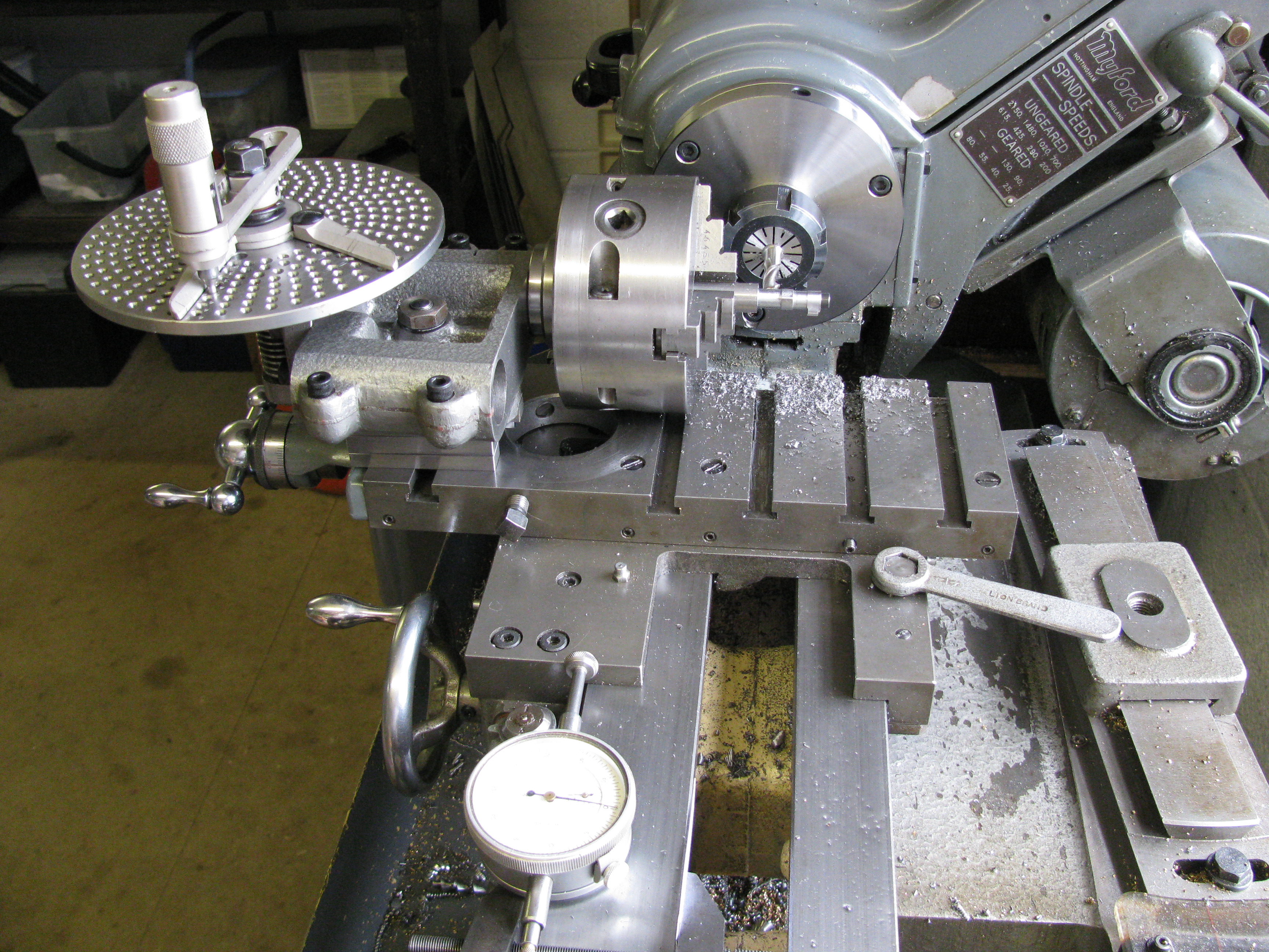
2013-03-18 – Cam milling
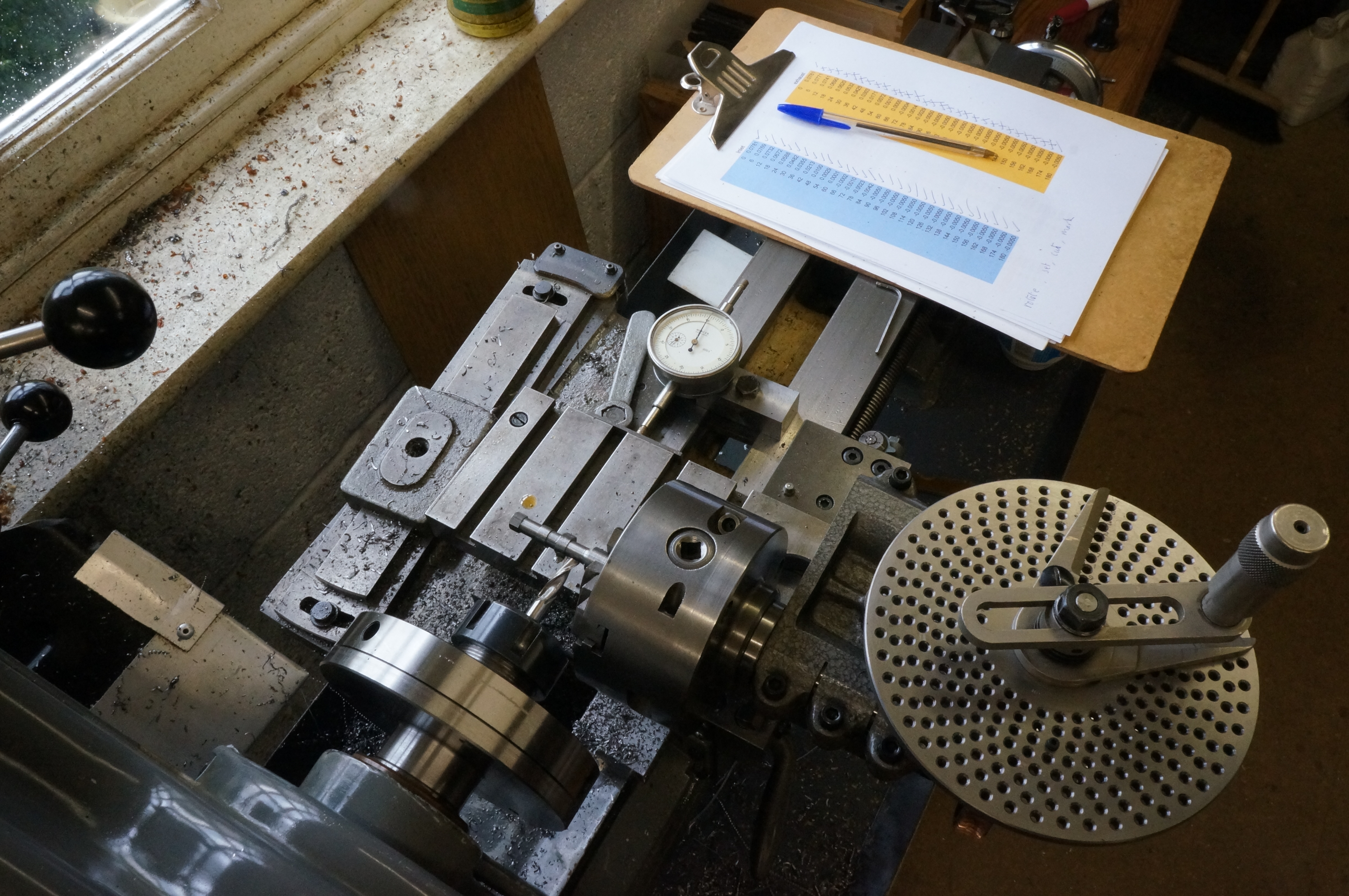
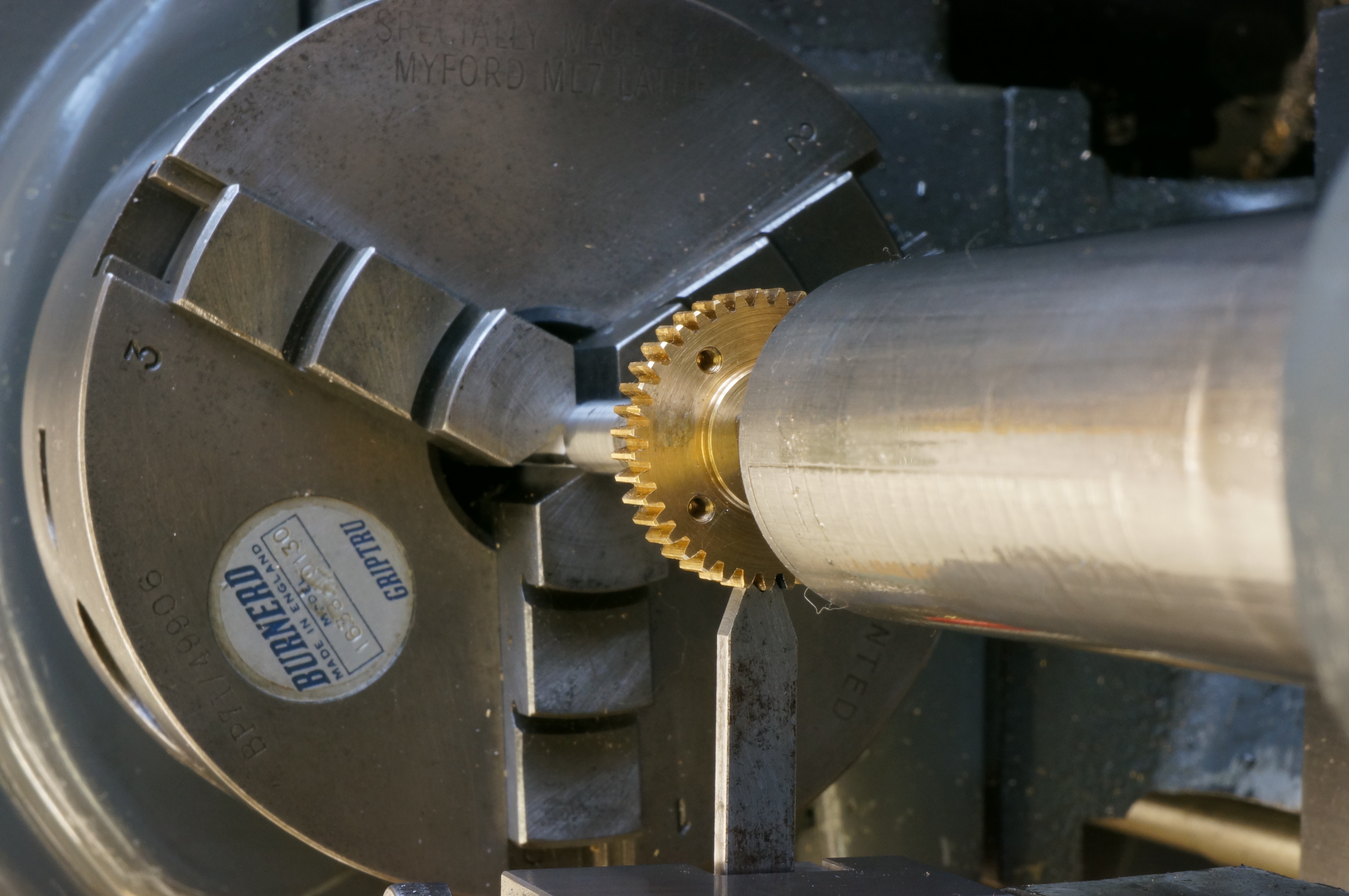
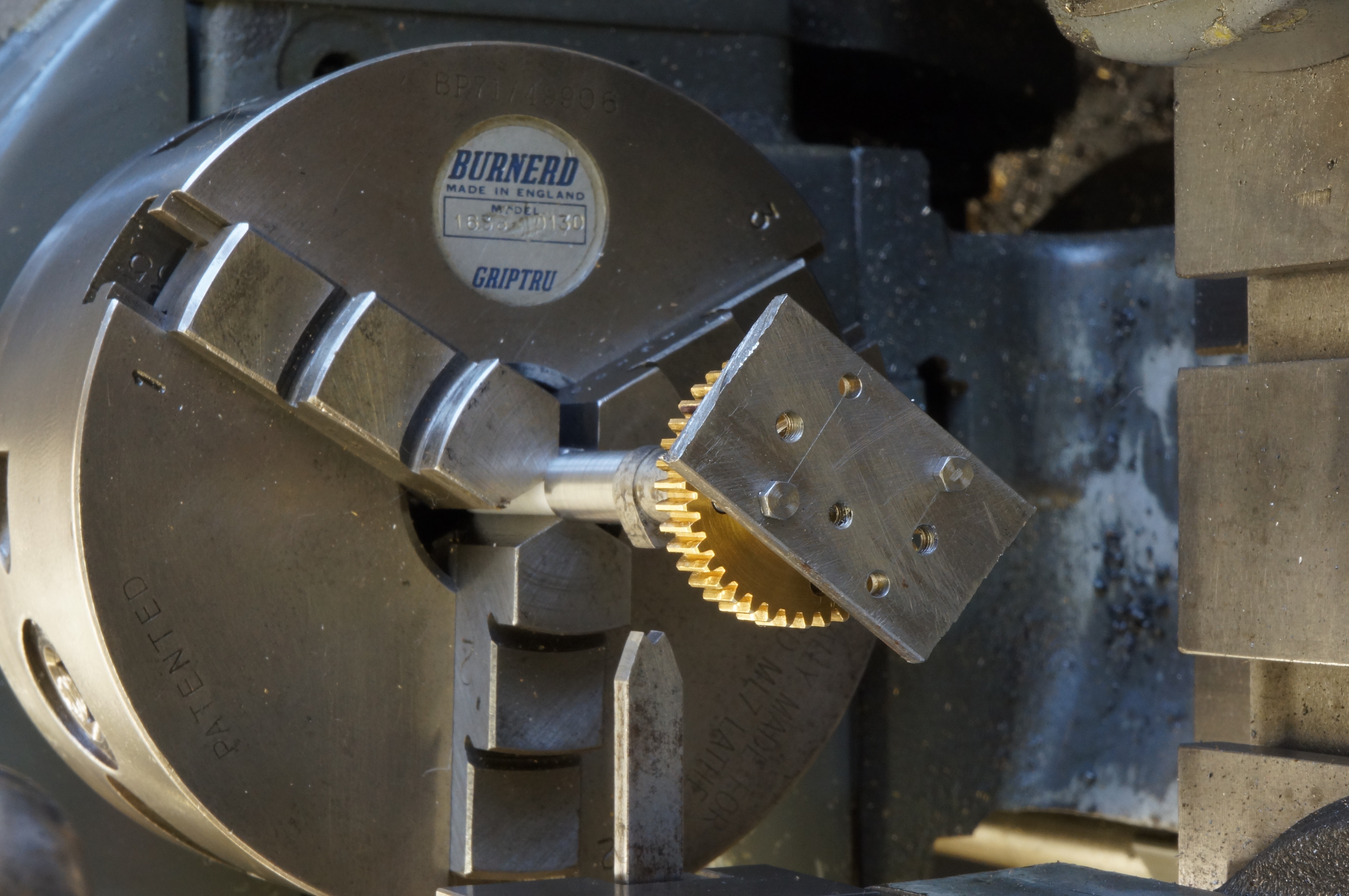
Today, at the third attempt, I managed to produce a cam blank with a pair of good cams, and then went on to make another. I used the blanks that had been left in the as-supplied state, but the finish was still very craggy. The photo shows the general set-up, using the bed-mounted dial gauge to estimate the offsets to 0.0001″, and including the all-important table of offsets, blue for inlet, yellow for exhaust, with each one being ticked off in turn. As the cams are only being rough machined, for later grinding (somehow), I used a relatively coarse increment of 6°, this being one whole turn on the dividing head.

.
2015-10-30 – Starting a camshaft grinder
I have collected enough materials to make a start on the camshaft grinder.
2016-06-04 – 12 Milling the cam templates
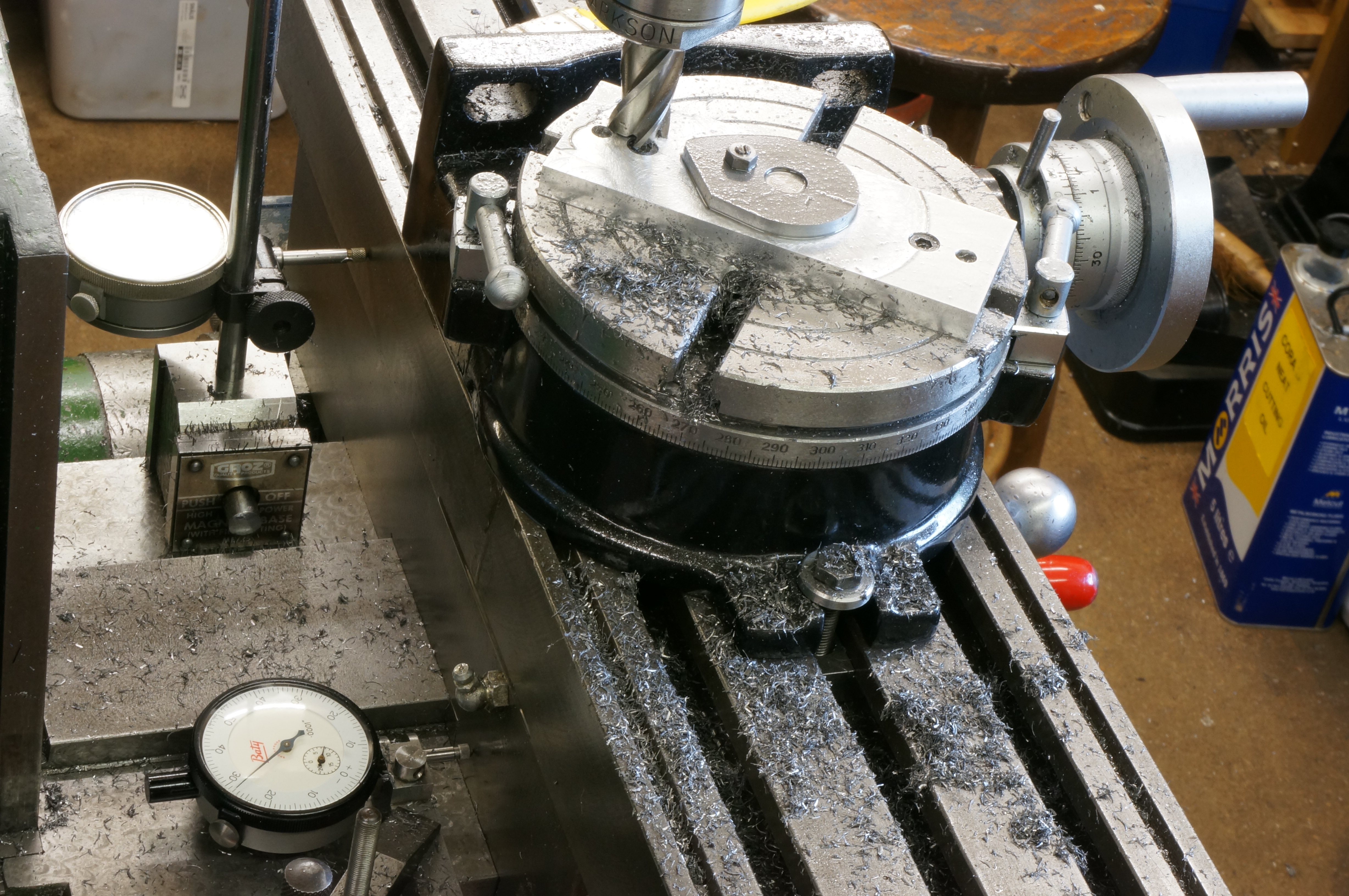
Here is a photo showing a cam template being milled. This is tooling so I am not going into detail, just filling in the long gap in this diary.
At this point the far flank is done and I am working round the nose radius. The dial reading for the milling machine y-axis was unreliable at the time (I later discovered it had possibly never been right from new). Two dial gauges are in use; a long-stroke 0.001″ one for the general position, and a 0.0001″ one for accurate degree-at-a-time milling of the cam profile, reset as necessary using slip gauges. The templates are scaled-up cams, 5 times size.
2016-11-12 – Completing the Grinder
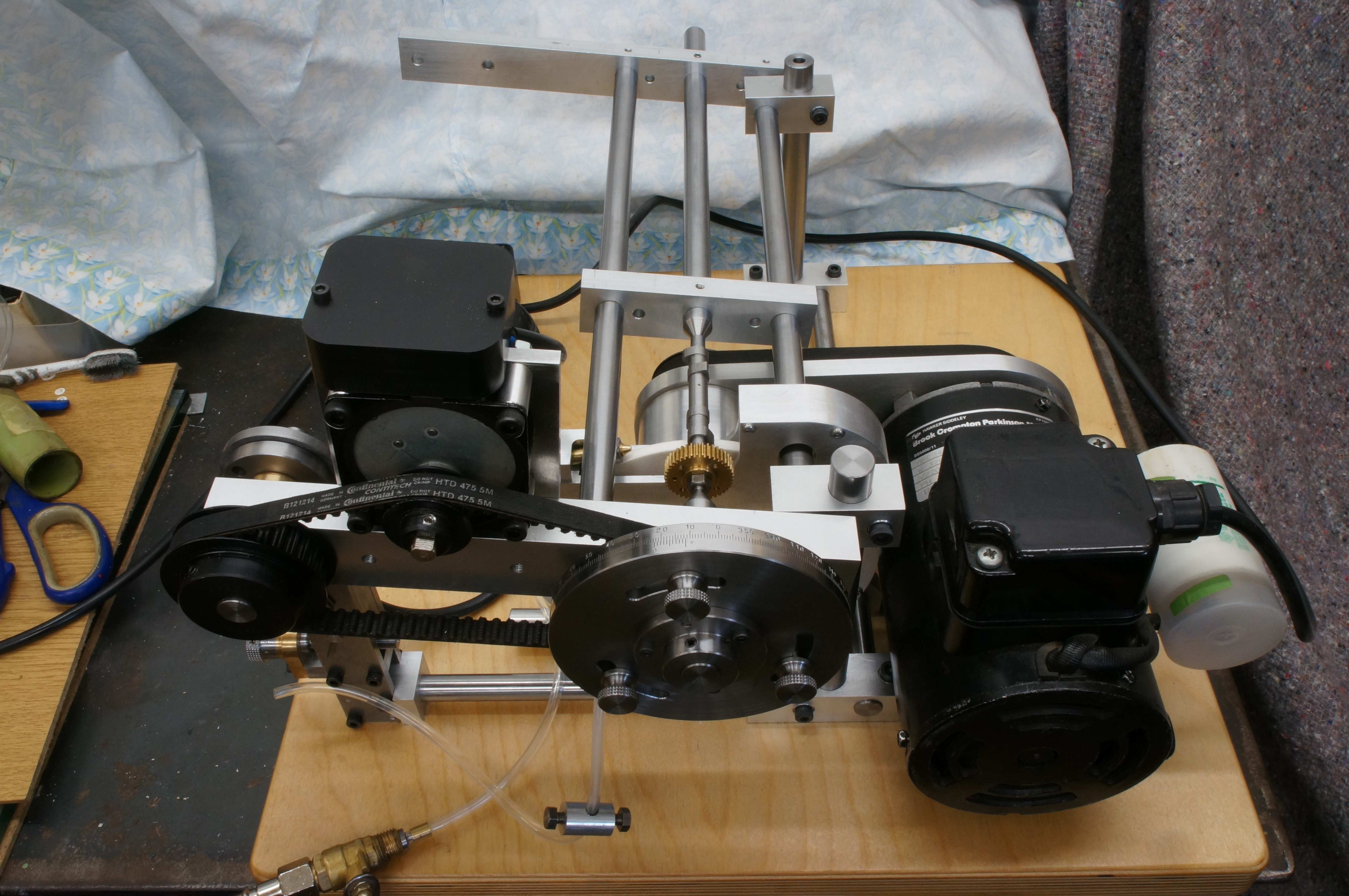
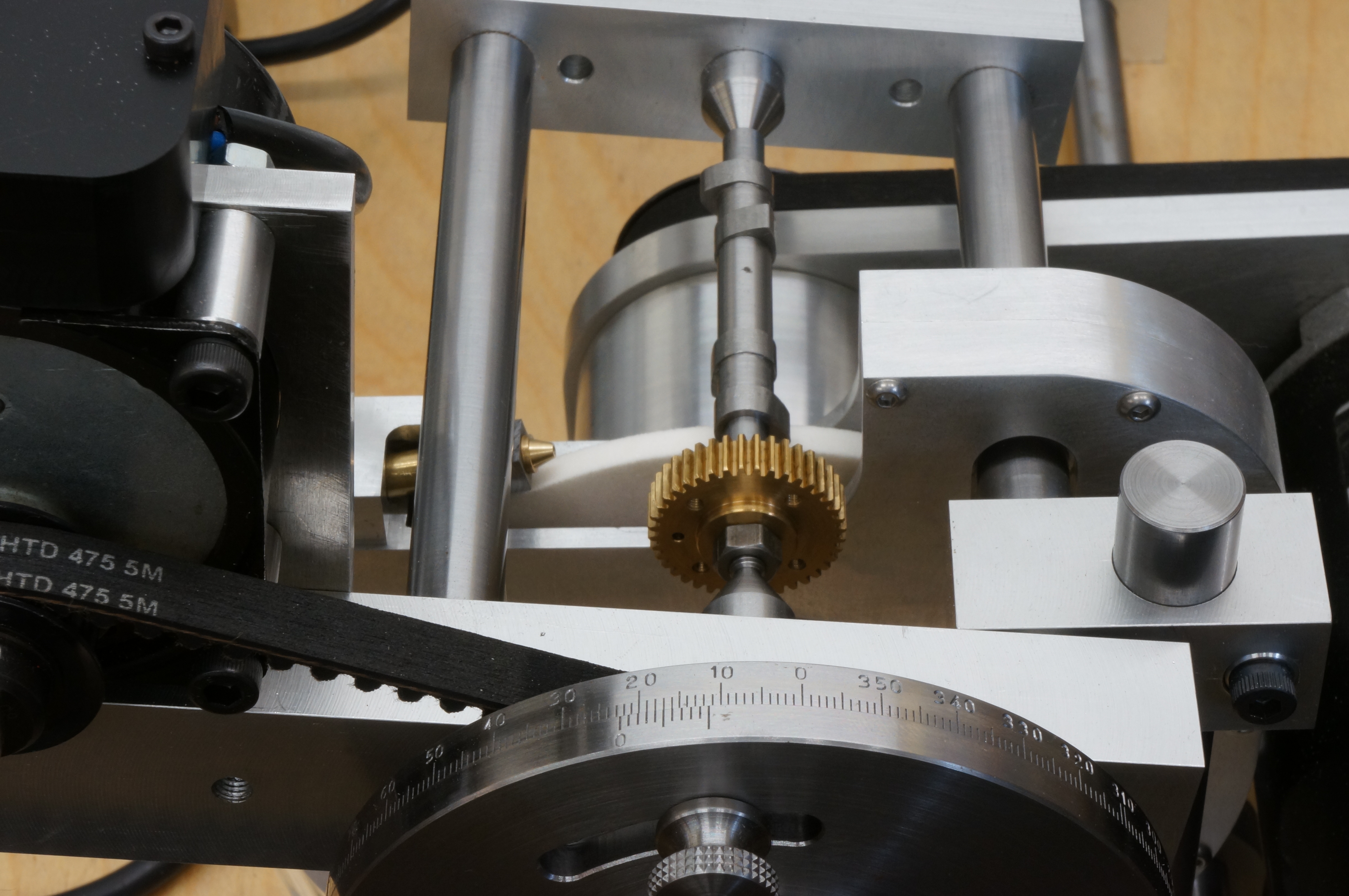
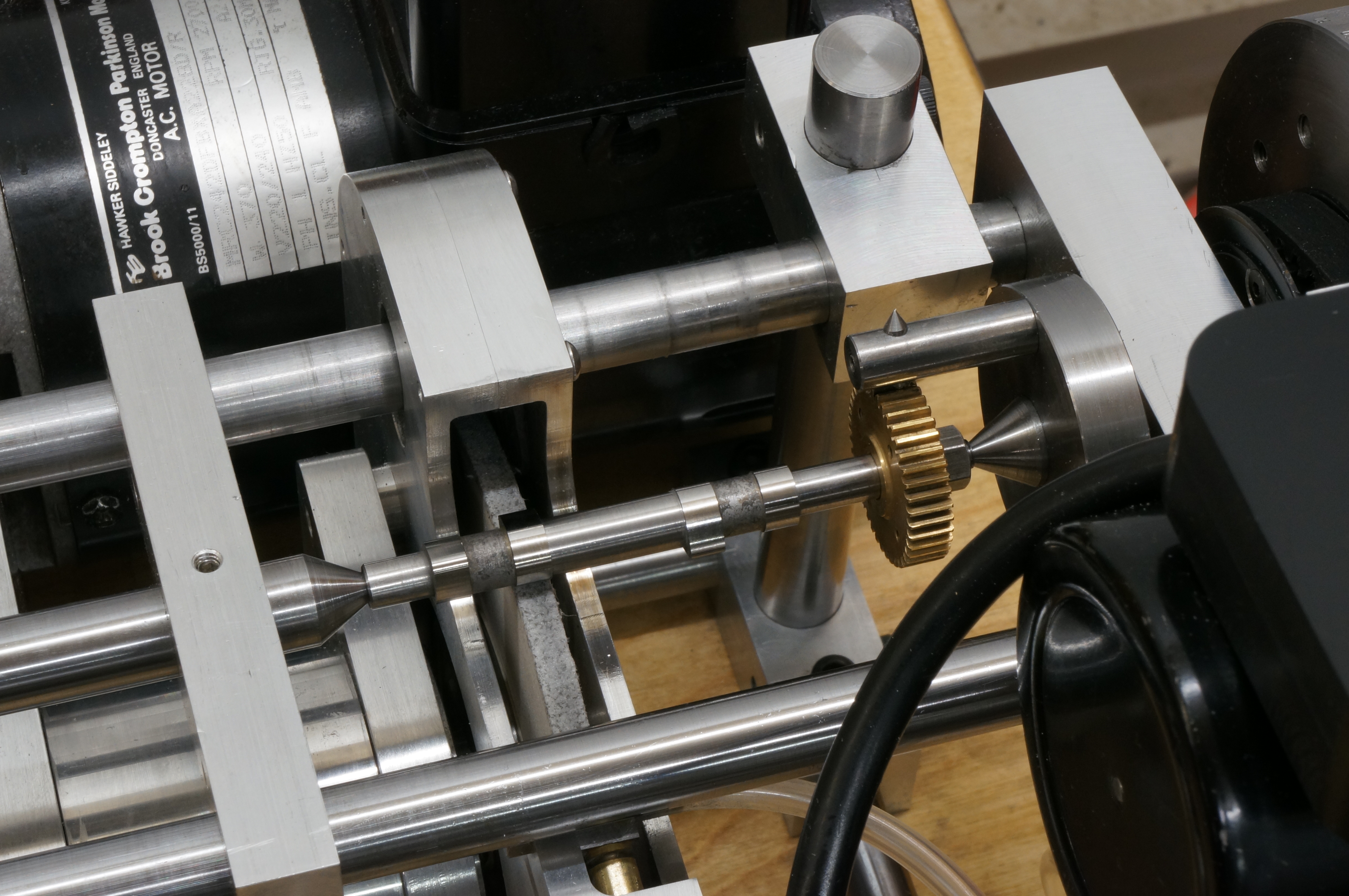
Here are a couple of photos of the grinder, almost complete. The camshaft is shown in place, but as yet the cams are not hardened and not fitted. I still need a form of catchplate to drive the camshaft, and a setting gauge to enable the cam template and camshaft to be phased correctly.
2016-12-10 – Fitting the key and trial assembly
With the drive plate and setting gauge completed, I was able to set the grinder phasing ready for the camshaft assembly.
In the afternoon I carried out the first work on the engine itself in over a year. This was the fiddly job of hand fitting the 1⁄16″ square key to fit the camshaft and gear.
After this I hardened the cams (managing to drop the red-hot cams on the floor at one point). I expected the cams to shrink a little on hardening, but in fact, after cleaning them up, they were slightly looser on the shaft. With the camshaft loosely assembled I tried to put it in place to check for length between the bearings, but it won't go in until the cams are ground. If it proves to be a bit tight, the bearing faces can be skimmed to suit. (4¼ hours)
2017-01-01 – Camshaft assembly gauge
I cut piece of 1⁄8″ × 1⁄4″ mild steel, milled the ends square then used a form milling cutter to put a 90° notch in one end. (1 hour)
2017-01-07 – Assembling the Camshaft and Grinding Trial
First, the assembly gauge needed filing down until just narrow enough to locate on one tooth of the timing gear.
I knew the assembly process would involve a sequence that needed to be rigidly adhered to if the camshaft was to come out right, so to make it completely foolproof I followed a written procedure.
- Put No 2 cam set away somewhere safe so the sets cannot be muddled up.
- Mark the timing tooth (in line with the keyway) on the timing gear.
- Mount the dividing head on the back of the lathe spindle.
- Set the dividing head for a span of 35 holes on the 42 hole ring (7 holes per degree).
- Set the timing gauge fork at centre height in the toolpost.
- Clean the camshaft parts and assemble the shaft, No 1 cam pair loosely in place, and the gear wheel with key and nut.
- Put the shaft in the 3-jaw, not tight, and bring up the tailstock for support.
- Wind in the cross-slide so the gauge sets the top dead centre 'timing tooth' of the gear.
- Tighten the chuck and withdraw the gauge.
- Rotate the dividing head backwards 20 turns plus 35 holes, (125°).
- Back off the tailstock, and remove the timing gear with the puller (a plate & two screws).
- Reposition the tailstock ready.
- Apply high strength Loctite to the shaft.
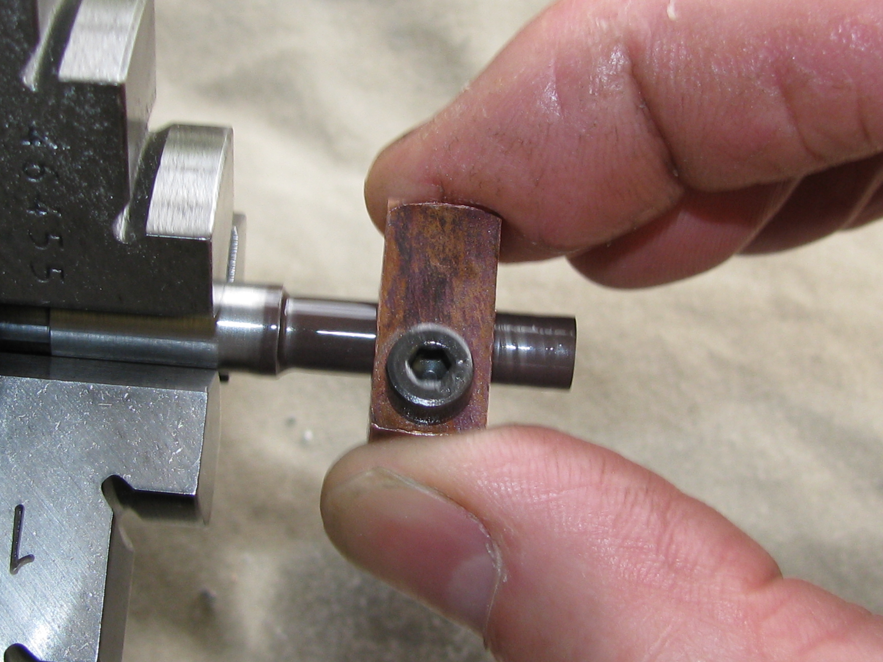
- Slide the No1 cam set, pointy (inlet) cam first, home against the shoulder and locate with the gauge fork bearing on the inner (inlet) cam tip.
- Support with tailstock and leave to cure.
- Turn the shaft end-for-end and locate lightly in the chuck.
- Support the outboard end with the tailstock.
- Rotate the camshaft in the chuck to set the No1 inlet cam to the gauge.
- Tighten the chuck and withdraw the gauge.
- Turn the dividing head 30 turns, (180 °);
- Slacken the tailstock.
- Search for No 2 cam set.
- Apply high strength Loctite to the shaft.
- Slide the No 2 cam set, pointy (inlet) cam first, home against the shoulder and locate with the gauge fork bearing on the inner (inlet) cam tip.
- Support with tailstock and leave to cure.
- Job's a good 'un.
Now, of course, nothing is completely foolproof. The procedure did not tell me to check that the chuck was screwed firmly on to the spindle nose. The job is not so good, it seems. I think it moved in positioning for the first pair, and that the first and second pairs are at the correct 180° apart. I am not sure what effect this might have, but the proof, and perhaps remedy, will be in the grinding.
A trial grinding cut suggests there is an error of about 4°. Checking the CAD drawings, the maximum error that the five thou grinding allowance will permit is 2°. More cursing. I will have to grind the cams to what they want and then re-time somehow, perhaps by cutting another keyway.
Continuing with No 1 inlet cam, I found I needed a 5° offset to get an equal cut on both flanks of the cam. I set the coolant spray up, which causes a lot of mess, and continued grinding the cam until it cleaned up all round. The diameter over the heel came to 0.342″ leaving a further 0.0016′ depth for finishing. (4¾ hours)
2017-01-14 – Rough grinding another cam
For accurate setting up of the grinder geometry, the axis of rear pivot bar needs to be set to the same height as the top of the wheel. Today I completed a height setting gauge and duly set the grinder.
With that done, I ground the No 2 inlet cam to clean up all round. Much of the rear parts of the grinder are stuffed with kitchen roll to absorb the coolant spray.
A feature of the cam grinder design was that it could include a low speed oscillation of the cam across the wheel face, driven by a worm gear from the cam drive. I never got as far as building this arrangement and instead am providing the same motion by pushing gently sideways on the rocking frame as it moves up and down. At one point I moved it over too far and grazed the side of the adjacent exhaust cam. It's not bad, just one of those irritating imperfections.
When I switched the wheelhead off, the wheel's inertia made the (left handed) nut come loose. After re-clamping it will need dressing again before use. (4¼ hours)
2017-01-17 – Rough grinding the exhaust cams
With the grinding wheel tightened up, I dressed it again and adjusted the the pivot bar. I turned the protractor to the correct position, fitted the exhaust cam template. and double checked the angle setting. I solved a slight foul by taking a scew out of side of the wheel guard to allow enought clearance for the drive pin.
I ground No 1 exhaust cam to to just clean up all round, to 0.3447′ at the smallest dimension and 0.4248′ over the nose. the target final sizes are 0.3388′ over the heel and 0.4194 over the nose, so there is a further 0.0027′ radially, to come off the nose and 0.0029′ at the sides. (2¼ hours)
2017-01-22 – Cutting a new keyway
Now I am satisfied that a 5° angular shift will accommodate the error in the cam timing, I can cut a new keyway at 185° from the original. Getting this right involved another tricky sequence with the dividing head mounted on the cross-slide.
First thing was to make sure the shaft is level and accurately position the existing keyway on centre height. The keyway corresponds with a tooth on the timing gear, but it is easier to set accurately with a pointer in a gap, so the dividing head is backed 4½° for half a tooth pitch. With the gear aligned with a centre in the lathe spindle between the relevant teeth I could tighten the chuck. After reversing the 4½° rotation, and checking the gear tooth position for sanity, I rotated the dividing head 185° to the position for the new keyway.
Next, obviously, the timing gear had to come off, so the dividing head's tailstock has to be removed to get the little gear puller in place. After getting the gear off I had to reset the tailstock to again give a level camshaft. Finally, I could get on with milling the keyway, which I did with a 3-lip cutter. Using a drill chuck held in a morse taper, with no drawbar, is not a safe way to hold a milling cutter, but space is a problem, and it works fine with small cutters. Anyway it went OK and the key fits nicely, perhaps better than in the original keyway.
Last job I did today was to dress the camshaft grinder wheel. The grinder height will need to be reset to match.
2017-02-07 – Finish grinding the exhaust cams
Fortunately, even on the fatter exhaust cam, the clearance arc round the heal of the cam is just larger than 180°, so the clearance ramps don't confuse the measurement. The target size for all cams is then nominally 0.4194″ over the nose (27⁄64 - 0.0025) and 0.3388″ over the heel (11⁄32) - 2 × 0.0025).
Having checked the height setting, I measured No 1 exhaust cam again. It is 0.0058″ big over the nose and 0.0059″ over the heel. I ground 2 thou radially, putting on cuts of about ½ thou at a time and getting near to spark-out at each setting, checked again, and took another two cuts. This left 0.0007″ over the nose and 0.0007″ over the heel. Taking a final cut resulted in the cam being 0.0003″ under size.
Moving on to No 2 exhaust cam, I managed to make it 0.001″ under size, after taking two measurements. I later concluded that I must have been misreading the dial and doubling the radial cut depth, but I am still not sure. Maybe I misread the micrometer. Anyway, although not satisfactorily perfect, it will be perfectly satisfactory. (2¼ hours)
2017-02-11 – Finishing and fitting the camshaft
I finish ground both inlet cams just before lunch today. Taking No 1 inlet cam to 0.3387″ on the sides and 0.4170″ over the nose, it was still not quite fully formed on the lifting flank. I had to reduce it to 0.002″ under size before it ground up all round, but even then leaving a tiny patch on the closing side. No 2 inlet came out on size over the heel, at 0.3389″, but again a couple of thou short of the nominal lift at 0.4174″ over the nose.
On the whole I am reasonably happy with my first attempt at a camshaft. It incorporates a number of mistakes, but I am not going to make a replacement any time soon. With its carefully designed transition ramps, ground profiles, and adequately sized tappets, I don't think there will be many Seagull engines around with a better one. I am pleased I took the decision to make the cam grinder, though it turns out to have minor shortcomings that I might address before grinding another camshaft.
A trial fitting of the shaft shows it is tight between the bearings endwise. After polishing up the cam end faces it measures 2.006″, so it is not surprising it is tight. I fixed the timing plate to the milling table with a single bolt through the crankshaft hole and milled 0.004 off the inside face of the camshaft bearing. It needed a further rub on some 800 grit paper to produce a fit that allowed the slightest trace of end float to be detected with the timing plate fully bolted home. (5¼ hours)

.