
Compression Test
2020-02-22 & 26 – Making a compression tester
This consists of a fitting to screw into the sparking plug hole, and a sleeve to carry the a pressure gauge. The fitting has a 1⁄16″ hole, 5⁄16″ long, then opening out to 1⁄8″ diameter. A 3⁄32″ ball is dropped down the 1⁄8″ hole to make a non-return valve. This arrangement keeps the additional cylinder head volume incurred by the tester to a minimum. Externally, the fitting has a 5⁄16″ O-ring near the outer end, and a 3⁄8″ x 32 thread. The pressure gauge sleeve screws on over the O-ring, allowing the gauge position to be adjusted to face up. Flicking the flywheel by hand fleetingly registered pressures up to 20 psi. (5 hours);
2020-02-29 – Motoring the engine
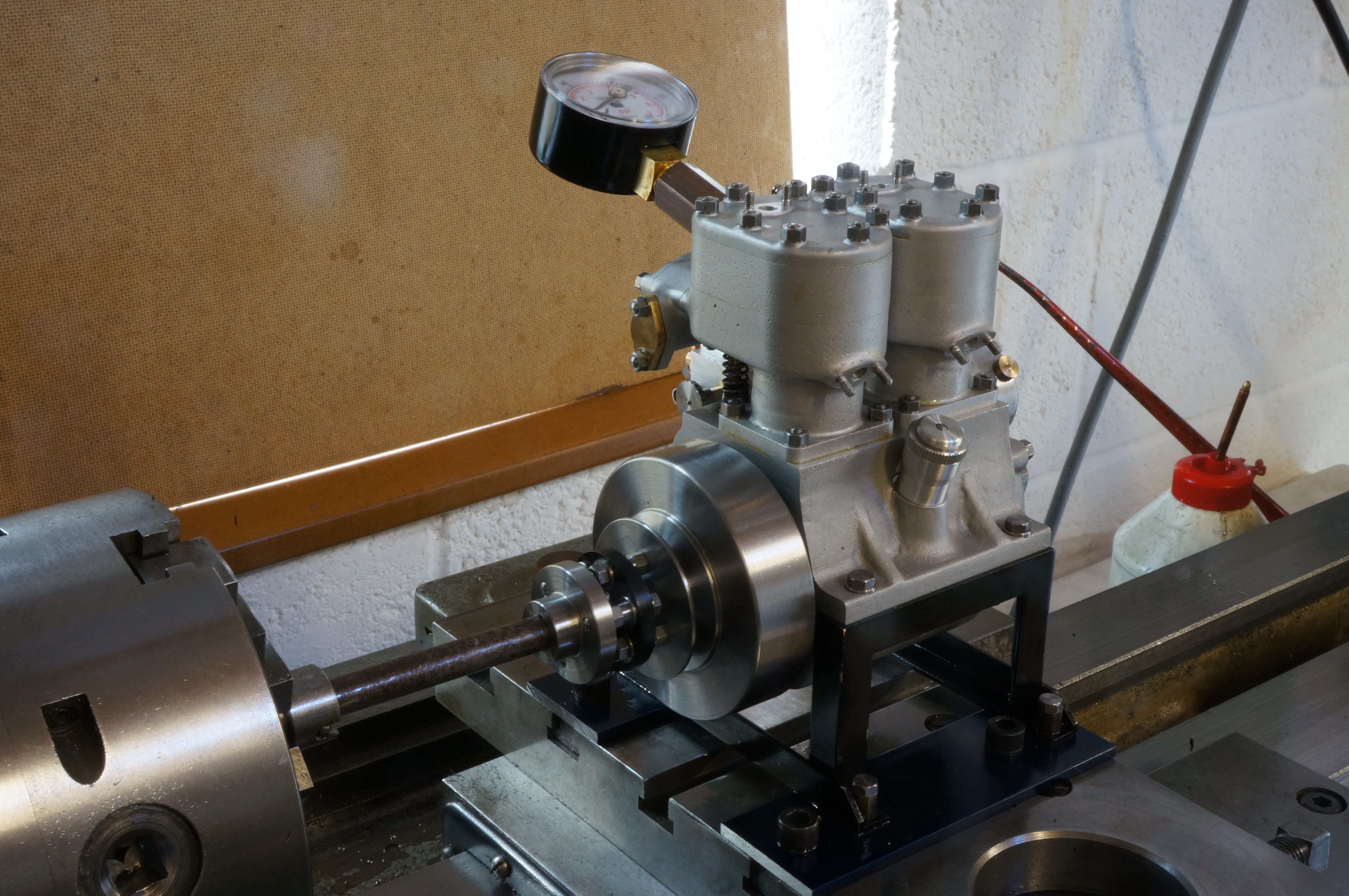
For motoring the engine over, I have a suitable variable speed drive with an adaptable mounting arrangement; in the form of the lathe. I re-fitted the flexible coupling to the flywheel, and made some mounting plates and spacers to allow the engine stand to be fixed to the cross-slide boring table. Running on and off, I seem to be getting plenty of compression on No2 cylinder, but little on No 1. The ball valve in the tester is only working sporadically. (3¾ hours)
2020-03-15 – Improving the breather
I have been motoring the engine occasionally for brief periods. The crankcase is breathing partly through the exit hole for the timing wire. I need to make a plug. Removing the timing cover it is good to see that there is oil around the top of the timing case. The magnets have collected a small amount of dirt. I made and fitted the plug, removed the silencer, and checked the tappet clearances.
I don't have a spring small enough to load the ball in the compression tester, but have found that putting a loose pin behind the ball helps it to to seat. At a nominal 625rpm I am now getting up to 54 psi on No 1 cylinder, and, very inconsistently, up to 38 on No 2.
The engine is chucking a lot of oil out, especially at the flywheel. I suspect the breather valve is forming an oil seal and the six holes are not providing enough area to break the seal and lift the valve. Rummaging in the engine's jig box, I found the chucking ring for the breather and cut a shallow annular groove to join the holes. This has made a big difference, and the breather valve is now the noisiest thing on the engine. I briefly tried a roughly made leather disc instead. It is certainly much quieter, and might do the job if better made.
I also modified the pin and ball coupling to take a Meccano shaft (8 SWG or 4.1 mm), ready for starter gearing experiments. (5½ hours)
2020-03-22 – Getting compression
Still motoring the engine, running at speeds up to 2000rpm for brief periods. Above 1500rpm it gets quite warm. I have put the plastic crankcase breather reed back, at least for now. I have reset No 2 exhaust tappet clearance, but it is still a bit on the high side at 0.003″
At 1500 rpm, I am now getting compression readings up to 50 psi on No 2 cylinder, and up to 70 psi on No 1. This is enough compression to be able to go back to the starter experiments.
Setting Up
With the basic engine now completed, I need to do a lot of small jobs before I can run the engine. The plan is to continue to use the lathe as starter motor and bed for early testing.
2020-10-10 – Making a temporary timing mark
To get an idea where to position the timing cover, I need a timing mark. It will be temporary at this stage. I wired up the hall sensor and TIM-6 ignition to use the timing light to show when the hall sensor switches on and off. Next, I made a timing pointer out of steel shim to fit on one of the cylinder mounting studs by the flywheel. I took No 1 cylinder head off and used a DTI to find top dead centre. Ball point makes a good mark on duct tape, so I wrapped a piece round the flywheel, and then took it off and re-wrapped it anticlockwise, so the tail would be trailing when running. I snapped the pointer while bending it to shape and made and fitted another one and marked the timing line on the tape. Finally, I cleaned up the head bolting faces and reassembled it with fresh Wellseal, and fitted the water outlet pipe.
There seems to be a slight difference between the two timing magnets as No 1 switches the sensor off about 1.5° behind No 2.
2020-10-17 – Plumbing
The first job today was to clean up the extruded sealant round No 1 cylinder head and the coolant outlet pipe flanges. Then I turned from solid a pair of brass adaptor flanges with hose tails, milled flats on the flanges, drilled them and fitted the outlet flange. The inlet pipe needs finishing.
2020-10-21 – Exhausting
After installing the coolant inlet pipe on the engine, I cut down some 8-BA screws to 9⁄32″ length and fitted the hose adaptor flange.
For the first runs, I want to be sure that both cylinders are firing properly. I removed the silencer, and the blanking plate from the opposite end of the exhaust manifold, and put a ¼″ reamer through the manifold to clear any bumps left over from drilling and tapping stud holes. I made a plug from ¼″ bar and fitted it with a smear of Wellseal to hold it in place temporarily. This ensures each cylinder can only exhaust out of its own end of the manifold. It turns out it was good thinking on my part to make the manifold open at both ends. (2¼ hours)
2020-10-31 – Canning
A stainless can of about 1pt capacity, a kitchen reject, will form the thermosyphon coolant header tank. I drilled 8mm holes near top and bottom for water inlet and outlet and made a pair of 5⁄16″ × 32 TPI nuts from 7⁄16″ A/F gunmetal hex bar, and made hose tails from brass. Tidying up. (2¾ hours)
2020-11-02 – Mounting the can
After some indecision, I used some non-silicone bathroom sealer to fit the hose tails to the can. I put tapped holes in both ends of a redundant foot length of 3⁄8″ mild steel bar and drilled a hole in the bottom of the can. There is a ¼″BSF tapped hole in the pivot pin of the Myford taper turning attachment, and a grub screw allowed the post to to be fitted to that handy position behind the bed. A bit of sealant and a cap-head screw fixed the can to the top of the post, to give some head to activate the thermosyphon. (2 hours)
2020-11-03 – Connecting up
Having tested the can for leaks and found it OK, I added the engine to complete the water circuit. The inlet pipe leaks at the swept joint. I am going to do something else while I think about that.
I am going to turn the engine round for testing, so that I have the carb and plugs to the front. I will need to couple the lathe to the timing end of the crankshaft. The drive will need a torque limiting device to protect the engine if it decides to seize up. I will also eventually need a coupling from the starter gearbox and am thinking in terms of a jaw and spider coupling. I have some 10mm thick white nylon and decide to see if that can be used to make suitable spiders. I saw out and mill a suitable rectangular piece to experiment with. This turns out to be more relevant to the starter, and I will cover all the jaw coupling work there. Meanwhile I also order a double hooke-joint coupling as an alternative. (½ hour)
(There is more unmissable excitement to go here!)
Test Running
2021-01-21 – First light
The engine ran for the first time today.
2021-01-22 – Early testing
A short early run. The engine is motored by the lathe via a sprag clutch (a form of freewheel) so that it can outrun the lathe, and a torque limiter to protect the engine in case it decides to seize up.
It took a while for the engine to lift fuel. The carb is still a long way off - too lean when open and too rich at idle. It also looks as though the choke will be needed, as I had to open the jet before the engine would start, and then screw down again as it warmed up and before it would run well. Once it was warm, I did not try to go to full throttle, I won't do that without a load. I have yet to learn how the engine wants to be asked to start.
The main difficulty is that circulation in the thermo-syphon cooling is hopelessly inadequate. After a couple of minutes running the cylinders are too hot to hold. I shut down this run immediately when I saw a bubble in the water outlet hose. I was expecting I would need a water pump, but not expecting the engine to heat up so quickly. I have a pump more-or-less designed.
At higher speeds the exhaust is blue, so the splash lubrication is working. There may be a bit too much oil in the sump, and hopefully the piston rings will bed in. As a precaution I might strip the engine down to check all is well before it gets much more running time. I think, and fervently hope, the horrible chirruping noise is coming from the cheap double-hooke-joint drive between lathe and engine.