
Exhaust Manifold
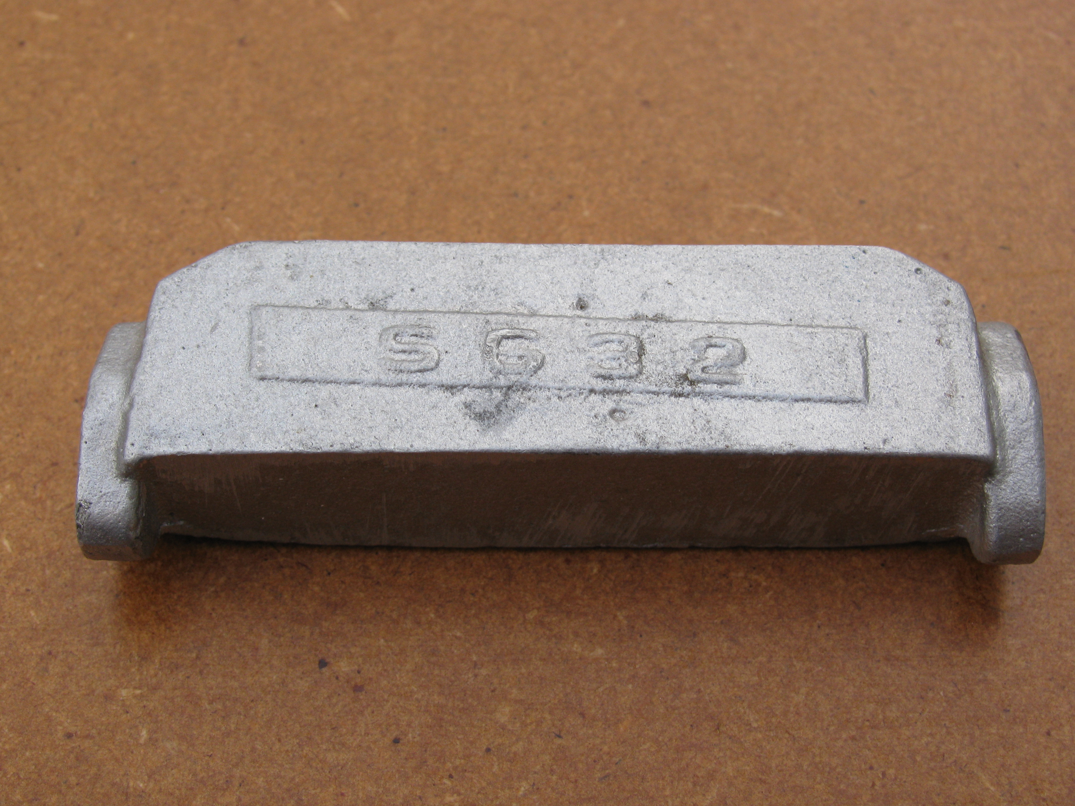
The draw on the casting means that one side will not clean up to the full ¾″ width. This side can be put at the back, against the cylinder ports, as the full depth is not needed this side. The top face of the casting could probably be squared up to remove the draw, which would look better. Although the end flanges are generously sized, their positions mean that it will be quite tricky to ensure they will clean up to size. They will probably want cleaning up by hand to match a template.
.
2010-03-13 – Trying out the castings
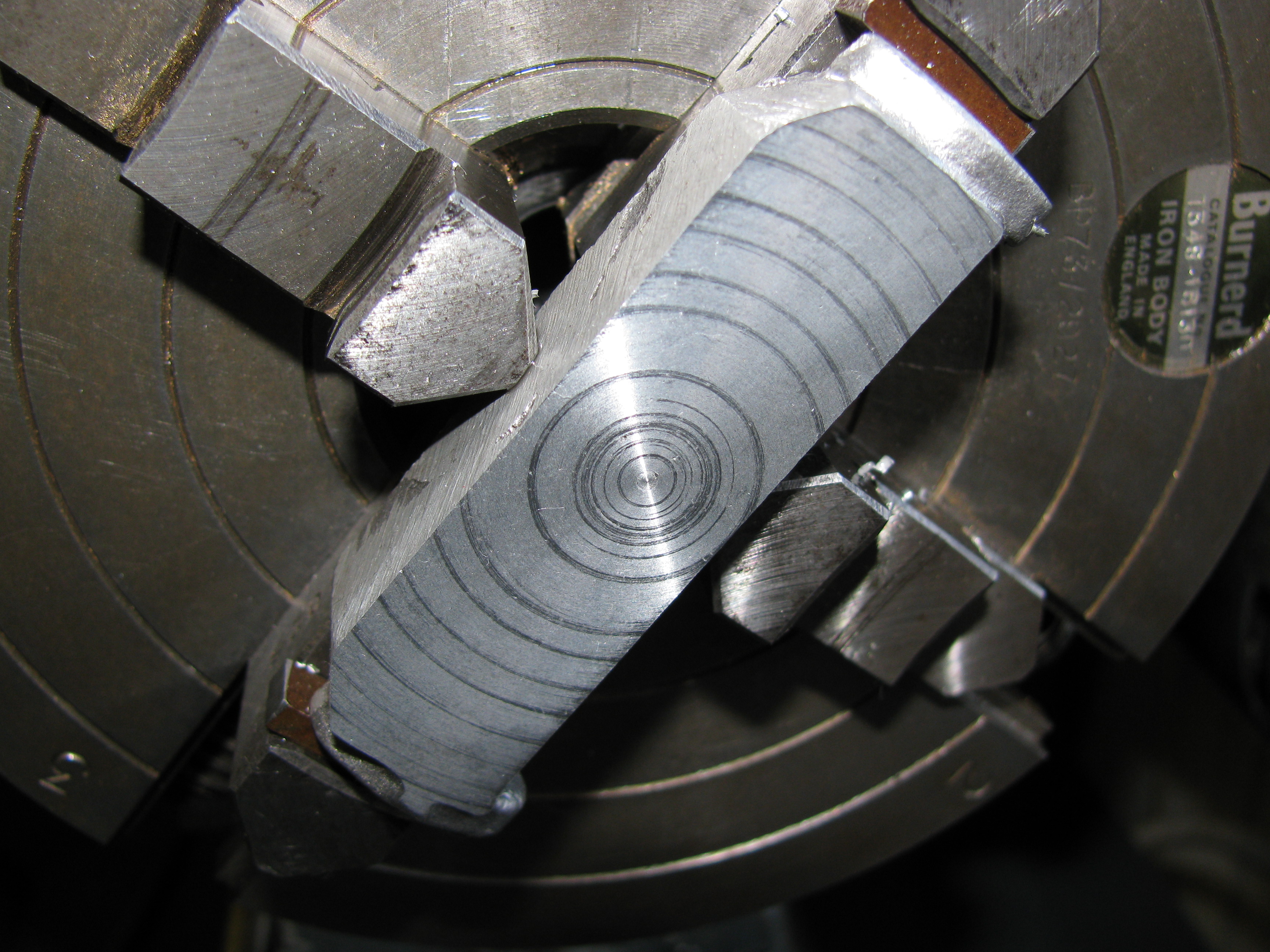
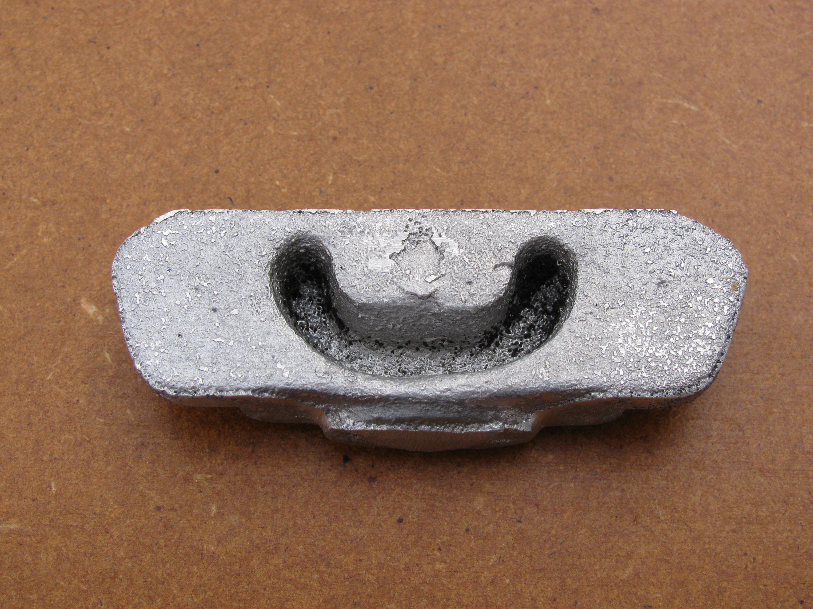
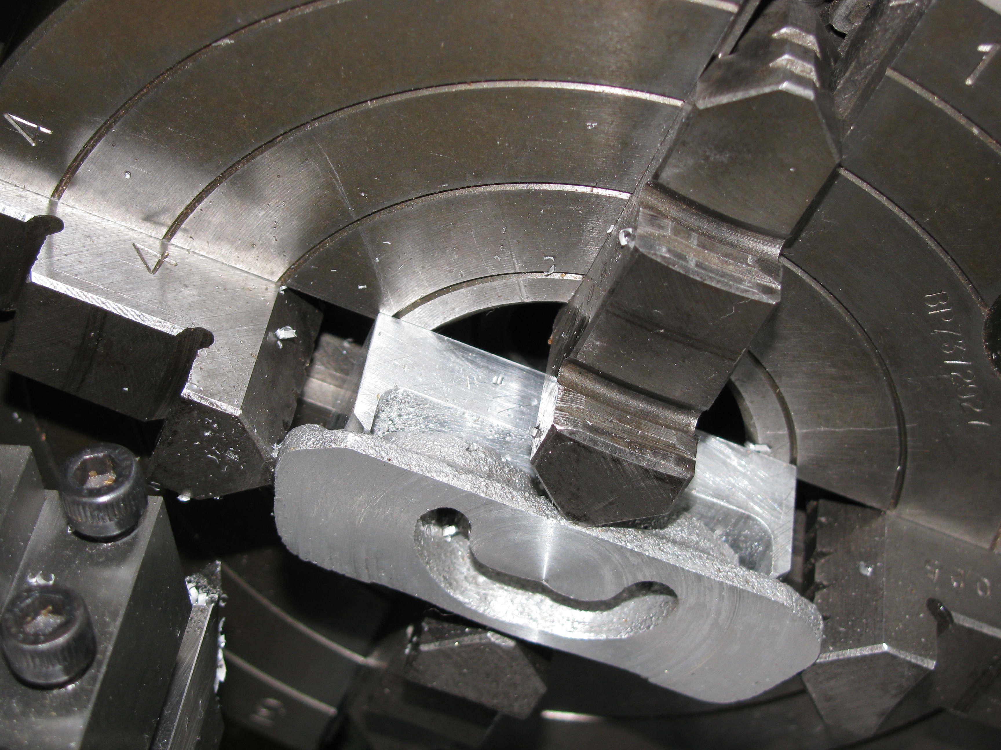
I was a bit worried about what Ron Chernich had to say about the castings so I decided to try a relatively simple one to learn on. The front face was rubbed on a coarse diamond whetstone to sit firmly on the top step of the 4-jaw chuck, packers made for the ends, and 30 thou taken off the back face. Should I use some cutting fluid or not? The result of periodic applications of paraffin diluted neat cutting oil from the washing-up liquid bottle was a series of bright rings on a smooth but more mat face. Generally the finish seemed quite fine.
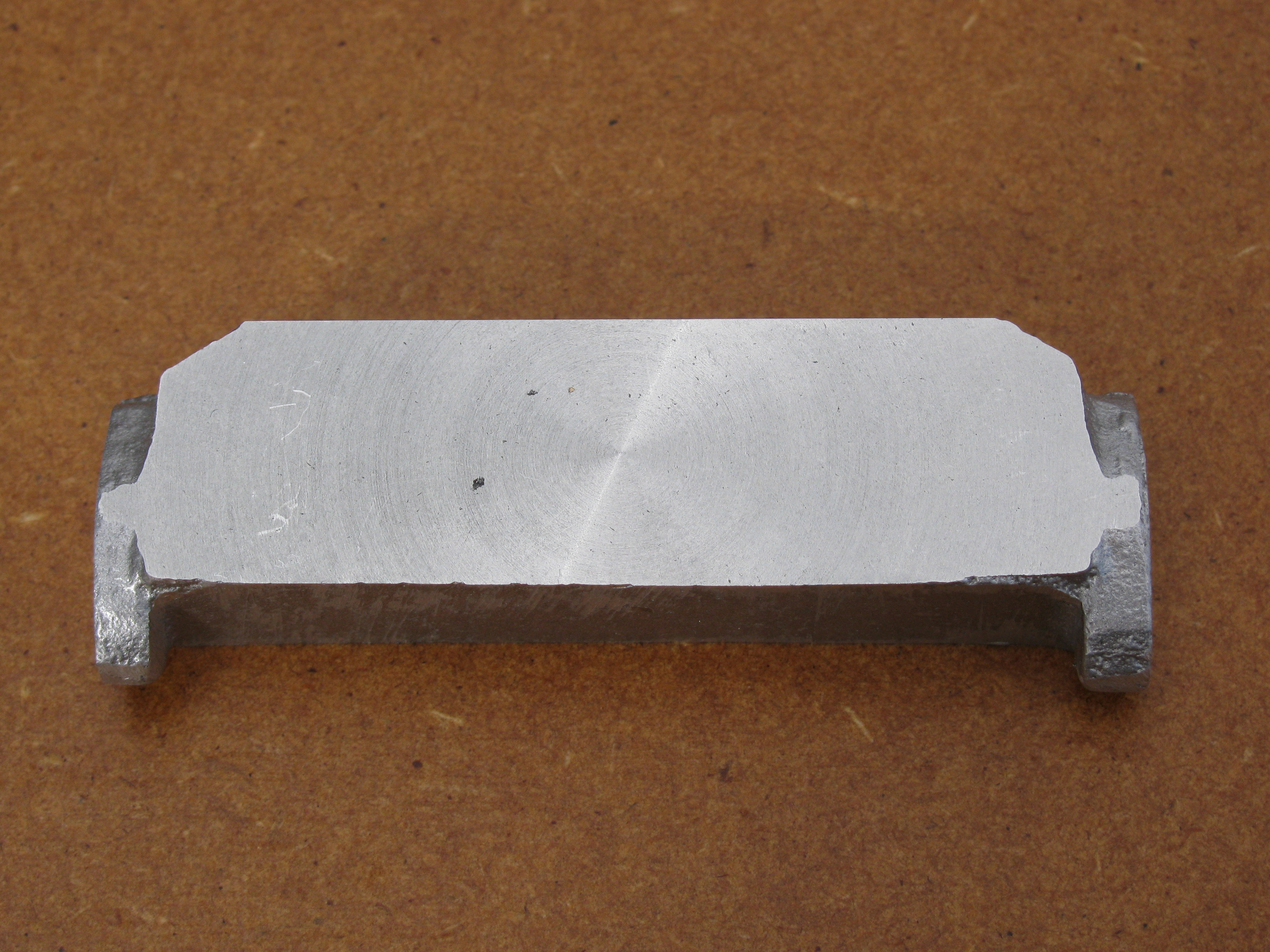
The job was reversed and the same amount taken off the front, this time working dry and taking a more aggressive cut. The surface was still perfectly acceptable. There are a few very small voids in the casting, but nothing to worry about. There is a tiny fragment of brass in the surface. It is more likely my dirty habits than an inclusion. The scratches at the left hand end are from packing strips; this is only roughed out, and the final face will be lapped flat.
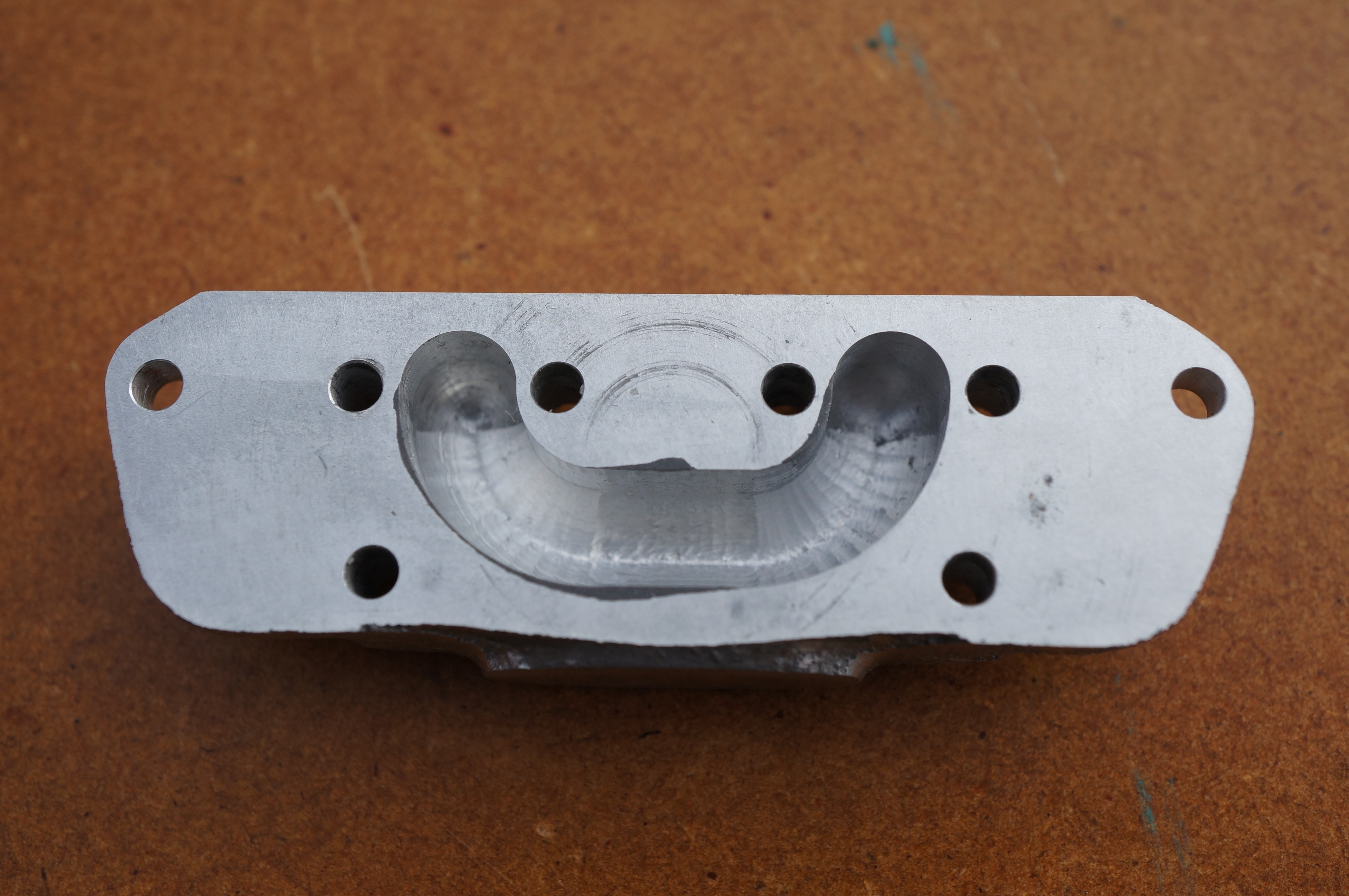
Next, the top was machined. I set it up with parallel packers under the bottom of the body, as this surface will not be machined, and protection strips for the machined faces. Two cuts, amounting to about 25 thou, were taken, the back edge not quite cleaning up. This time I tried a squeeze from the bottle of Rocol RTD spread out on the surface. This worked pretty well, remaining on the surface throughout the cut and producing a better finish than the dry cut. As this is not a mating surface it was rubbed on a piece of 800 grit to remove the machining marks and see how it comes up. Again the large photo shows tiny voids in the casting, not any where near enough to cause porosity. The first of the flanges was then tackled, again in the 4-jaw, with protecting strips on each of the machined faces, and a shorter piece on the underside, unmachined surface to ensure even pressure against the opposite jaw. About 25 thou was taken off.
Experimentally, I lapped the back face on a fine DMT diamond whetstone borrowed from the woodworking department. A good surface soon appears, but it is difficult to avoid scratches from particles trapped in the surface pockets of the stone. (1½ hours)
2010-03-14 – Flange check
After facing the second flange, I checked the profile with a paper template cut from a copy drawing. It looks as though there will be just enough metal to clean these flanges up. Good. Let's have a go at the crankcase.
The front and back faces will just clean up to the 27⁄16″ length shown in the drawing, but I was hoping for a bit more than this. It only allows a 3⁄32″ radius round the outer studs, or 0.037″ metal thickness round the clearance hole, not enough for a proper seating of a 6BA nut. I don't understand why Westbury made this so tight. (½ hour)
2014-09-29 – Setting up
My last job today was to check the metal to be removed from each side and set it up for facing the back. It needs 0.025″ off the back and 0.020″ from the front to leave a lapping allowance on the final 7⁄16″ thickness. (¾ hour)
2014-09-30 – Facing the back
In a very short session today, I took a roughing cut of 20 thou and a finishing one of 4 thou. The manifold was obviously not properly bedded against the chuck as, although there was only 0.0005″ in it from end to end, there was a variation of 0.0015″ across the ¾″ from to to bottom. I need a more careful set-up for finishing the front. It looks as though the machined back face is unlikely to fully cover the cylinder port faces at each end. (¼ hour)
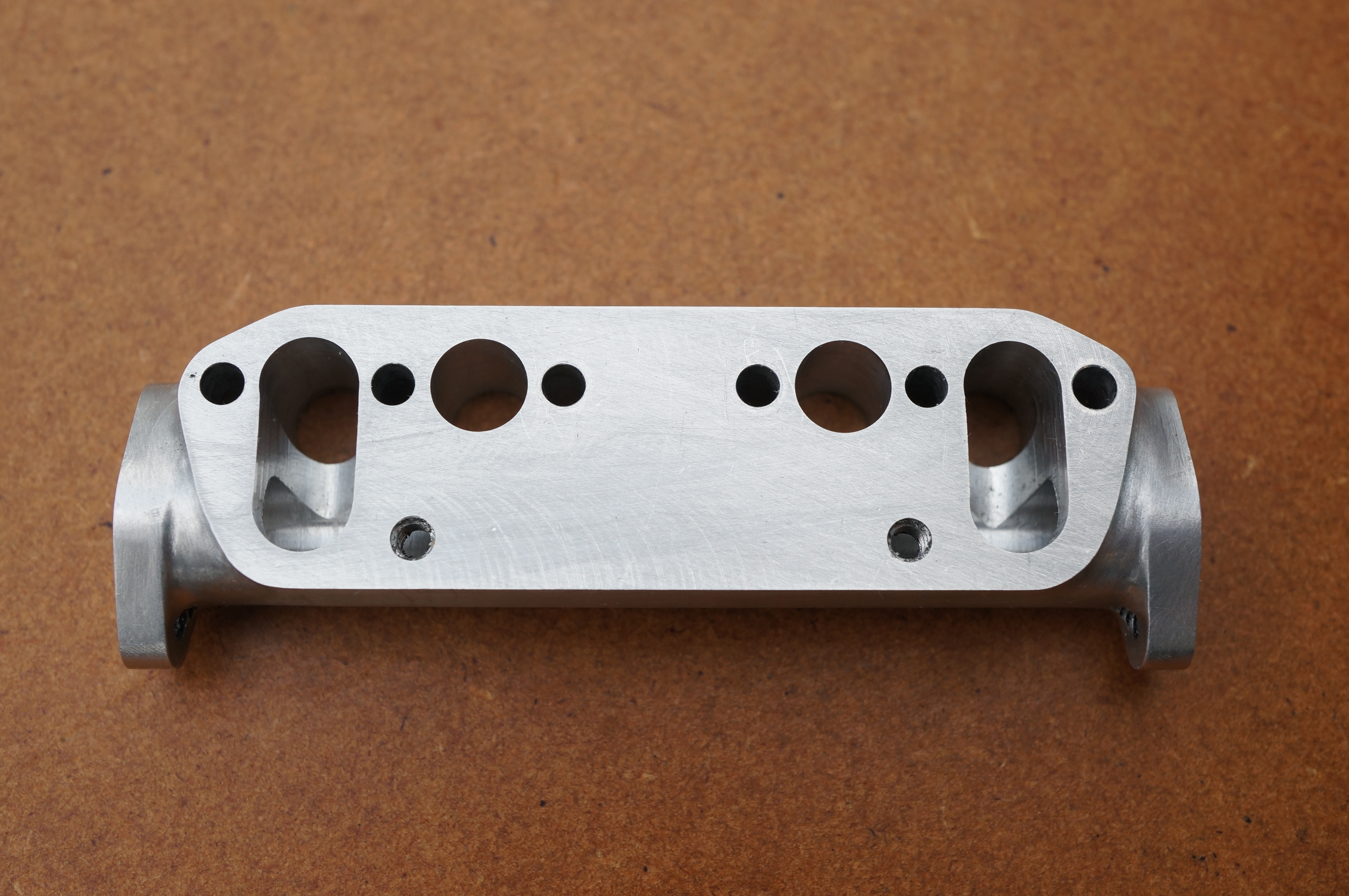
2014-10-01 – Facing the front
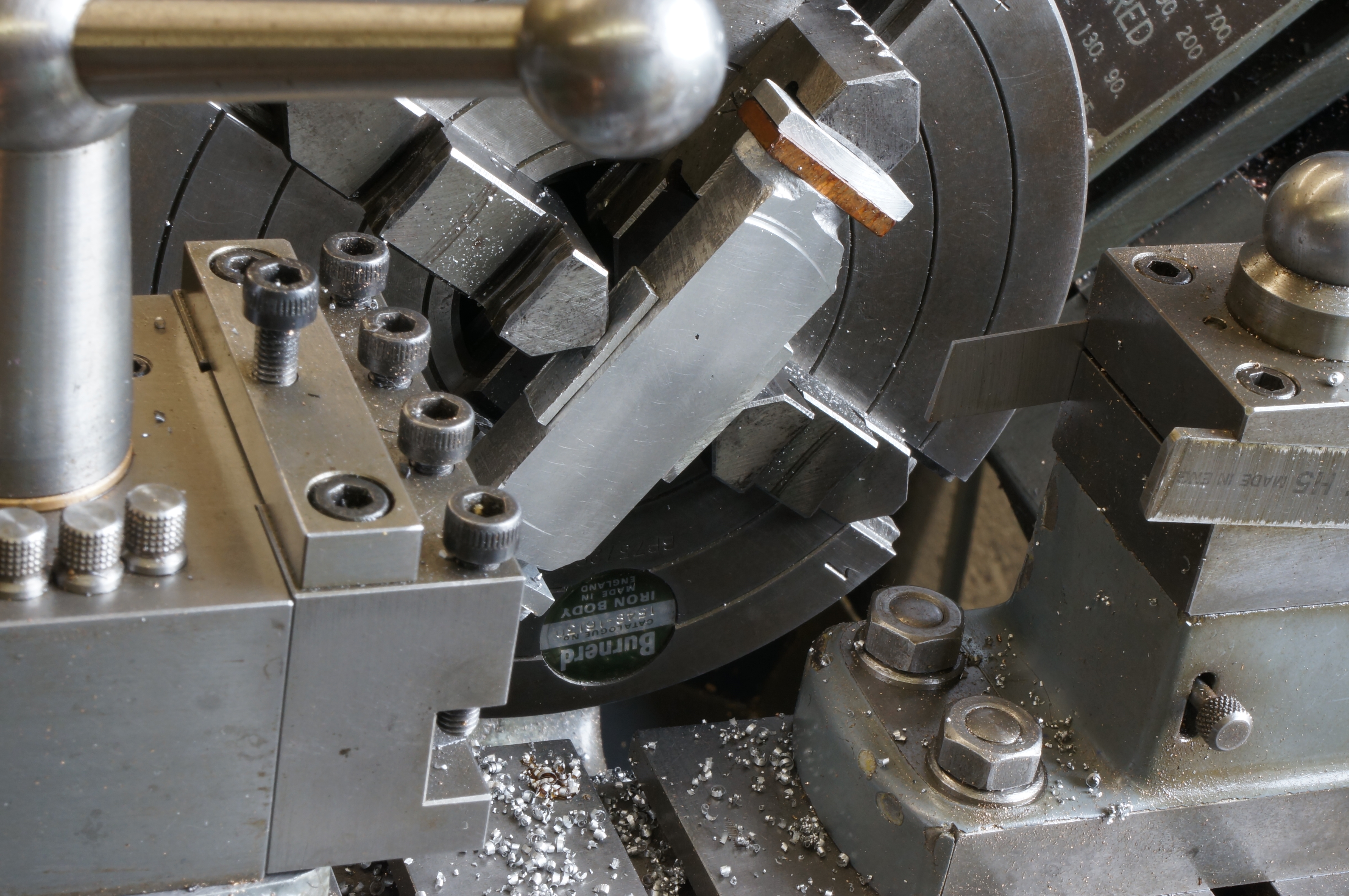
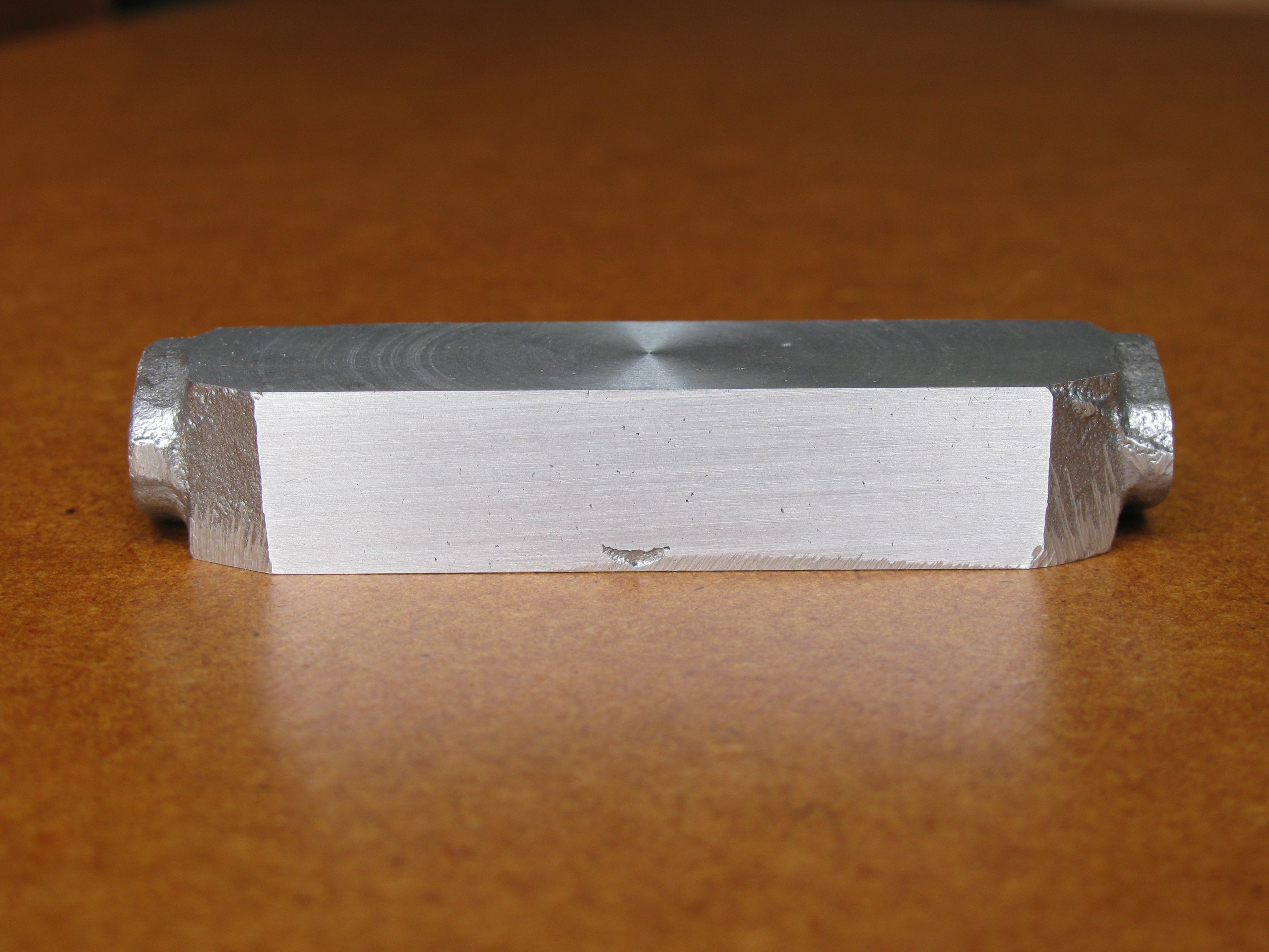
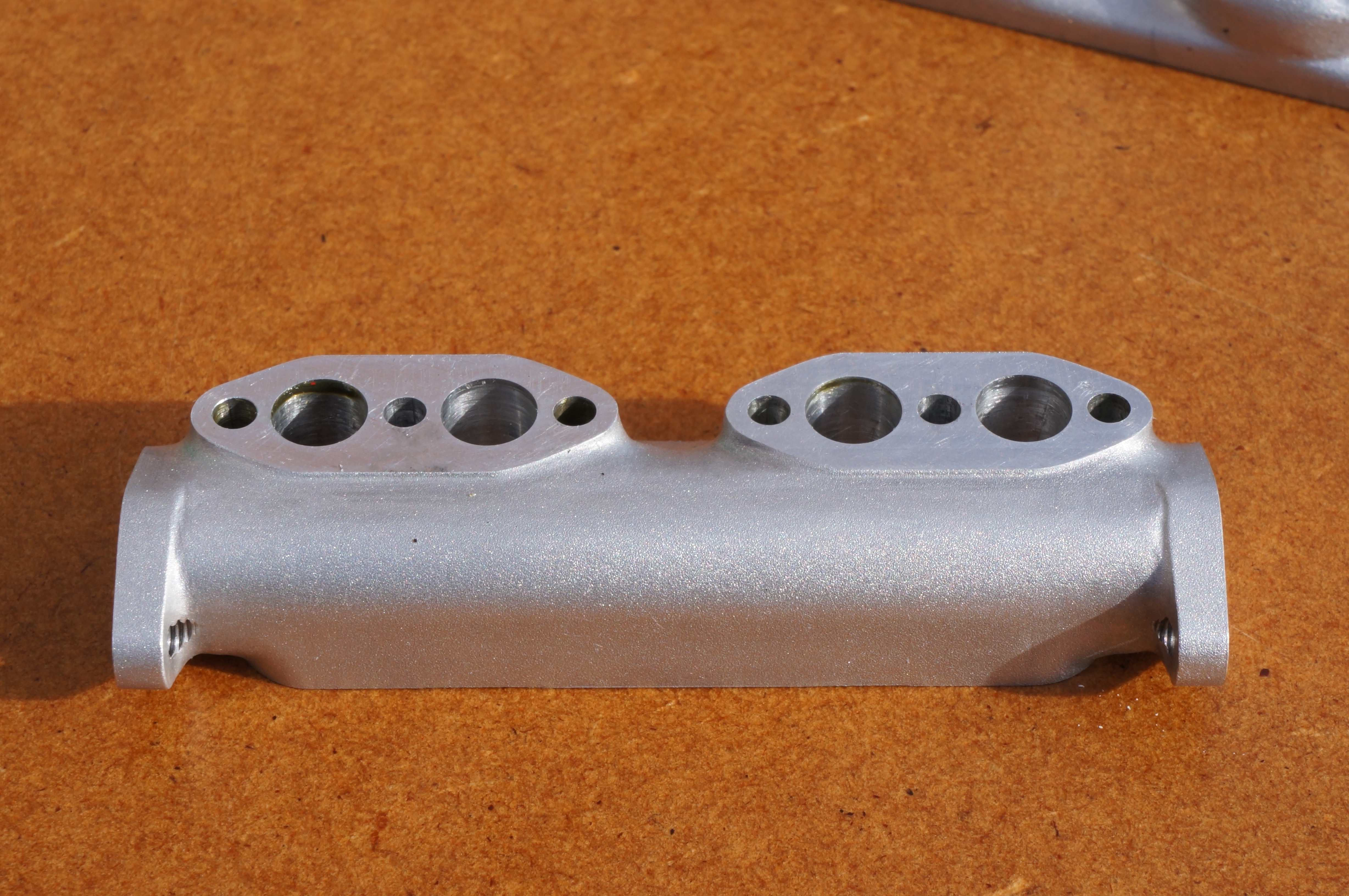
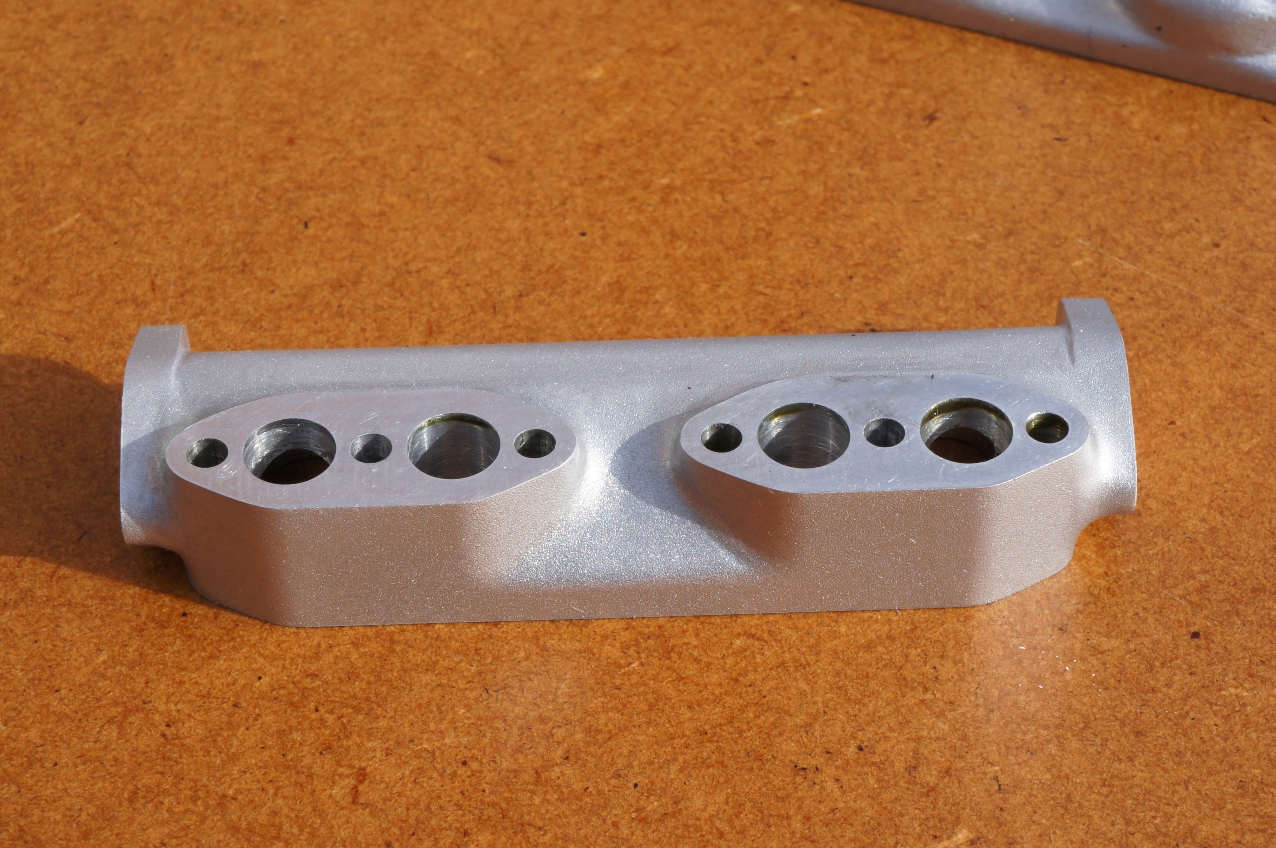
I have decided to add 1⁄64″ to the thickness. This will make it easier to differentiate between the machined front and back faces and the 'cast' surfaces of the flanges at each end. This means I want to machine it to 0.455″ thickness. The witness marks (in the photo) from setting the tool show I have got the back face better seated this time. It turns out within ¼ thou across the face this time, but a bit less than 1 thou out end to end, with each face dished by about ¼ thou.
The bolting face for the inlet manifold measures 2.430″, some 0.040″ short of what would be needed for 7⁄32″ diameter bosses on the inlet manifold. The back is also 0.025″ less than needed. If there is any discrepancy between the positions of the two faces, that will make matters worse. There is about 0.020″ available to machine the end flange faces, and this looks to be distributed evenly except for the lugs underneath which differ in thickness by about 10 thou.
This casting would, with great care, just machine to the original drawing. However I would really have liked more metal round the stud holes. I am not sure how to proceed, but the answer seems to be to press on. If I don't like it, I can start again. I may be able to reduce the boss diameters a bit, but that would depend on the Inlet Manifold, so back to that next. (1¾ hours)
2014-10-10 – Starting again
Work on the Inlet Manifold has persuaded me that I can have a better job by starting again. I have redrawn the manifold to allow just a bit more room. It is 1⁄16″ longer and 1⁄32″ wider and I have enlarged the end flanges a little to allow the ¼″ bore to be extended through the exhaust pipe by accommodating a 5⁄16″ OD pipe. The 'cast' flange will be 10 thou larger all round than the nominal profile, as I have done with the water flanges on the cylinders.
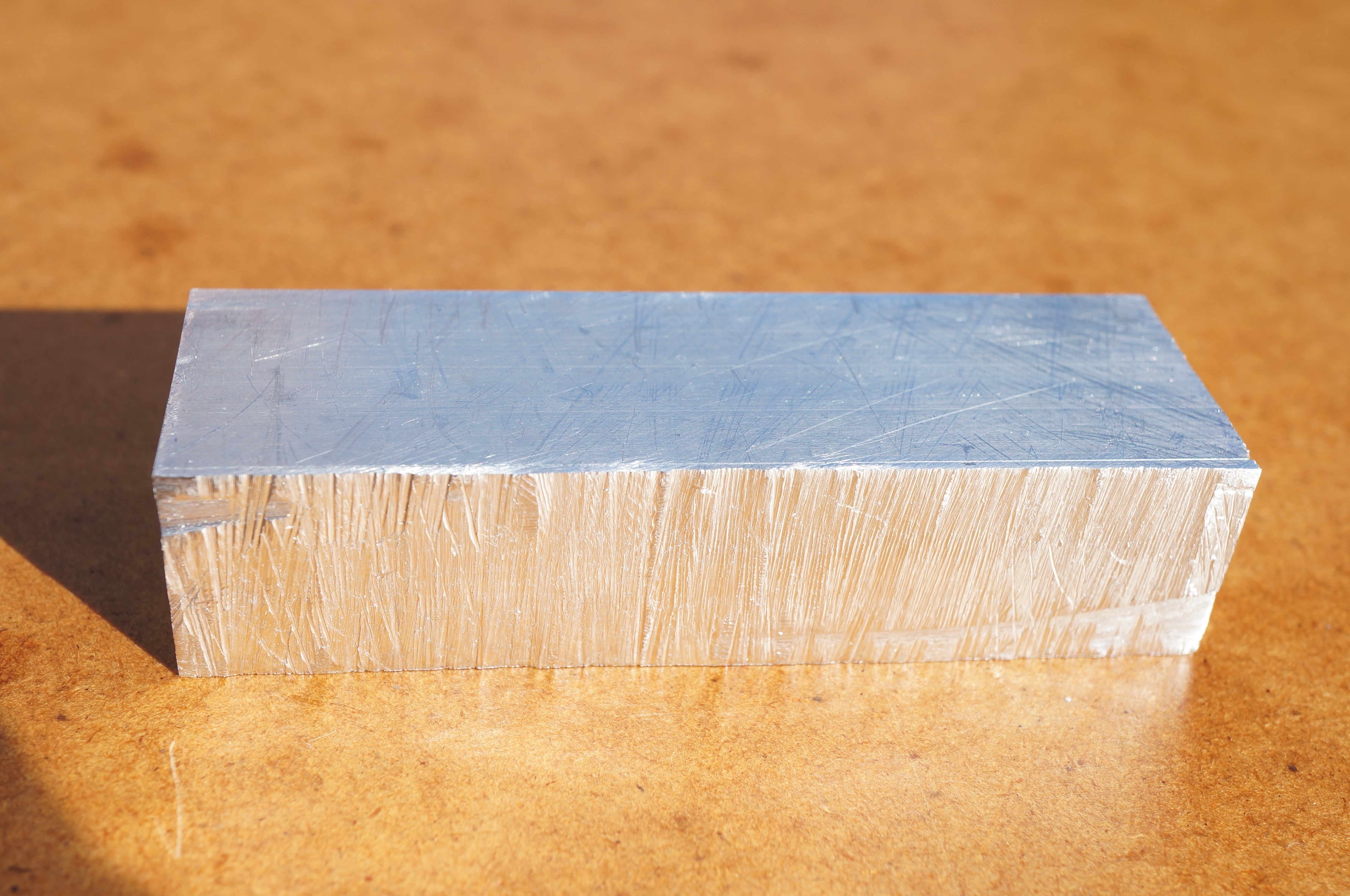
I have some suitable ¾″ thick alloy bar, so I cut out a piece 3″ × 15⁄16″. I milled the top face and then half the excess thickness off one side in two light roughing cuts and a finishing cut of 0.005″, and similarly on the second side, all the while measuring carefully for size and parallelism, leaving it at 15⁄32″ + 0.0025/0037. Next I milled the bottom face to a height of 0.920″, which leaves a few thou for hand finishing the end flanges. Transferring to the 4-jaw chuck in the lathe, I rough faced the ends, leaving about 10 thou each end for finishing. (4¼ hours)
2014-10-11 – Making holes

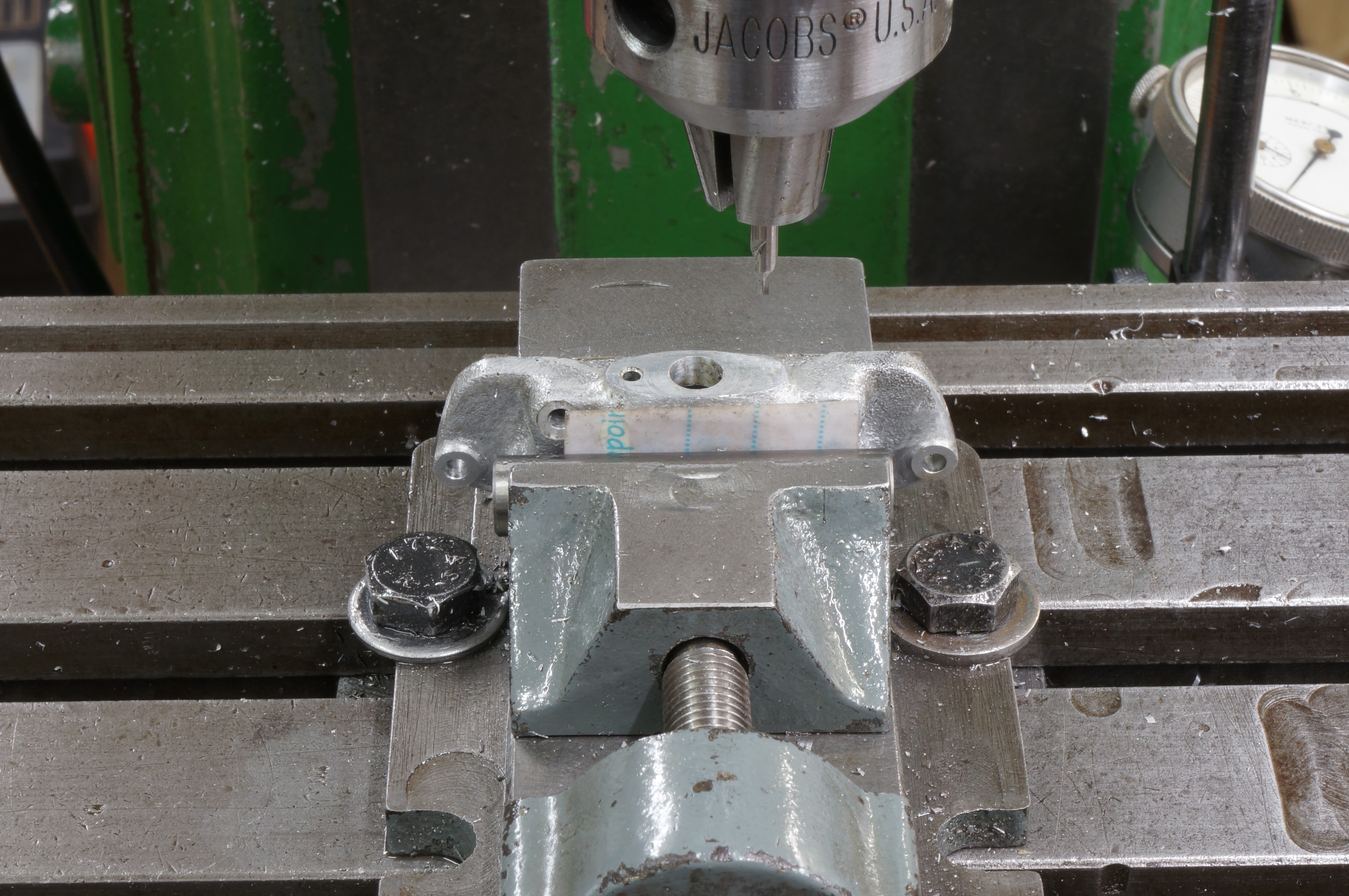
To set up the correct centre for drilling the hole that runs the length of the manifold I could mark out, centre-pop and use a wobbler and DTI, I could use a DTI directly to measure on the flats, or I could use a toolmaker's button set with slip gauges. I used the first method to get it roughly true, and then corrected it with the second. The centre pop turns out to have been about 4 thou out side to side and 1 thou from top to bottom. By setting the dial to zero on the sides, I had worked out I needed a reading of 0.297″ on the top face.
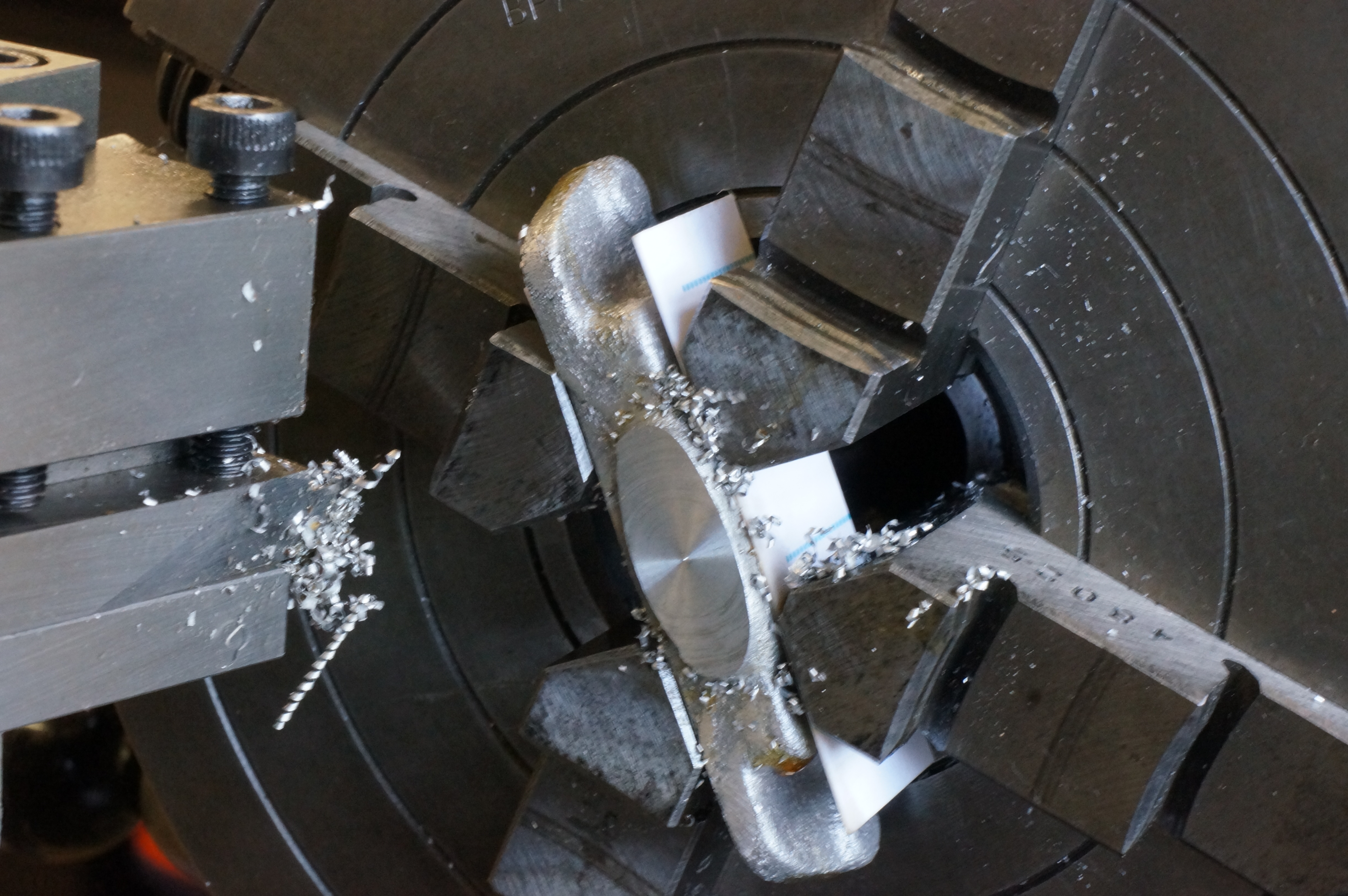
I took 0.010″ off the face, turned the flange to 0.775″ for 1⁄8″, deeply centred and drilled 5.8 mm to 1½ depth. Next I took a 4 thou cut with a boring tool to 1″ deep to ensure a true running hole. This was a nice fit on a 6 mm drill which I took to the bottom and followed with a 6.2 mm one. This was all done at 1000 rpm. I then dropped to 290 rpm and reamed ¼″. On removal, it measured 2.761″ long, so to allow 1 thou each end for lapping, I will need to face 9 thou off. I set it up again the other way round and repeated the procedure.
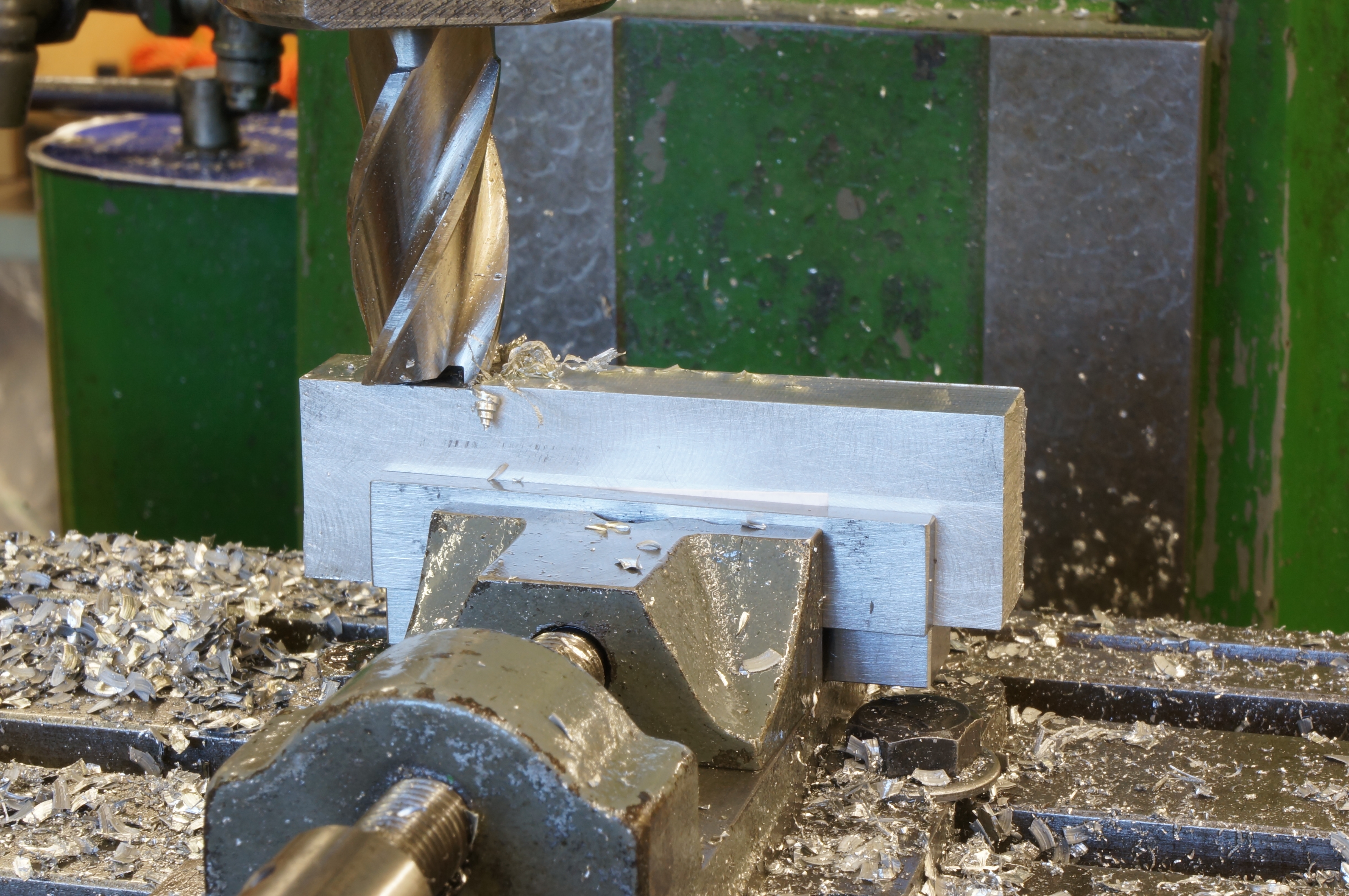
Next I set the manifold up in the milling machine for the bolt holes and ports. I drilled the top row of six mounting holes 2.8 mm, and then drilled and reamed the four ports ¼″. I drilled the bottom two holes to 2.2 mm for tapping, with little counterbores, breaking into the longitudinal hole a short distance. Finally I milled the connecting exhaust slots with a ¼″ ball-nose cutter.
After cleaning up and deburring, apart from tapped holes in the end flanges, the manifold is now functionally complete. I just have to make it look like a casting. (5½ hours)
2014-10-25 – Making buttons for templates
I turned silver steel buttons for the end flange template 0.238″ & 0.458″ diameter, and 3⁄8″ ones for the carburettor flange on the inlet manifold, then hardened all the buttons.
Next, I cut two pieces of 3⁄32″ gauge plate for the flange templates, milled each one rectangular, and drilled them. (7½ hours)
2014-10-27 – Drilling & tapping
Today I drilled the stud holes in the end flanges, and then tapped the eight holes in total on both manifolds, using some new 6 BA taps, as the 40 year old ones seemed to be getting a bit tired. (2 hours)
2014-10-28 – Milling the underside
With the manifold bolted to a clamping block, I milled between the flanges on the underside, initially with a 5⁄16″ slot drill, and finishing with a 3.5mm long series cutter to get the internal radius. (2¼ hours)
2014-10-31 – Making templates
The filing buttons for the exhaust flange template need flats so they will fit together. Rather than milling before hardening, I decided to grind these flats, which I have partially done, and then let them cool down while I worked on shaping one side of the carb. flange template. (1 hour)
2014-11-01 – Carving begins

This morning, I finished grinding the buttons to fit, finished filing the two templates, and hardened them.
In a first session working on the exhaust flanges, the right hand (flywheel) end is well on the way.
The original design is a rather crude block. I want a treatment at the back and between the cylinders that will look more like an authentic manifold casting, with less unnecessary metal. (5¼ hours)
2014-11-04 – Filing and milling
After some more filing, I decided the back needs to be relieved before I go any further. I milled 1⁄64″ off the lower part of the back face and a groove up the middle to leave two rectangular pads for the port bolting faces. I then filed a 7⁄32″ radius along the bottom back edge. I worked on defining the lower corners of the inlet manifold, as this will provide a template for the blending the front face of the exhaust. Still working at the right hand end of the exhaust manifold, on the fillets where the port face and exhaust flange shapes intersect. (4 hours)
2014-11-08 – More filing

The filing today moved to the left hand (timing) end of the exhaust manifold. By the end of the day both ends were finished. (5¾ hours)
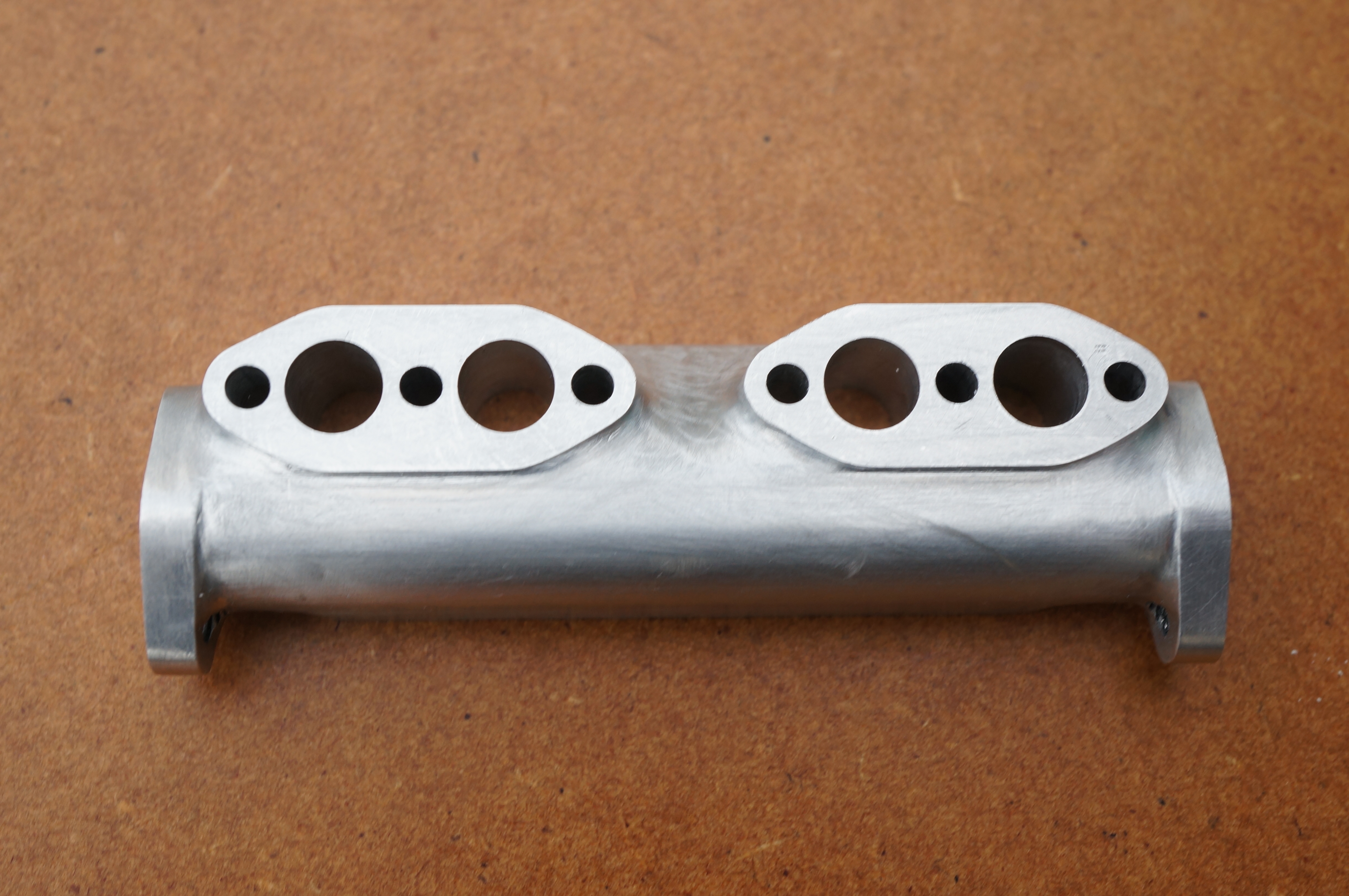
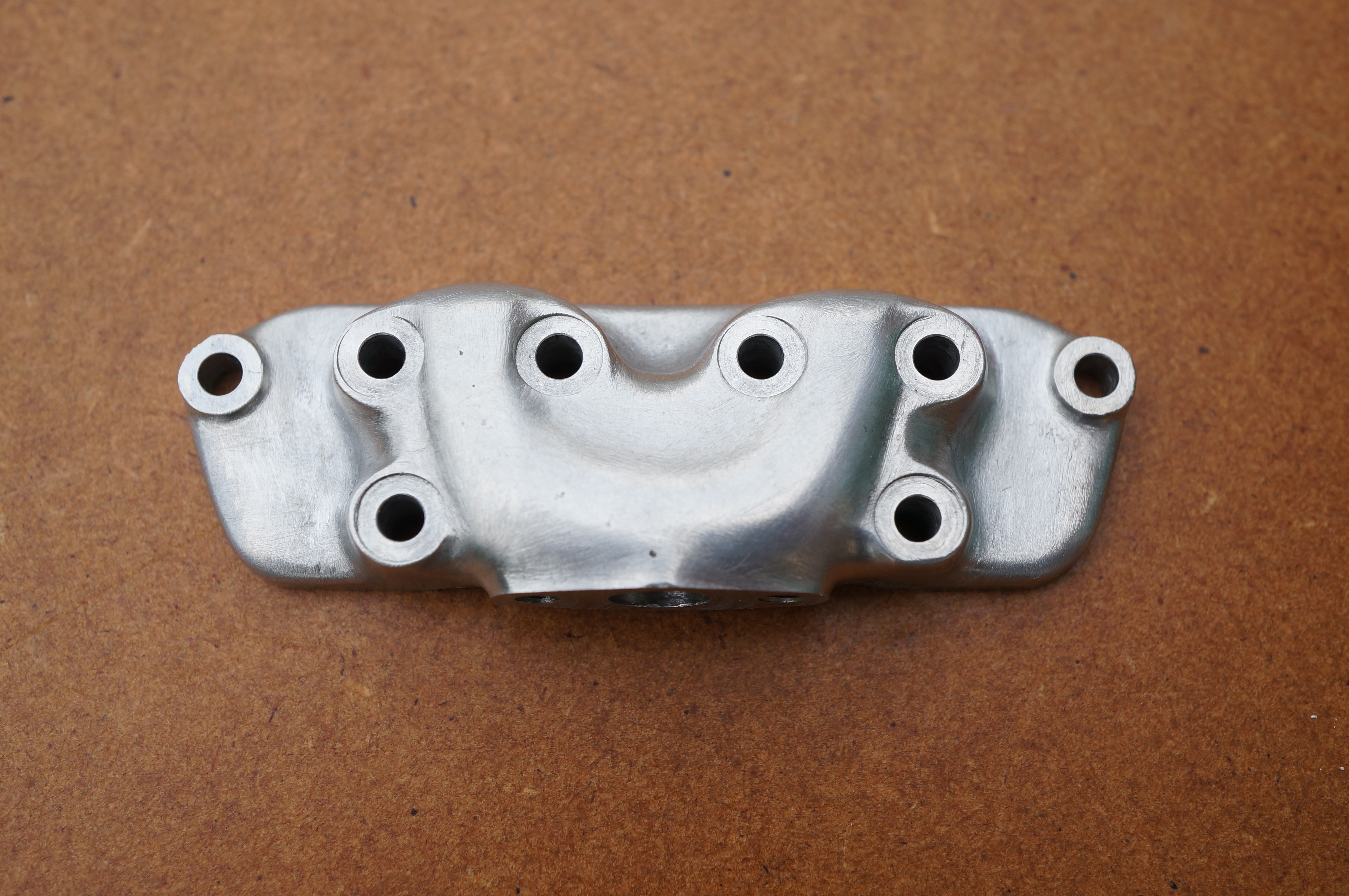
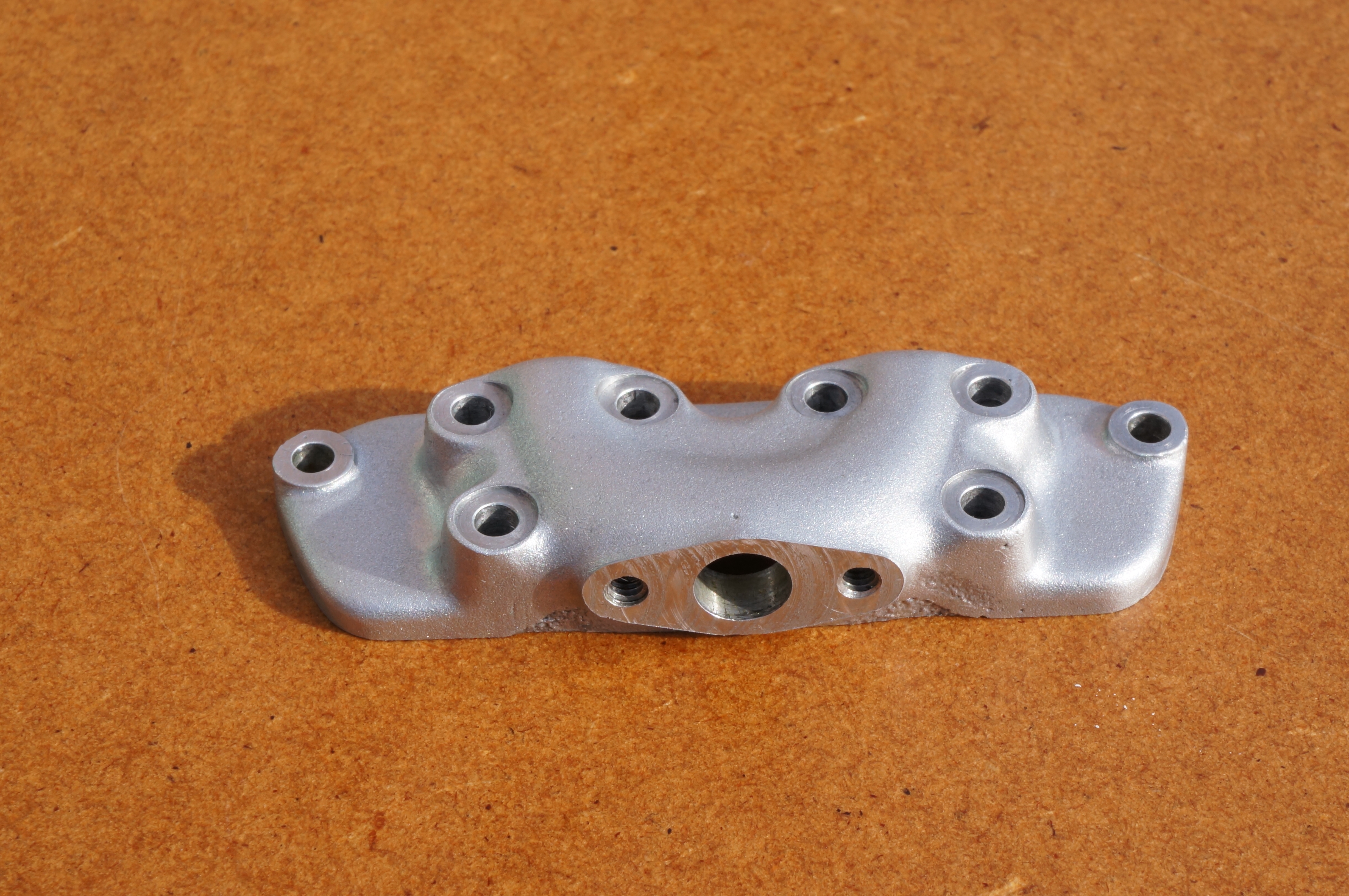
2014-11-11 – Sculpting the middle
Having decided to cut away at the back, between the two port faces, I made a start with a coarse round file, but did most of the metal removal with a carbide burr in the Dremel. I then refined the shape with fine files and round riffler, and then gave the whole job a final titivating with fine wet-or-dry paper. All it needs now is bead blasting. (3½ hours)
.
.
Inlet Manifold

Surprisingly, this fiddly little casting looks as though it is pretty accurate. The passage will want a bit of careful treatment, as it is knobbly and has quite a bit of sand still adhering to it. This wants doing before machining to ensure the delicate sealing face does not get scratched. There is very little metal at the bottom edge of the passage, meaning the casting wants to be set as high as possible. But here is also very little metal to clean up the carburettor mounting flange, meaning the casting wants to be set as low as possible. Machining the face first, and then the flange to a just sufficient area will determine how this works out. The positions of the cast-in bosses on the face will also have a bearing on the matter. To get the flange an equal thickness all round, it will want supporting on narrow parallels. It may be necessary to make a cradle to hold it. The top edge will probably need machining to match the exhaust manifold. The top row of bolt holes will be taken from the exhaust manifold, spot-faced from the front afterwards.
.
2010-07-17 - Making a cradle jig
I decided a fixture was the way to get an even thickness. After cutting out a piece from stock yesterday, I milled the cradle all over today. The support legs are a bit on the thin side so I used a ball-nose mill to avoid a sharp section change at the root. (3¼ hours)
2010-07-18 - Facing the bolting face
Used the fixture to machine the face to finished thickness. As expected, the cast shape of the port cavity has resulted in a sealing face width that is a shade under 3⁄32″ in one place. (1 hour)
2013-02-02 - Investigating the Carburettor flange
While doing preliminary work on the Carburettor casting, and while I had the 4-jaw chuck on the lathe, I decided to investigate the manifold to see if there was any scope for increasing the bolt hole centres on the carburettor flange. Machining this close if not to finished dimension was just sufficient to clean up a face long enough for the original flange, and still a bit short on the width. Exactly how best to get the finished part out of the casting is still in question, and the next feature to contribute to the decision is the boss at each end for the outer-most bolts. These will probably give a bit of vertical latitude by cleaning up larger than necessary. If so they can be subsequently cosmetically dressed to be concentric with the bolt holes.
I have decided to mill the inlet tract, to get the full flow area, a smooth surface, and as nearly equal distribution as possible. I am thinking of using some JB-Weld to fill the deficient parts of the cast passage. (¼ hour)
2013-02-04 - Spot-facing the end bosses
To allow this casting to be further assessed, I machined the spot faces on the outer bolting bosses. As it turns out, they will allow very little scope for adjusting the casting position. The tops of the two inlet tract bulges look as though they will provide a datum for getting the casting level.
2014-09-29 - Milling the top edge
Still exploring this casting, I milled 20 thou off the top edge to get a datum, then after further careful measurement, I took another 0.0075″ to final size. (1¼ hour)
2014-10-01 - Drilling
Firstly, I made a pair of filing buttons for the outer holes. Using a collet, the 7⁄32″ silver steel ran out by only half a thou so they just needed facing, drilling and parting off.
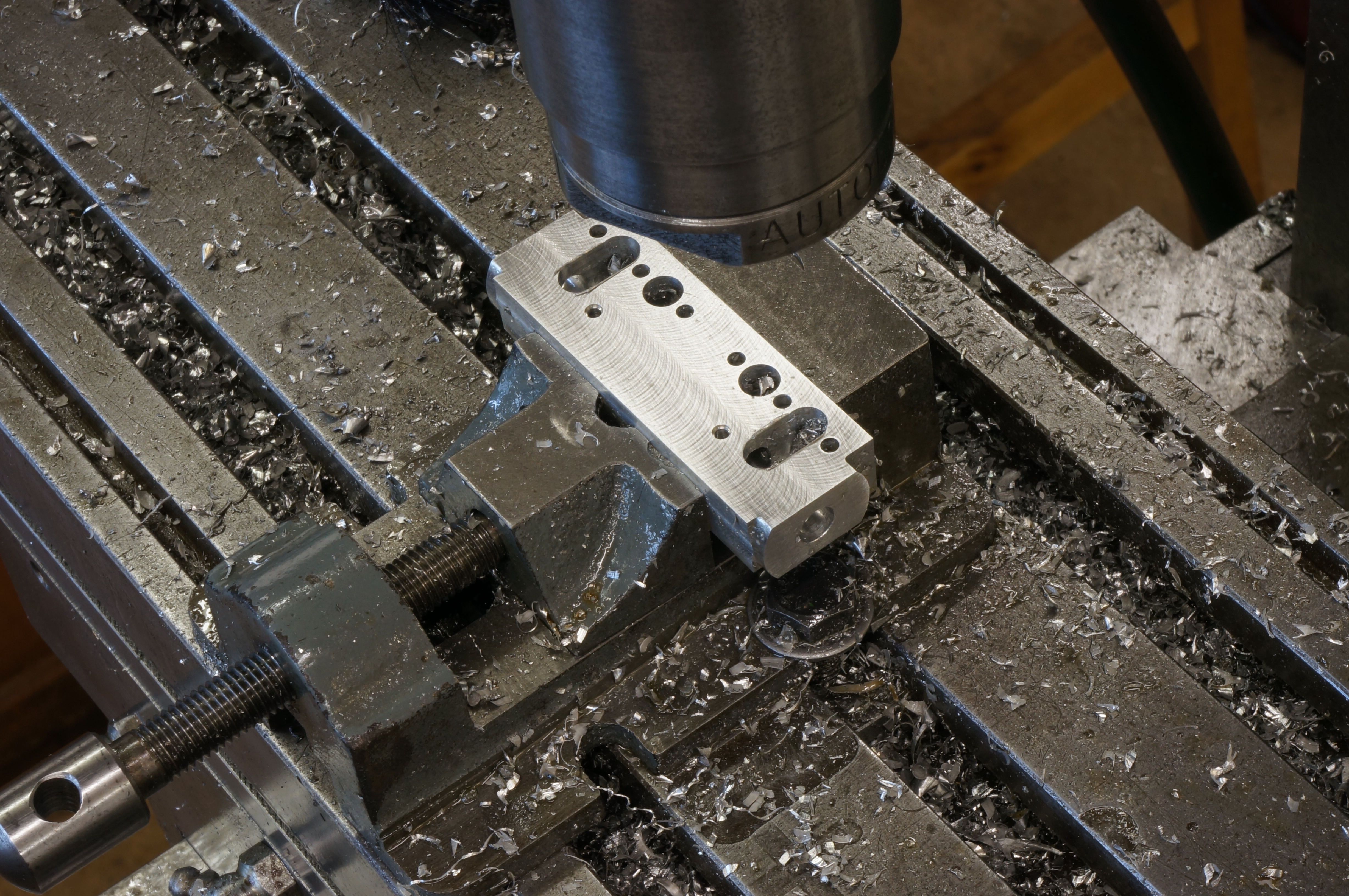
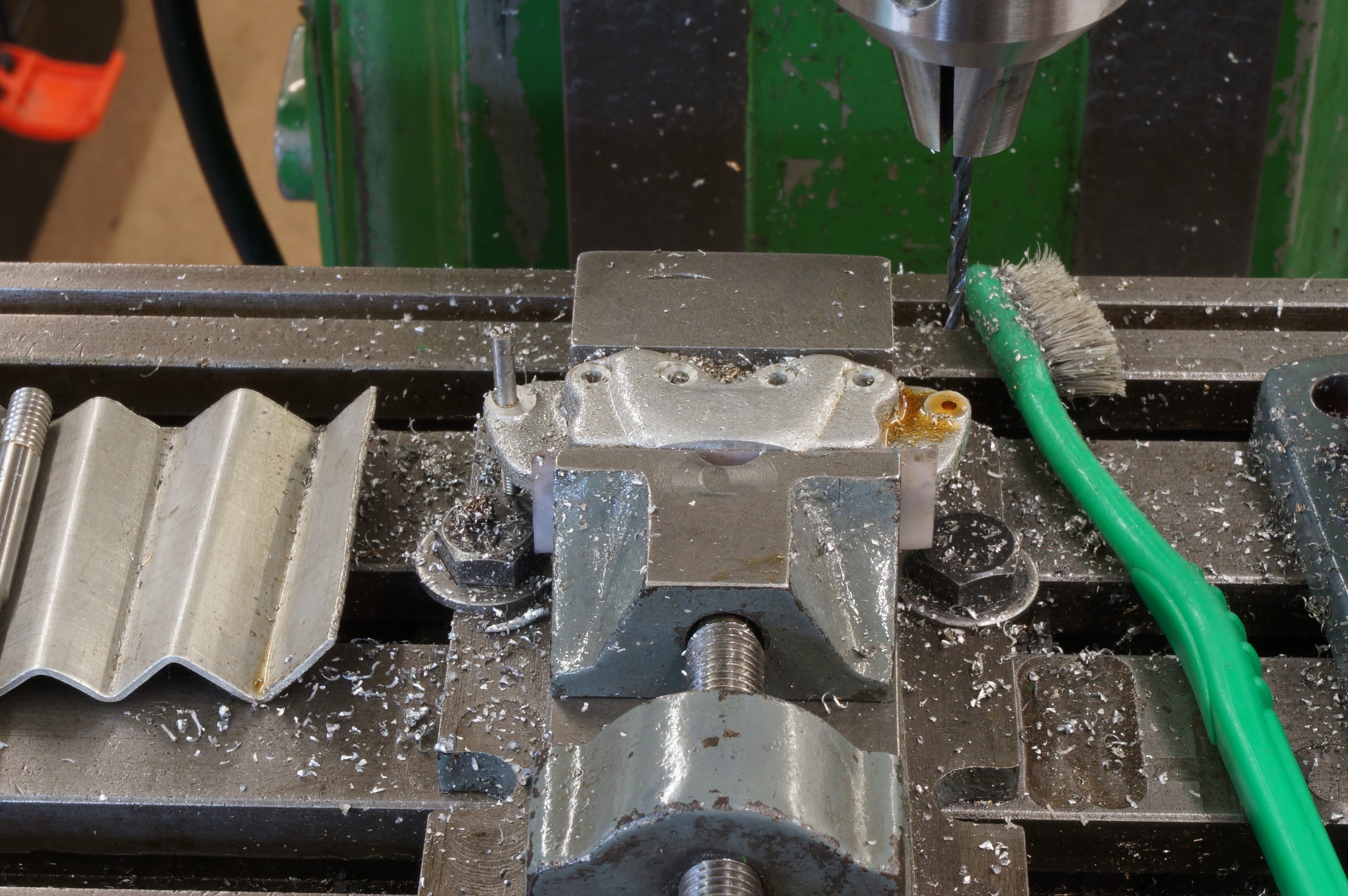
Next I set up in the mill to do the mounting holes. Being a bit suspicious of the milling machine y-axis dial readings, I set up a DTI to check it. It is about 0.010″ out on the small distance from the top edge to the hole centre line. There seems to be something wrong, but I will deal with it when the mill eventually gets a proper strip down. I drilled the six holes in the top row, spot-facing the middle four, and then went back over the spot faces, taking another 0.005″. After drilling the bottom row, cleaning up and deburring, I tried the manifold over the studs on the partially assembled engine. The holes are drilled 2.8 mm so they have very little clearance on the studs, but, with a bit of wiggling, it fits over all eight. I am happy with that. Also the carb. mounting flange is accurately centred.
Comparing standard 6 BA nuts with ones having 7 BA hexagons, I conclude the manifold will look better with the small ones. (3 hours)
2014-10-04 - Filling
Looking at the joint face, the cored inlet tract comes close to one of the holes in the top row, with only about 0.020″ between. Taken with the shortage of metal above the carb. flange, this confirmed my decision to use some epoxy to make up the missing metal. I gave the manifold an ultrasonic clean and filled with JB-Weld. (¾ hour)
2014-10-07 - Tooling
I made some spacers to support the manifold on a jig for milling out the inlet tract. (1 hour)
2014-10-08 - Milling the inlet tract

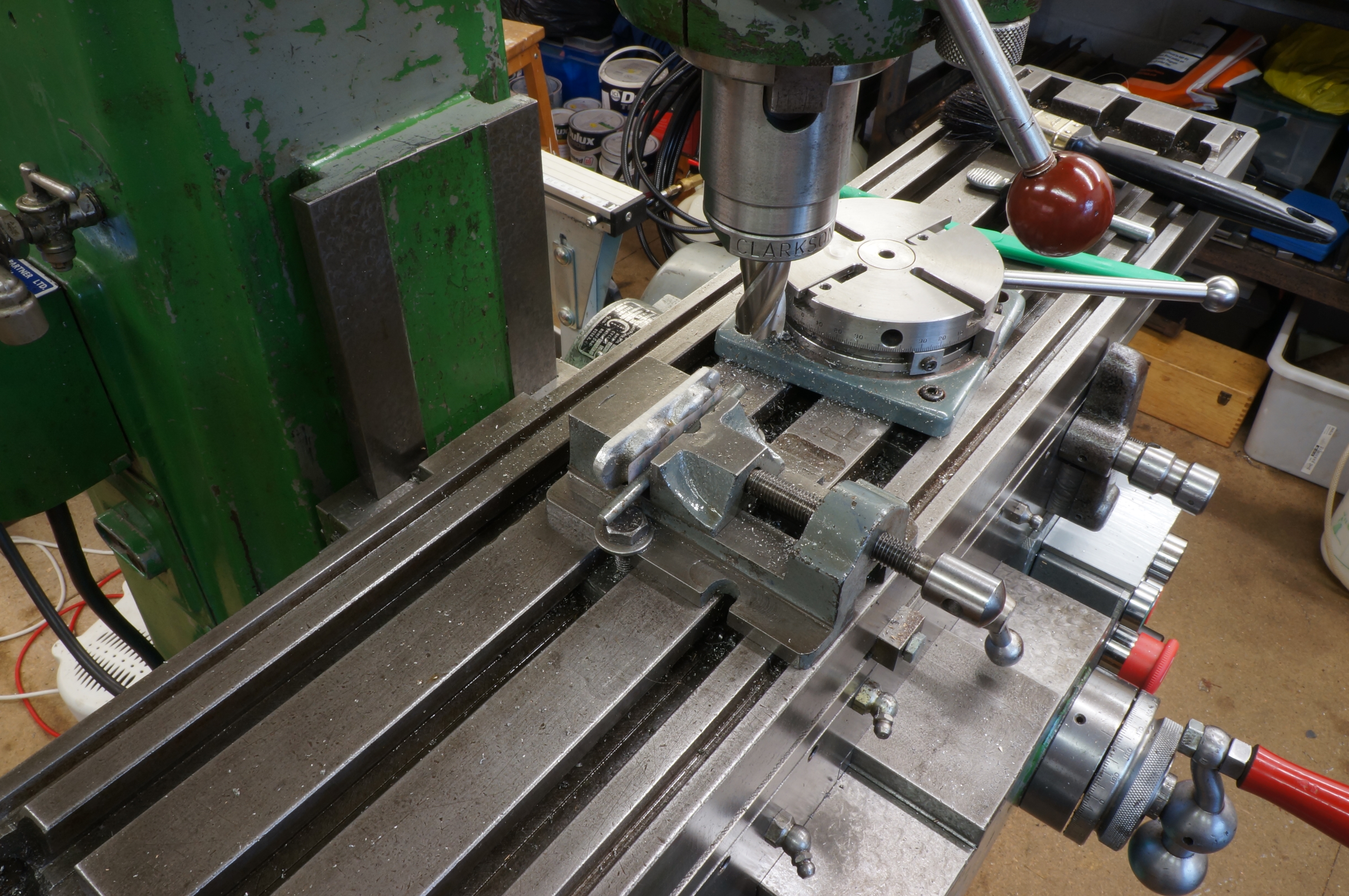
Continuing to tool up for milling the inlet tracts in the inlet manifold, I made a 3⁄16″ diameter centre locating pin for the rotary table, and drilled and tapped the jig plate. The tapped holes are for mounting the manifold on the plate, and there are two 3⁄16″ holes to fit over the locating pin, positioned at the centres of the inlet tract arcs.
The milling went well, with the jig justifying itself in making virtually fool-proof an otherwise extremely difficult set-up. The external shape of the casting meant that the cavity needed to be 11⁄32″ deep in the middle to fully uncover the inlet hole from the carb, but no more than 5⁄16″ at the ends to allow a safe thickness. I used a ¼″ ball-nose slot drill, and cut the left hand side first, using increments of 0.005″ in depth for every 15° of rotation of the rotary table. I found this looked too coarse, so I filled in the intermediate 7½°, 2½ thou, steps. The right hand side I cut with the smaller steps from the start, and it looks a bit neater. Even with the jig, this all still needed concentration.
The last job was to rub the face flatish (final lap later) on some 1200 grip paper to remove the small amount of epoxy projecting from the face. (5¼ hours)
.
2014-10-09 - Finishing
I worked on smoothing out the machining bumps in the inlet passage. The best tool I found was abrasive paper wrapped round a match stick. This will need more work to produce a nicely polished surface.
I hardened the 7⁄32″ filing buttons, finished a special bolt to fit tightly in the 2.8 mm bolt holes, and made a start on fettling the round the end lugs, finishing to the final overall length. (2¼ hours)
.
2014-10-18 - Finishing
I did a little more filing round the right hand end lug, and started on filing buttons to make filing templates for the carburettor flange and exhaust manifold end flanges. More of this work at the Exhaust Manifold. (2¼ hours)
2014-10-18 - Drilling the carburettor flange
After more work on the flange templates, I drilled the port and mounting holes in the carburettor flange, and milled a finishing cut of 0.003″ across the flange. Using a9⁄16″ end mill at 800 rpm, the finish could have been better.
2014-11-11 - Fettling
After finishing shaping the exhaust manifold earlier today, I had a little time to get back to the inlet manifold. (¾ hour)
2014-11-15 - More fettling
Today I was mostly working on concave shapes round bolt hole bosses, and on refining the shape of the inlet tract. (1¼ hour)
2014-11-21 - More fettling
I continued working round the right hand side, and in the concavity at the top centre. The right hand side is now almost done. (4½ hours)
2014-11-29 - More fettling
This morning I finished work on the inlet manifold. I think it looks a lot better than it did, and is ready to be bead blasted. (2 hours)
.
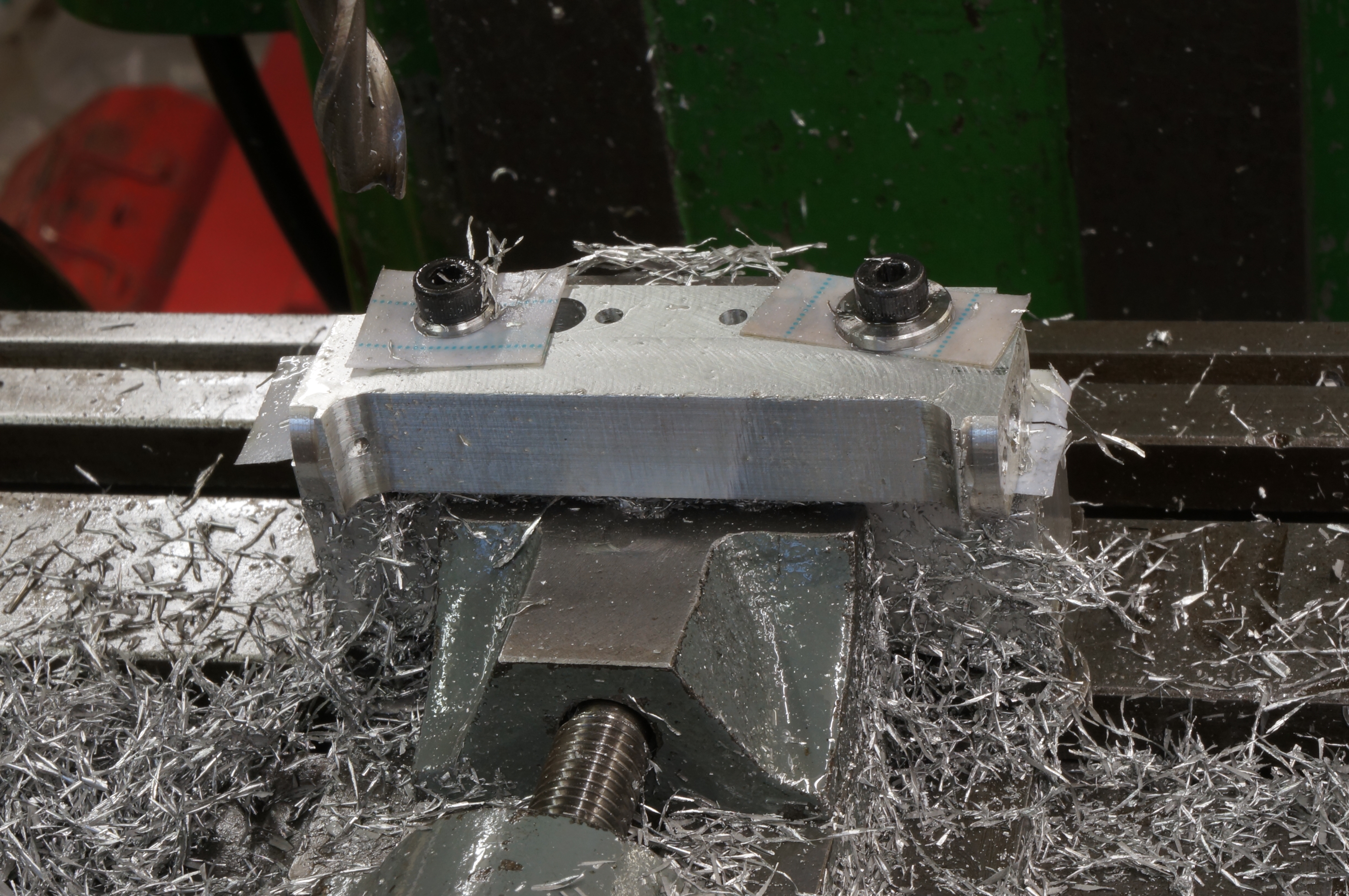
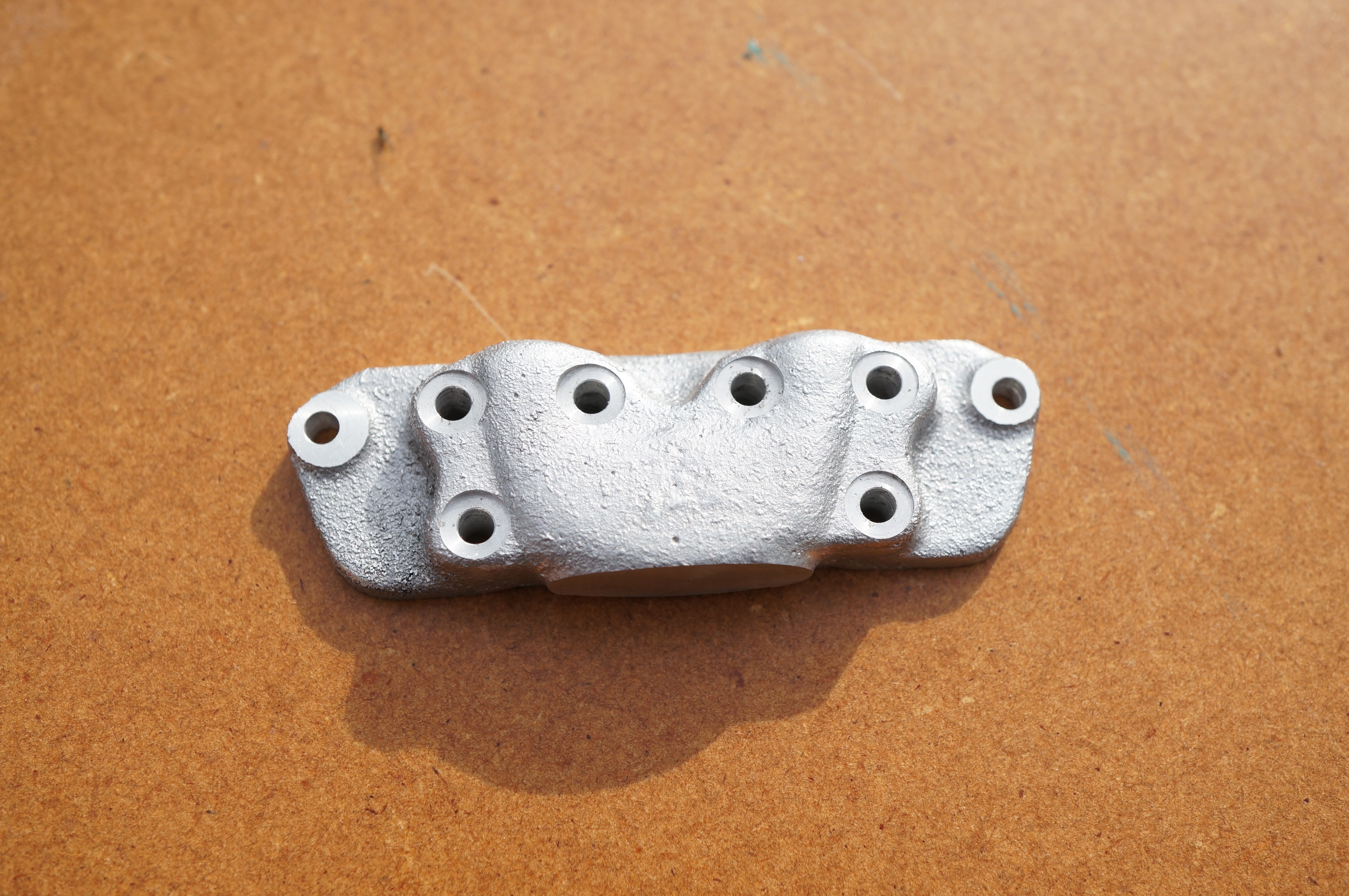
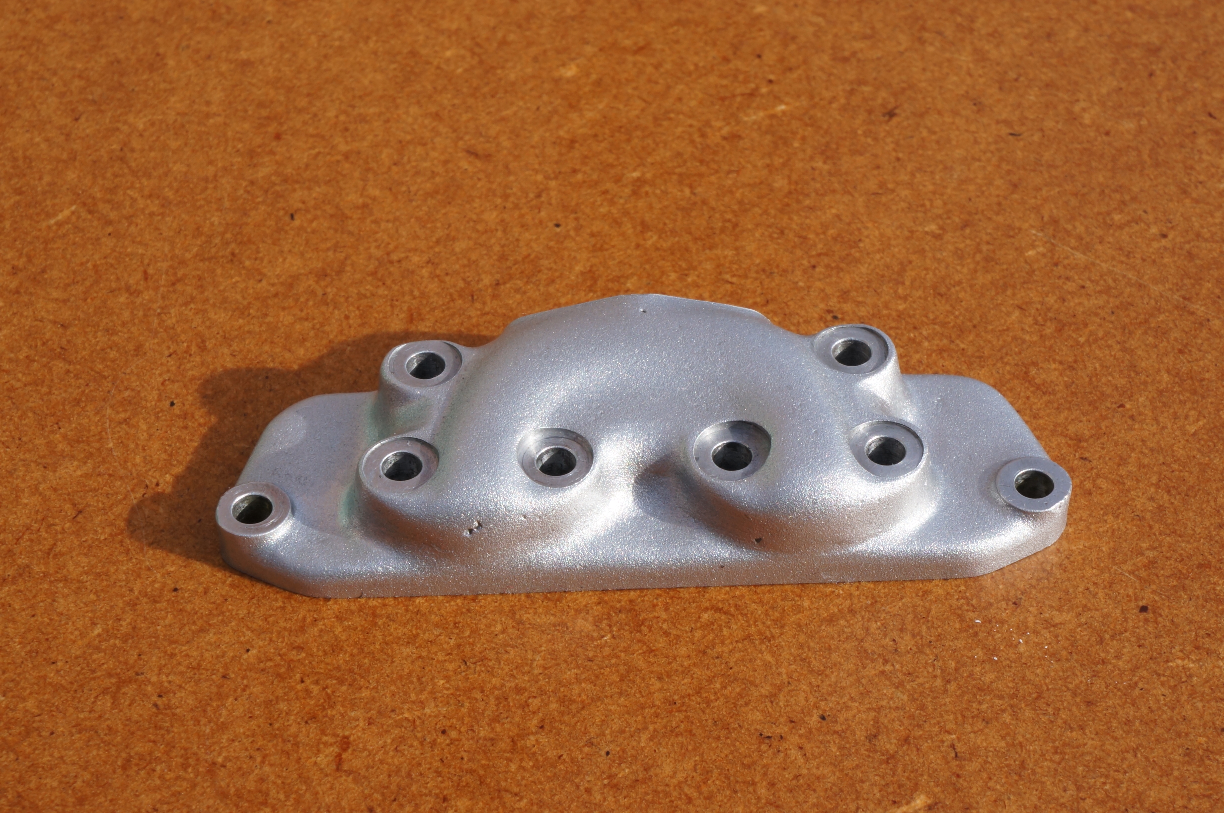
2015-01-24 – Bead blasting
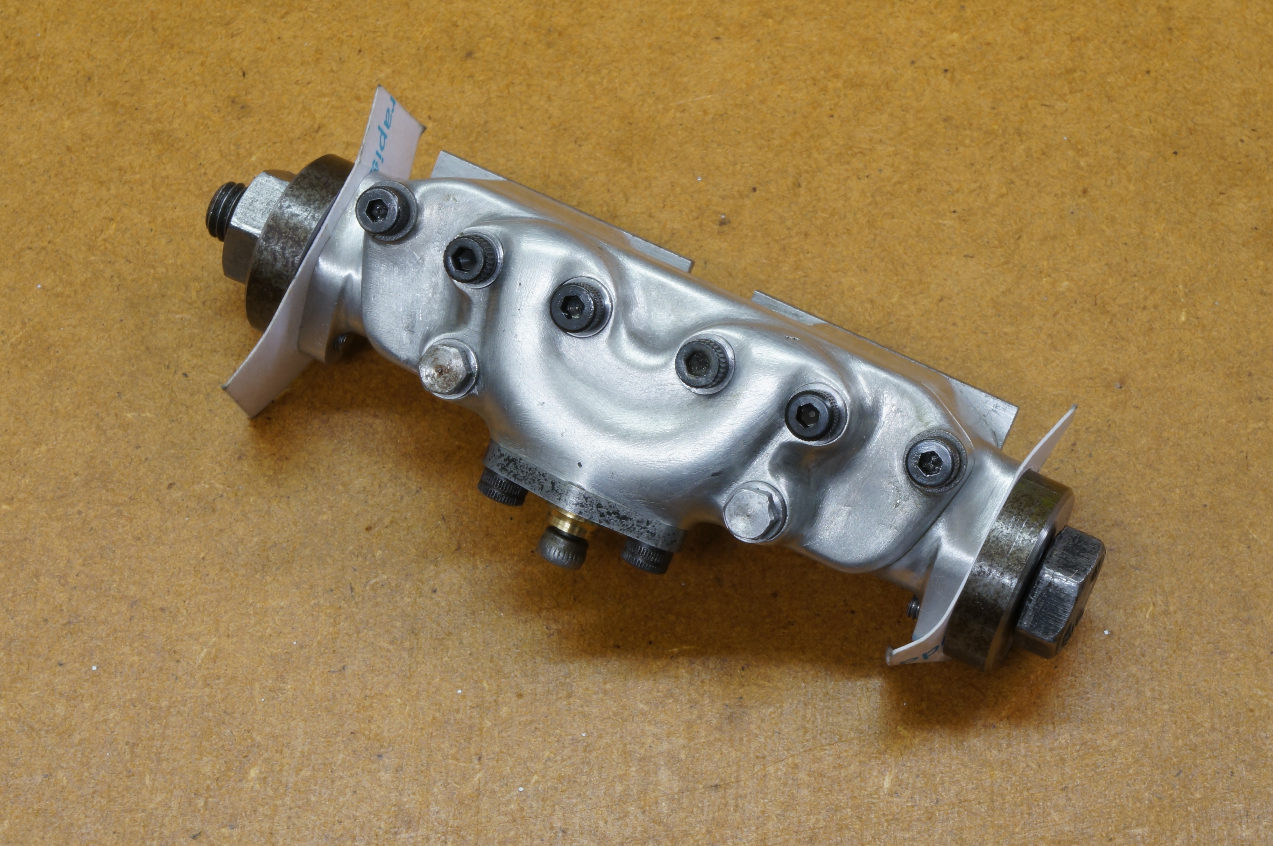
My new bead blasting cabinet arrived earlier this week. Time to have a go. First I made a pair of thick ¼″ washers to cover the end flanges.
Then I ground a 0.025″ wide parting tool and used it to make ten special, temporary 6BA washers 0.215′ diameter to cover the spot-faces, trying out different thicknesses intended for the final assembly washers, and, having decided, one with a chamfer to see how that would look.
I cut screwdriver slots in a couple of left-over experimental 6BA studs and used these to fill the tapped through holes in the bottom lugs of the end flanges.
The template for the carburettor mounting flange can be used, but new plates were need to cover the port faces, as the one hardened template was lacking a hole for the central bolt (necessary to protect the spotface on the inlet manifold). New plates were cut from some 1.5mm thick mild steel strip, and milled to a suitable rectangle. After drilling the holes I filed the plates one one side almost to the template profile to ensure the relief area at the back of the manifold would be properly exposed to the blast.
The photo above shows everything bolted up ready for blasting, which of course only took a few minutes. I dusted it off, stripped it all down an wiped it over. It looks good. The exhaust manifold is a bit bright, but that may tone down with time and grime. (5¼ hours)
.