
Valve Guides
I think the drawing for this part is probably wrong, both in the series and on the sheets. The Seagull shares numerous design features and dimensions with the earlier Seal, particularly in the timing and valve arrangements. However, whereas in the Seal's General Arrangement drawing, the valve liners are shown as leaving a 1⁄16″ deep pocket below to allow more room for the valve spring, the Seagull GA does not. The Seagull, moreover, has a 3⁄16″ longer valve stem, so the recess is not necessary. I suspect Westbury forgot the difference and copied the Seal drawing, especially as the drawing appeared, with an apology, one article later than the description. Anyhow, I am making mine with the 5⁄16″ diameter 7⁄16″ long instead of 3⁄8″ thereby increasing the overall length to 13⁄16″. The stem will have a short 3⁄16″ diameter register for the top end of the valve spring, and the rest will be a bit smaller to allow clearance.
I also concluded that, by very slightly increasing the valve stem diameter from 3⁄32″ to 2.5 mm, I could use a 7 BA thread on the valve stem, which has 30% greater core area than the 8 BA originally specified.
A piece of bearing bronze about 0.55″ diameter is provided for the valve seats, guides, cages or liners. The first choice material suggested by Westbury is iron, and while it might have been possible to find enough metal for guides in the cast iron bar provided for the cylinder liners it would have been difficult and risky and clearly not what was intended in the kit.
2014-08-10 - Roughing out and boring
Given the difficulty I have experienced with drilled holes in bronze wandering off centreline, I was a bit worried about making these parts, so a preliminary job was to sharpen my 2.1, 2.3 & 2.4 mm drills using the DAG Brown pattern Small Drill Sharpener that I made earlier in the year. This device puts a 4-facet grind on these little drills. I also sharpened a zero-rake, universal, turn-and-face tool. I have a brand-new 2.5 mm reamer, bought for the job. I decided to follow Westbury's guidance on the best sequence for making these parts.
I also checked the diameters of the seatings in the cylinders. These were reamed 5⁄16″ and proved to be just the right fit for Loctite on a piece that was dead on nominal size.
The first operation was to rough out the external diameters, leaving them 5 to 10 thou oversize with a similar amount to come off the shoulder faces. I parted each blank, remembering to leave enough for facing while still leaving the overall length at least 10 thou over for final the facing cut over the assembled cylinder, liner and valve seats.
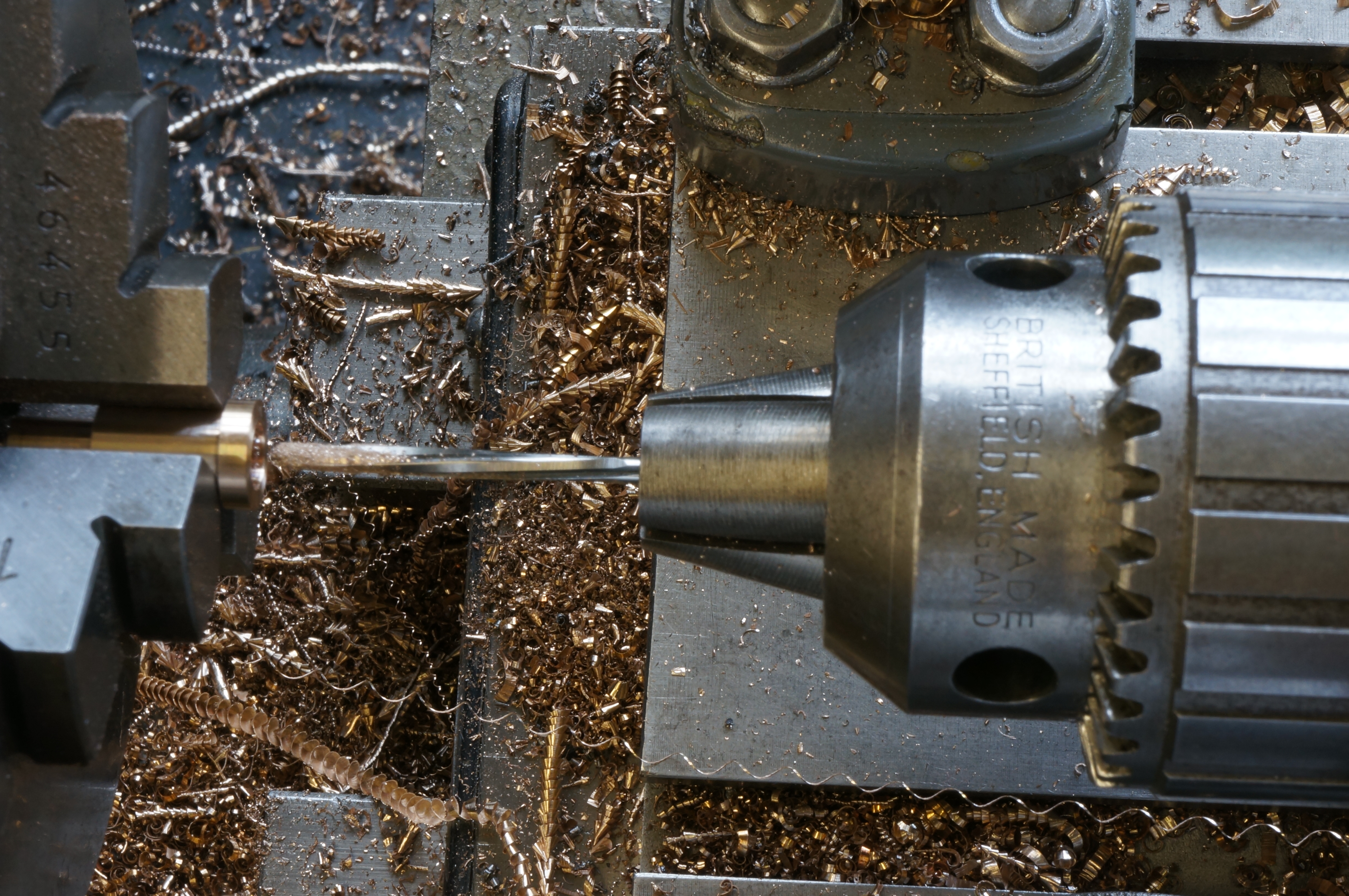
For the second operation I adjusted the Grip-tru chuck to hold the first piece running true, and then used the same chuck pinion for all the rest. They do not need to be dead on yet, as the exterior still has to befinished. With each part, once I had established the best sequence, I faced the flange a bit over size, centre-drilled and drilled 6mm to 5⁄16″ deep all at 750 rpm, then at 2000 rpm, centred again with a No 1 centre-drill, drilled 2.1, 2.3 & 2.4mm in sequence, and dropped back to 750 rpm to put the 2.5mm reamer through. The initial 2.1mm drill tended to grab, but taking it by pecks, blowing out the swarf and allowing a bit of time for the job to cool between pecks seemed to improve matters. After the first one I sharpened the 6 mm drill too, as it threw up a burr.

Finally I put a ¼″ ball-nose slot-drill down to just less than finished depth to form a radius in the bottom of the passage. This will be finished by putting the same cutter through the cylinder ports after assembly.
I took each part out to measure the overall length, and then took a final facing cut to leave each part 0.825″ long. This allows 12½ thou for final facing.
I was very pleased to find that I seem to have managed to drill all the valve guide holes straight, and the reamer has left them with a very good finish. (4 hours)
2014-08-16 - Finishing the outside
I turned, filed and polished a bit of mild steel to fit the valve guide bores, and ran them over it in the lathe for a few seconds with plenty of oil to knock of the highest spots off the bores and to get a diameter for the valve stems. It turns out they want to be 0.0985″, or a small gnat's over 2.5mm.
Next I made an extended 7 BA nut, and then a stub mandrel. As the valves will need the same treatment in due course, I experimented a bit with my 7 BA die, with not very satisfactory results, as it seems to leave 1⁄8″ or more of partial thread. I have a set of one each size BA chasers, but they are ex-die-head and would need adapting for single tool chasing.
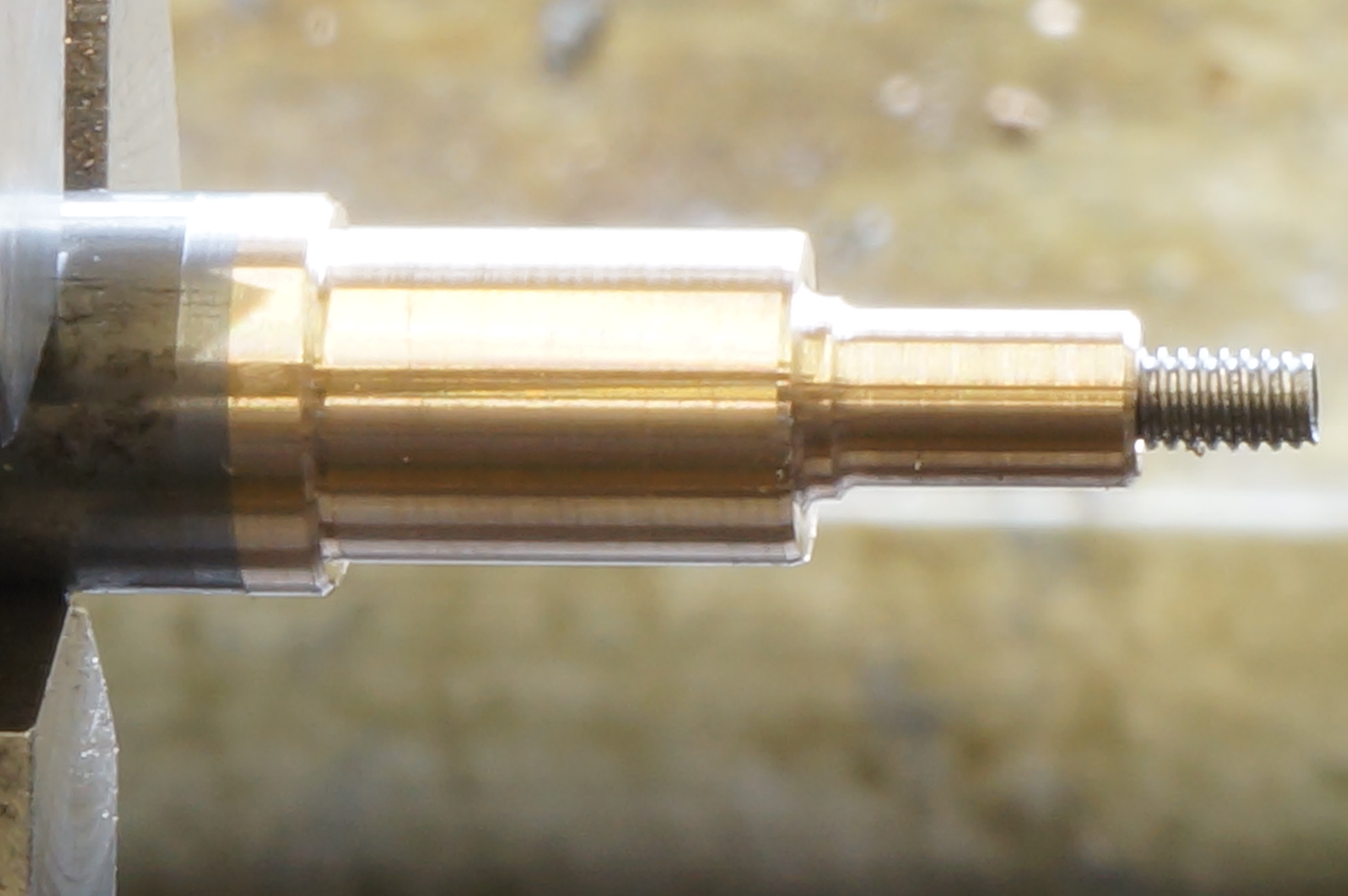
With the mandrel completed, and a sharp corner tool ground, I could finish the outsides of the guides. At a seating diameter of 0.3127″ and with the top flange at 0.374″ they would fit nicely into the cylinders. A 3⁄16″ register for the spring, with a bit of a radius in the root for strength, allowed the spring to seat nicely. In bit of a hurry to finish the last one, I forgot to reduce the top flange to thickness and had to put it back. Normally, I like a radius at the tip of a turning tool, but I found that with this bronze, a sharp pointed knife tool would easy remove a fraction of a thou, and a second cut at the same setting could be used for a final shave. The bottom end and flange, I chamfered at 45°, while I gave the seating diameter a 10° chamfer, hoping to avoid scraping the Loctite out of the hole on assembly.
The valve guides are now finished as far as I can take them before being fixed in to the cylinders. (5¾ hours)