
Centre Bearing Cap
The drawing for this part is incorrectly dimensioned. As drawn it is well proportioned, being 1″ wide with holes pitched at ¾″, but the dimensions do not tally, being 1⁄8″ greater in each case.
2010-04-16 - Milling and drilling
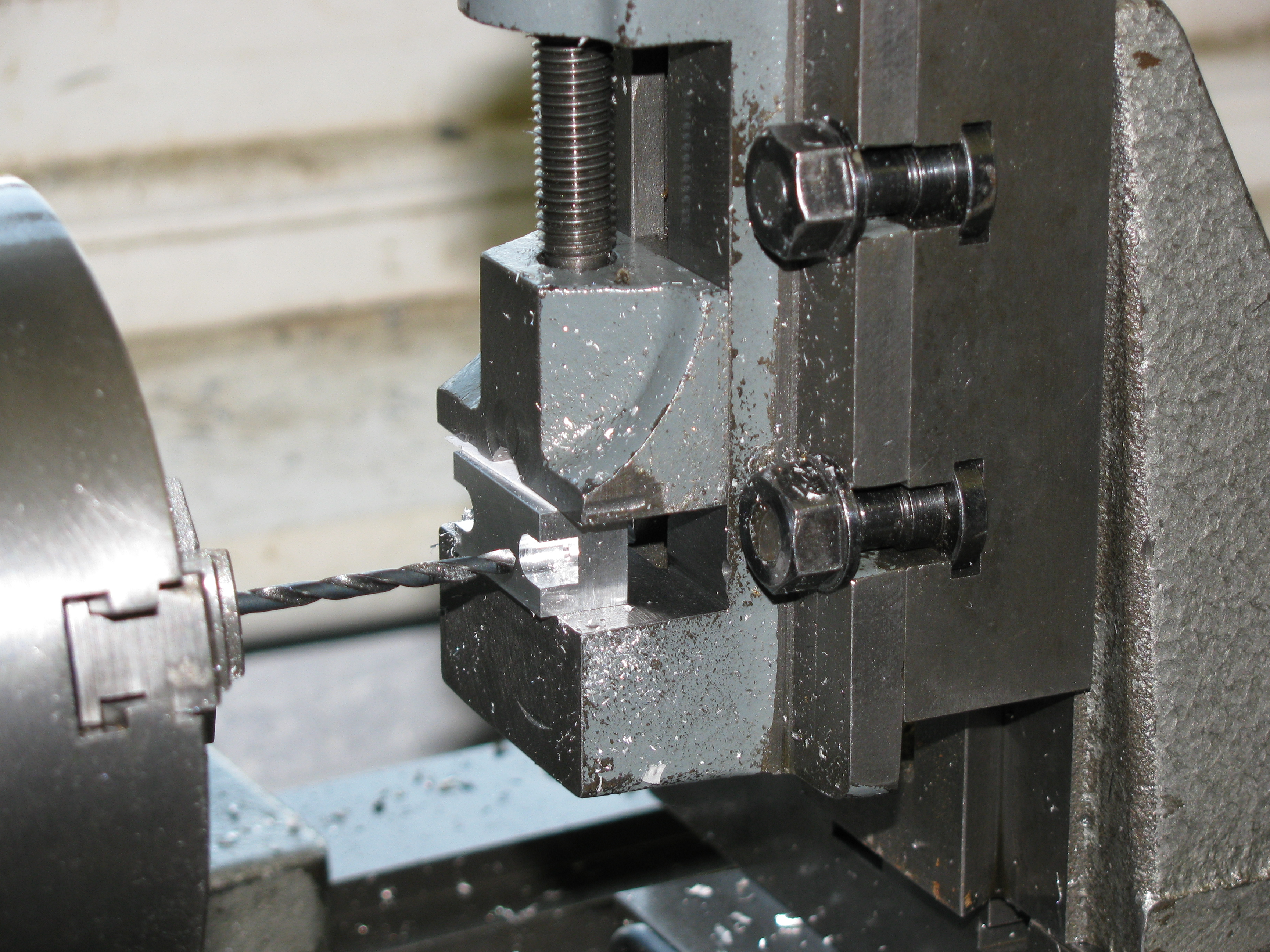
No casting is supplied for this part, and while it could be made from some of the ¾″ dural bar supplied, I used a piece sawn from a stock slab and roughed out using the 4-jaw chuck. I milled it to finished size (actually oversize on width, for boring and facing in situ), milled the pockets for the cap-head screws, drilled the holes, and milled angles on the shoulders. Although the holes were drilled 2.8mm, dead size for 6-BA, there is still some play on the bolts, which are a bit undersize. So I can drill accurately placed holes sometimes. Typically, just when I want a tight fit. I think rotating the bearing halves a little will provide a step location each side. I can try this before drilling for the anti-rotation peg. (2½ hrs)
Boring was done in place on the crankcase.
Crankshaft Bearings
The original drawing for the timing end bush is wrong. The flange should be thinner at 3⁄32″, like the other bushes. The only deviation from original design is to rotate the split line of the centre bearing by 15°, so that the flanges of the bearing bush halves locate the bearing cap. The geometry at this angle is about the limit that will assemble without extra clearance.
I am not used to making little bearings with the quality of fit and finish that I want for these, so I will need to do a bit of experimenting and take extra care.
2010-09-04 - Experiments
I am starting to think about how to get an accurate smooth bore in the these bearings, and to do a few experiments. Using a brass offcut, I tried boring and reaming with my 3⁄8″ reamer. Reaming was done with an allowance of 4 thou on diameter, at 300 rpm. The resulting hole is something like 0.0006″ over size, which gives more clearance on the crankshaft than I really want. I would like to start with something closer to ¼ thou over 3⁄8″. On the other hand, the finish was really quite nice.
In fitting this bearing to the shaft (I tried both ends for the sake of comparison) I tried making a radius to match the crankshaft. It looks good, but I did not take the huge amount of care that would be needed to get a fit all round the curve. I think it will be worth a try though. A plain chamfer seems like a cop-out here, when I took care to get good radii on the shaft. During fitting, I discovered that there is a slight step in the shaft, about 5 thou on diameter, extending 3⁄64″ from the crank web faces at each end. I am not sure whether to try to remove them, or to fit the bearings to them.
I have already made up a 3⁄8″ lap for another job, and although it is too long for these bearings, I decided to try it out. Obviously the hole was already oversize, so I was looking for finish, roundness and parallelism rather than exact size. It seemed reasonably easy get a better job than by boring, but fine valve grinding paste (silicon carbide) is too harsh. (2 hrs)
2010-09-10 - More thinking and planning
The boring I did before reaming did not seem to give a very accurate or smooth hole, so I need to ream, scrape, or lap. I could take a slip stone to the reamer to make it cut a bit smaller. The centre bearing, being split, is accessible for scraping, and while it might be possible to get at the back end bearing, the front one is far too long. I do not want to take any risk of getting lapping compound embedded in the bronze, and therefore need a softer abrasive. Previous discussion on modeleng.list has brought up Timesaver but this is expensive. Rouge, tripoli, or crocus powder might be suitable, but I don't know where to get them. The combined resources of household and workshop offer Astonish, Brasso, 3/0 pumice powder, and rottenstone. Some more experimentation is called for.
In the meantime, some progress can be made. As I intend to finish the bores in situ in the housings, at the same setting as turning the register diameters, the bushes for both ends can be prepared all bar the finish bores. The centre bearing can also be made, complete apart from fitting to the shaft diameter, which will need to wait until the ends are finished to provide alignment. The bar supplied is not large enough to get both halves of the centre bearing out of one length. As this seems a bit wasteful I will use a piece of larger bearing bronze from stock.
2010-09-11 - Preparing the bushes
I stupidly wasted a bit of metal by turning the shoulder of timing end bush to the overall length, and turned it to a few tenths over size before even starting the bore. Fortunately boring, to 0.02″ under size for finishing in position in the housing, resulted in a slight expansion, so I was able to skim the outside later. It was parted off the bar and a similar job done on the longer bush for the flywheel end. Boring this one resulted in some high-frequency chatter, so the bore is a little uneven, varying by up to 0.001″.
As these bushes will be Loctited into their respective bearing housings before boring in situ, the business of finish machining the bearing surfaces will be dealt with in the sections for the timing and flywheel end housings.
Fitting the bearings to the crankshaft will then be dealt with here.
The Heath-Robinson set-up for slitting the centre bearing did not work well as the partially split bar kept on closing-up on the slitting-saw and causing it to unscrew. (Always run a saw like this so that the arbor will unscrew if the saw jams. This frequently saves both job and cutter.) I eventually got to depth by shimming the saw on opposite sides to induce a wobble. The job tries to stop the saw wobbling, so the saw kerf tapers. This means that, after sawing the loose half off by hand, the mating half-bearing faces had to be milled to ensure the joint plane was truly axial. (4¼ hrs)
2010-09-21 - Trial bores
I am far from satisfied that I know how to get the bearing bores as good as I would like I did some experiments. First, I took a little rub off my 3⁄8″ reamer with an external lap. Using a short offcut of bearing bronze, I drilled and bored it to 0.0015″ undersize and tried the doctored reamer, lubricated with RTD and running at 300 rpm. This produced an amazing polish on the bore, but, after a second pass, the diameter varied from -0.0008″ at the tightest to -0.0004″ at the easiest. Clearly, reaming has mostly burnished the hole. I stoned the cutting edges very lightly to get them cutting better. Trying it again, dry, it left a spiral finish to a bore that is actually quite smooth and pretty parallel, 3 tenths over 3⁄8″. This runs nicely on the crankshaft, with the tiniest amount of shake detectable at the timing end, and feeling the slight roundness error at the inboard part of the flywheel end. Now I need to know how the reamer will work on a piece that it has not already burnished.
Taking a 3⁄8″ length of the supplied bearing bar, I bored this to -0.0008″ at the mouth, and a shade tighter in other parts, bigger than I intended. Again, reaming this dry, it squealed like hell. I gave it 2 passes of the reamer, but I should have measured it after the first pass. The result was +0.0008″ at the mouth and +0.0002″ at the back end.
I am still not really happy to go ahead. I bored anther piece to 2½ thou under size. Tool spring is a bit of a problem. Reaming, with a bit of RTD still squeals a bit, but it cut quite nicely. There were some very fine chatter marks on the bore, which was again bell-mouthed from +0.0007″ at the front to +0.0002″ at the back. I scraped this one until parallel and about 0.0009″ over nominal, removing all the machining marks at the smaller end.
From these trials I concluded that reaming is not going to give the results I want. I start work on making a new copper lap. (4 hrs)
2010-09-22 - Trial lapping
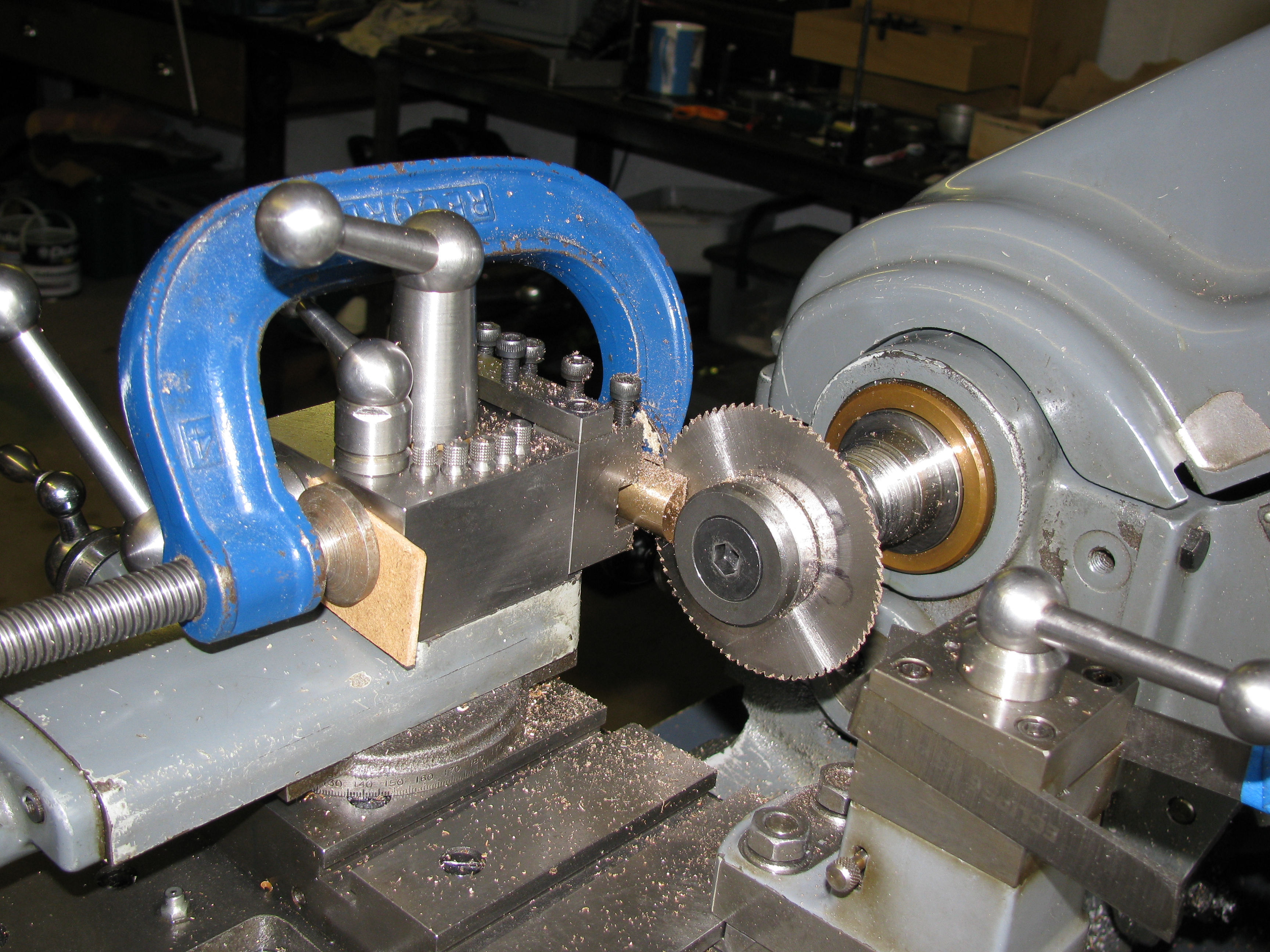
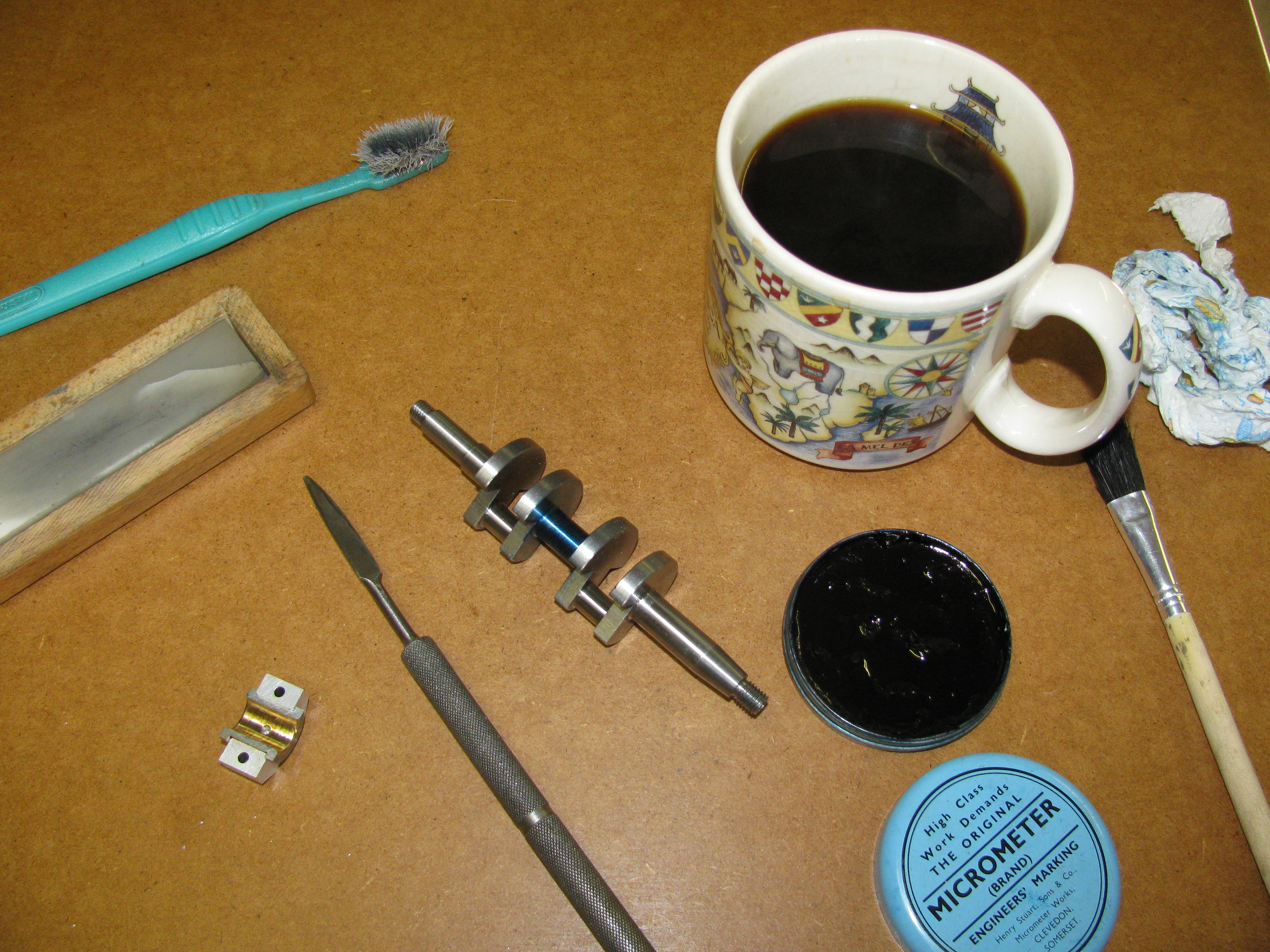
After completing the lap, I tried it on the first brass test piece. Trying Brasso as a lapping compound, I enlarged it by a thou to +0.0013″ in a minute or so, giving a smooth, round, parallel bore. The second piece went from a range of +0.0002″/ +0.0008″ to +0.0008″ / +0.0010″ in a few seconds of rather too stiff operation. The lap is still cutting only at its inner end and will need adjustment to get the desired barrel shape. It seems that the way to work is to hold the thing with the hole in the hand and move it over the rotating cylindrical part, whether lapping internally or externally. What is surprising is the speed with which Brasso will cut.
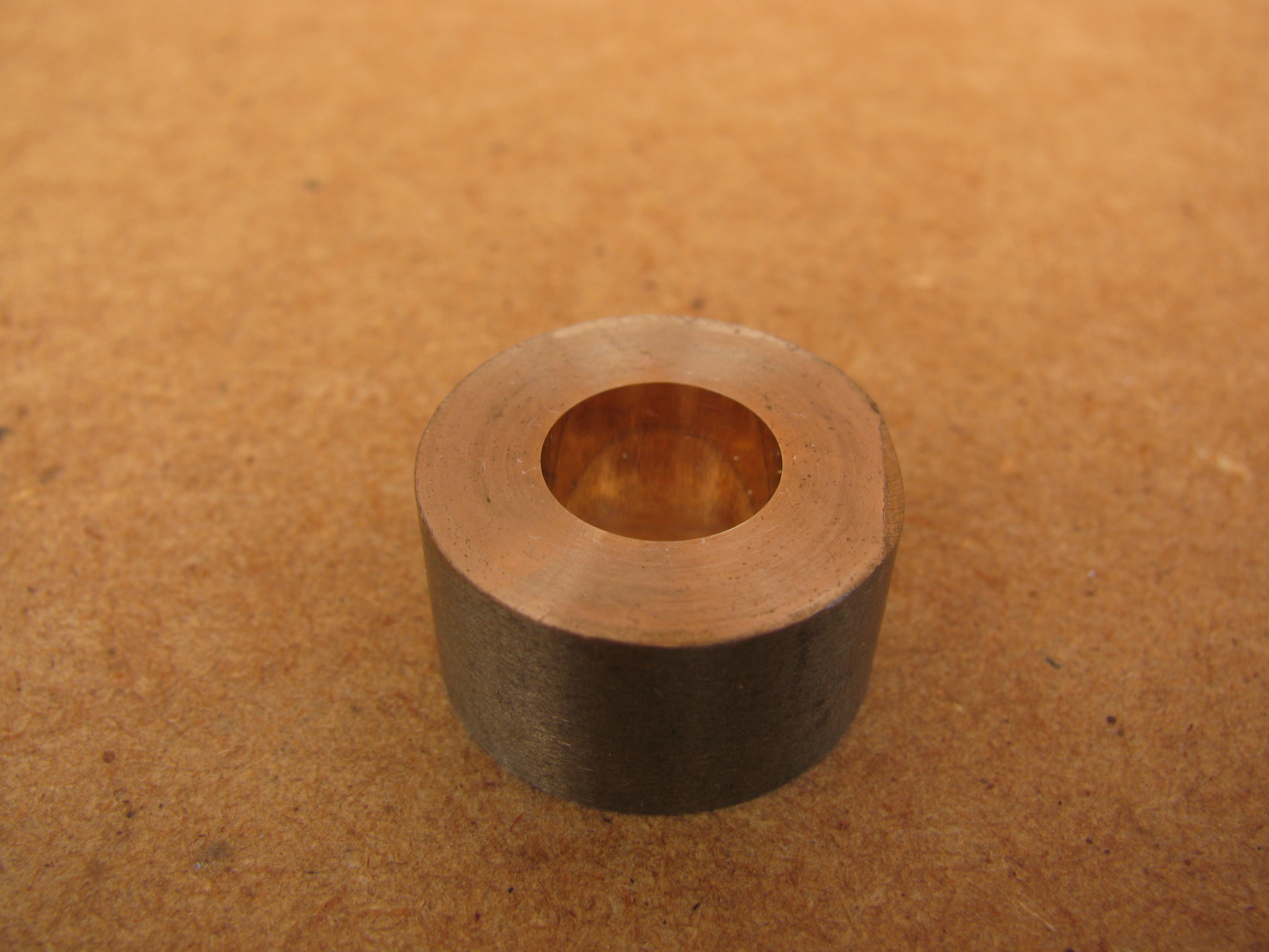
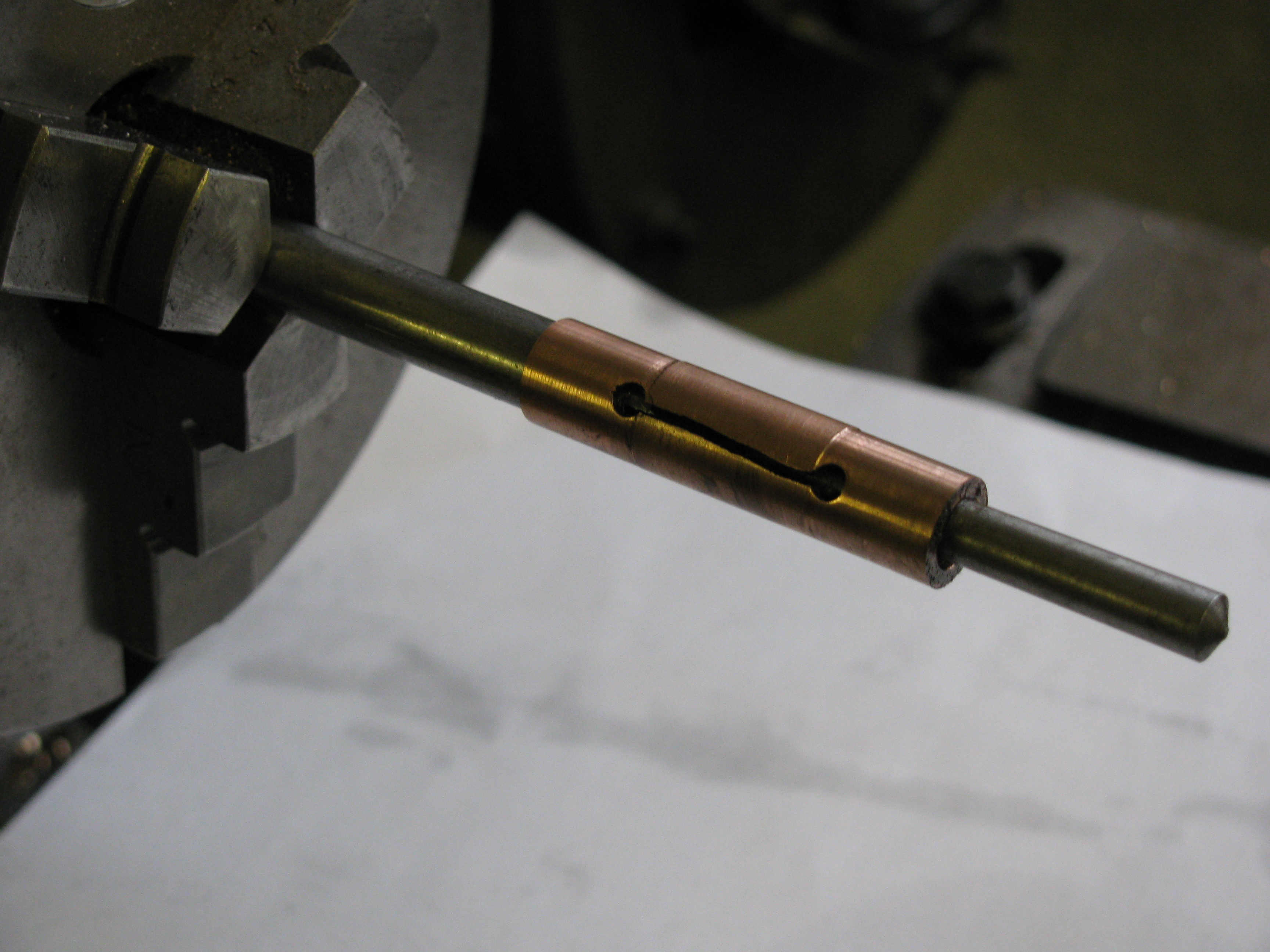
In the photo, the steel rod holding the lap has a shoulder that extends half way through the copper, is split at the end and drilled quite deeply with a parallel hole. The lap is expanded in the middle by tapping the end of the taper-pin a bit deeper into the hole in the rod. The copper is just some annealed thick walled tube, it is driven by friction. (about 1 ½ hrs)
2010-11-07 - Lapping for real
In trying to re-profile the lap, I managed to chew up the copper, so had to make another. With this running in the lathe at about 200 rpm, and still using Brasso, I worked on both bearings a bit at a time on each, until the shorter timing end bearing just goes onto the shaft. (2 hrs)
2010-11-08 - First fitting
After another half-hour's lapping today both bearings fit on the crankshaft, but not right up to the shoulders. After a careful wash with hot water and detergent, blueing up shows distinct ridges at the inner ends of the shaft journals. I used a collet chuck to hold the shaft by the flywheel end, and with the re-sharpened root radius tool between the chuck and the crank-web, and in bottom back-gear, I took a tiny shave off the blued-up shaft, almost into the root radius. The blue showed that the cut did not go all the way round the shaft, but I already knew it is a slightly out of round there. The bearing would then fit all the way on, albeit with a slight tight spot. The timing end of the shaft was given the same treatment. This cut more evenly all round and needed a shade more taking off. After a bit of scraping on the bearing's shoulder radius this one went on too.
After washing everything again, I tried an assembly. Although the bearings fit and turn individually, with the crankcase and bearing housings assembled, the crankshaft will not turn. With the sump added, it turns, but stiffly. After loosening the timing end a 2 thou feeler will go between it and the crankcase, so we obviously have an end-float deficit. I lapped 2 thou off the thrust face of the timing end bearing, but as the assembly still locked up I took 2 rubs of 1 thou off the flywheel end too. Now it turns but is still very stiff. The lapped thrust faces are not showing any signs of contact, and a 2 thou feeler will go in between the bearing and crank-web. Evidently the bearings are not going right home. After a bit more scraping the radii, everything was free enough to try turning the crankshaft with a small cordless drill-driver turning a spare nut on the shaft. After less than a minute of this, the shaft can be turned by gripping the nut with the fingers. (4¾ hrs)
2010-11-13 - More fitting, and more on the Centre Bearing
Dismantling again showed signs of bedding in, with bronze in the oil, particularly at the flywheel end, but no scoring. The shaft shows a very slight amount of pick-up at the front root radius. The flywheel end bush shows slight burnishing at the top outside and the bottom inside, suggesting a slight downward tilt.
Even now, neither bearing goes right up to the shoulder. I blued up and scraped the radii again on the both bearings until I had contact on the thrust face. Because I had evidently lapped the faces slightly out of square, they were only touching over a quarter to a half of the face. On reasssembly the crankshaft had not freed up much, but now, irritatingly, had about 4 thou end float. It would have been better if I had not lapped the faces at all. I should have had more faith in my own work. Fortunately, the centre bearing has not been made yet, and that can be used to locate the crankshaft axially with greater precision. Running it again with the drill, it begins to turn much more freely.
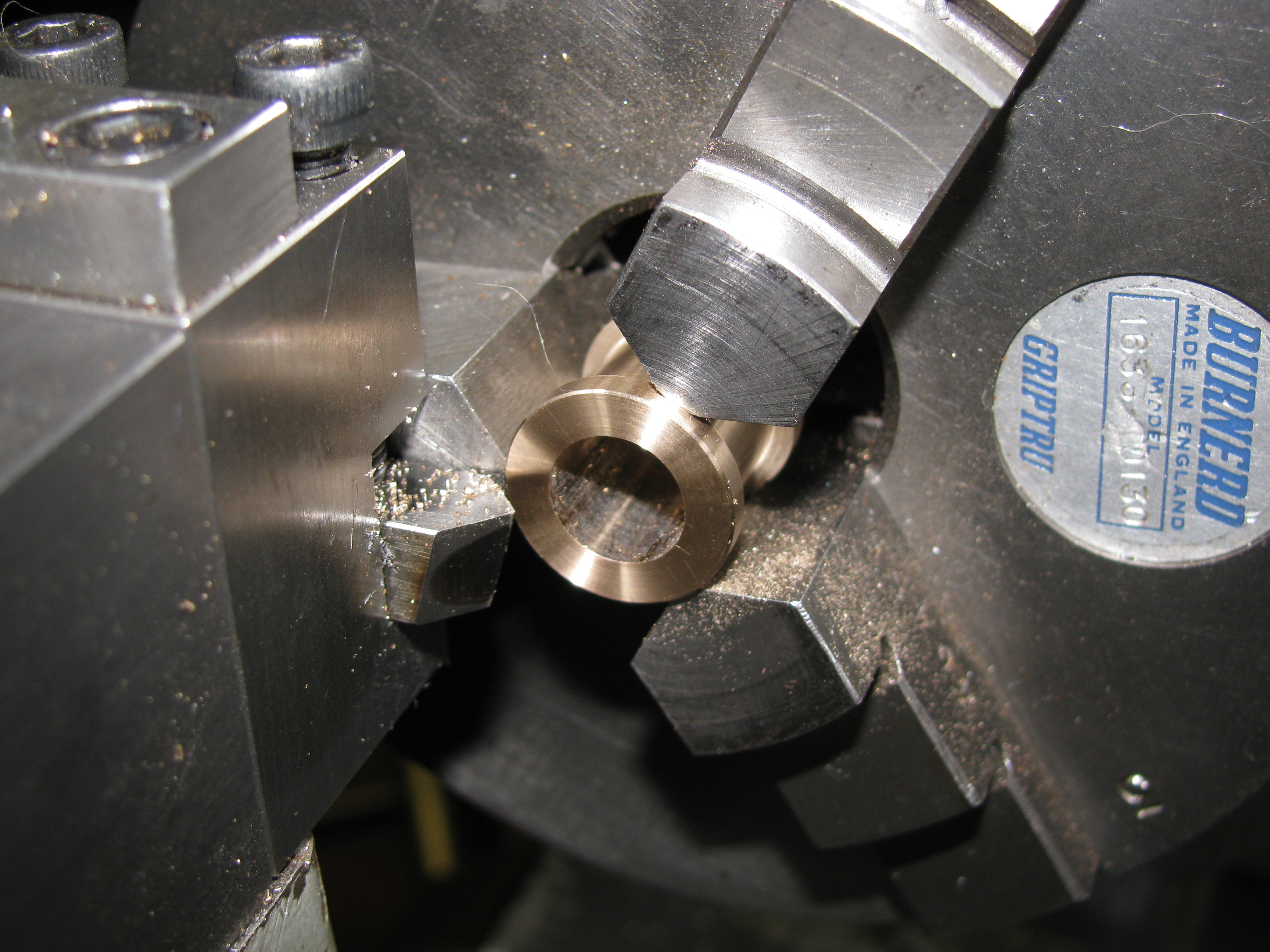
Checking the crankshaft with gauge slips, the centre bearing should start out at exactly 5⁄8″ long. With the sump off, I used a bit of gauge plate and feelers to find the end clearances between crank-webs and centre bearing housing. With the crankshaft against the front bearing there is 94½ thou at the front, and 96 at the timing end when drawn the other way. Equal 3⁄32″ flanges on the bearing, as per drawing, should be just the ticket. The bearing housing in the crankcase measures 0.4382″ over the faces while the bearing cap is 0.4388″. I lapped one side of the cap to match the crankcase, so that it could be used as a gauge for the bearing. The final measurement needed for the centre bearing was the bore. The centre journal of the shaft is 0.3733″ diameter.
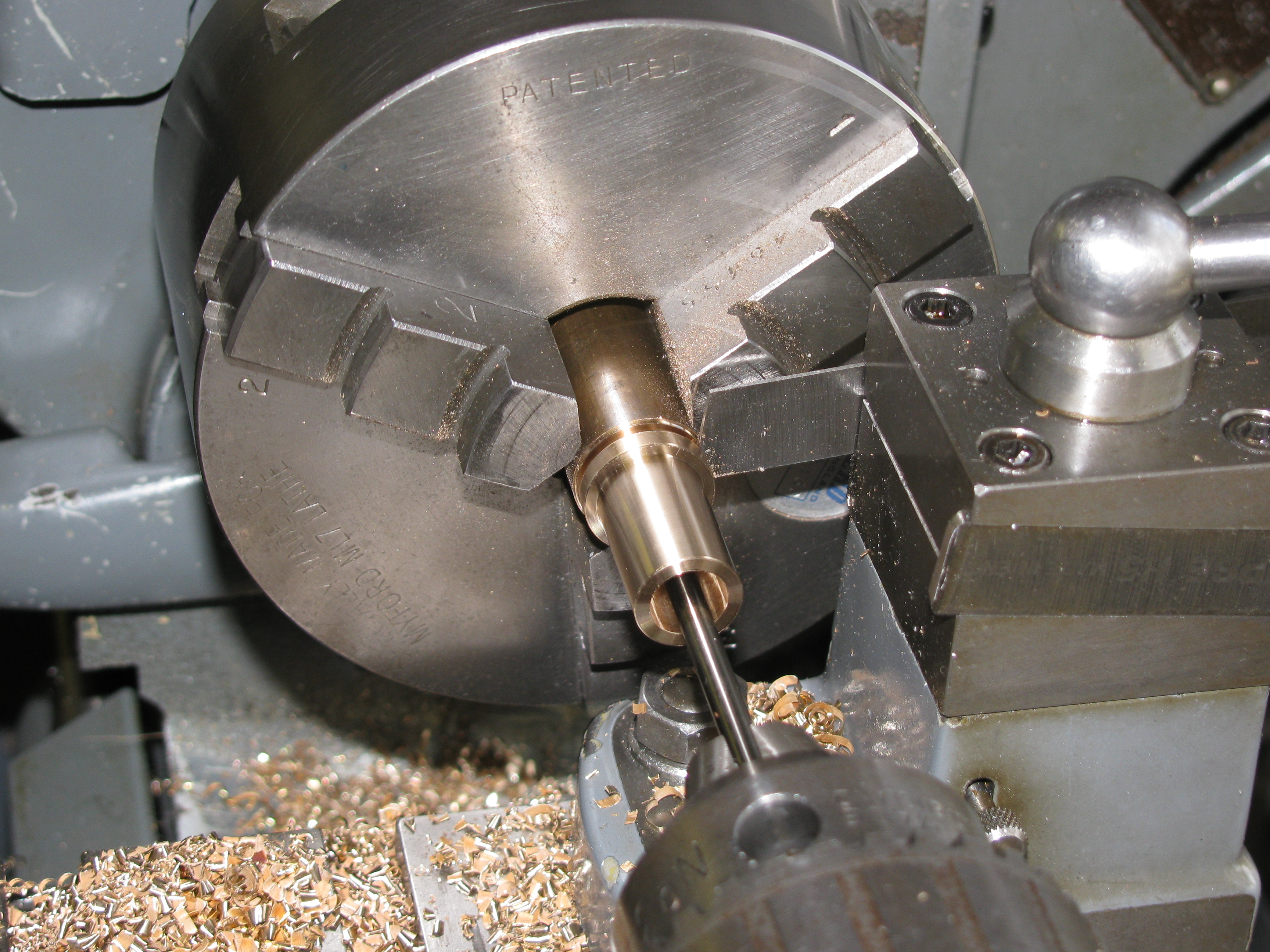
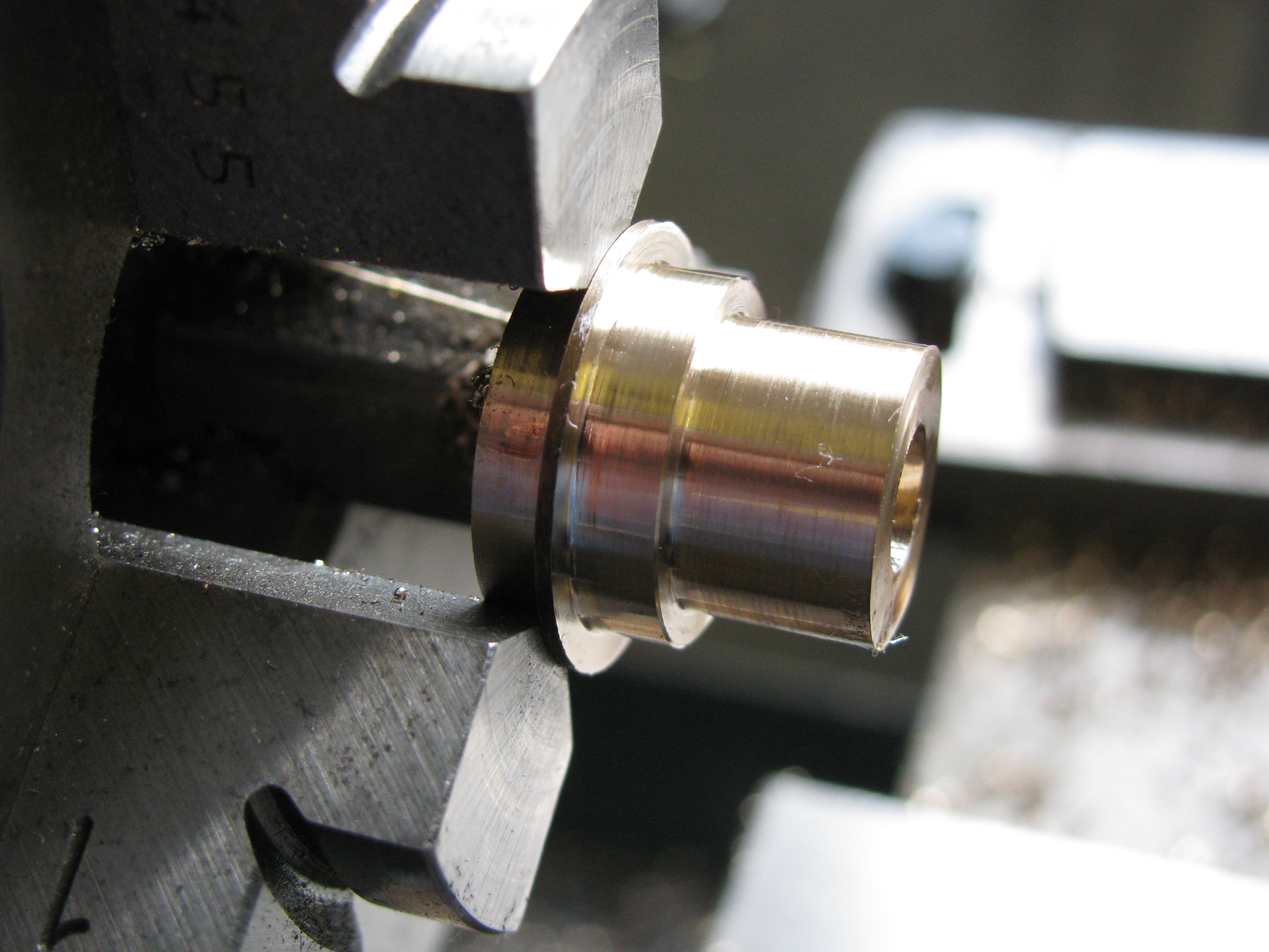
It did not take much to get the joint faces of the bearing halves to blue up nicely. It seemed quite difficult to get the faces tinned all over, and when sweating them together there was a tendency for the small piece to float out of place. After facing off I needed a strong light to be able to see the split line to get that truly on centre. I took a finish facing cut, turned the outside to 5⁄8″ diameter, centre drilled and drilled out to 8.75 mm. Working on the ½″ seating diameter, it was quite difficult to measure the width of the front flange as there was no room for a micrometer, and barely enough for calipers. I was happy with a measurement of 0.0945″, or there about. I nearly overdid the length of the seating. Luckily, it came out to 0.04384″, measured with slips, without needing an expected final cut. The bearing cap was a good snug fit between the flanges. I had to do a bit of fiddly shaving to get the seating parallel. Initially the outer end was 0.0015″ oversize. I may have used the topslide without checking it was set dead square. A little careful use of the carriage handwheel, and minute amounts of cut, got it parallel and 0.5002″ diameter. Phew!
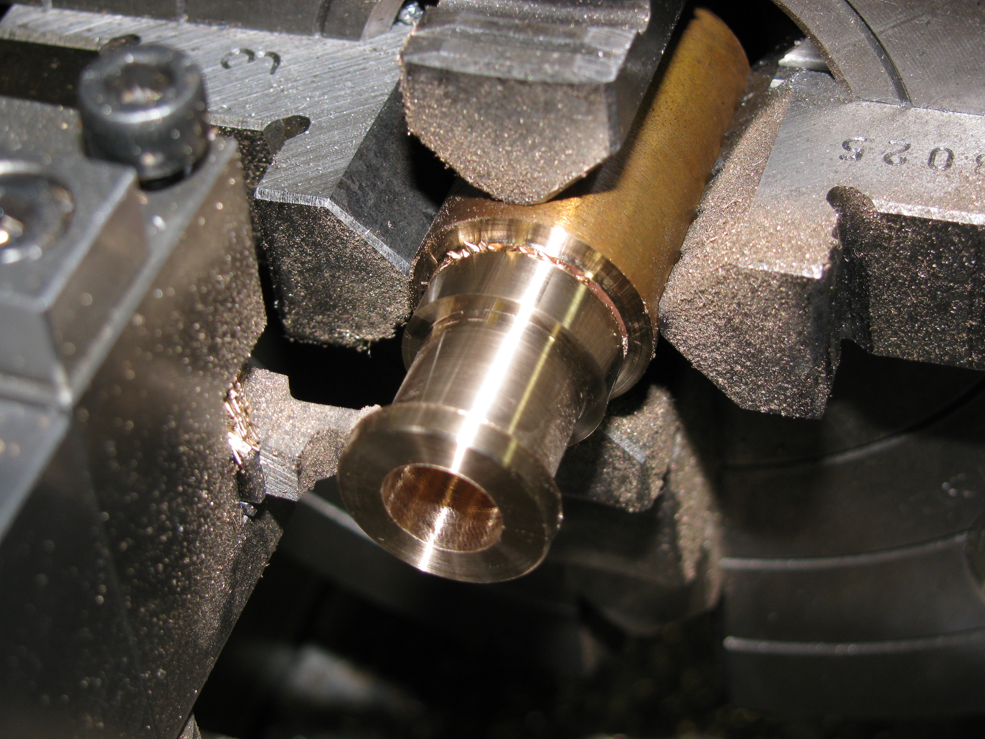
The photo shows the small gap, with an as-yet ragged edge, between the bearing bar stock and the back of the soldered half. (6¾ hrs)
2010-11-14 - Centre Bearing continued
After chamfering the inside corners of the flanges, I moved on to boring. With a freshly honed tool, the first cut was to about 15 thou undersize, but it seemed a bit out of round. As it was a cold day, the lathe was given 5 minutes at 1500 rpm to warm up a bit. Another 4 thou cut left the bore at -0.0053″ at the largest. A cut of ½ thou next. I found it very difficult to get a convincing reading in the bore. I have three different sets of small bore gauges from Starrett, Moore & Wright and Mitutoyo, and they all have a different feel. I am still finding bronze very difficult to bore well. With most other materials I can usually get a smooth, round, parallel and accurately sized hole, but not with this stuff. Polishing the tool very lightly and taking another half thou, the cut sounds more even. I measure it at -0.0035″. A second pass at the same setting seems to removes very little, so there is not much tool spring. The hole is also not signifficantly tapered, and if at all it small at the mouth. It now measures 0.0025″ undersize. A final cut of 1/4 thou leaves the bore -0.002″, as close as I a can measure. That will do. The rest will be scraped.

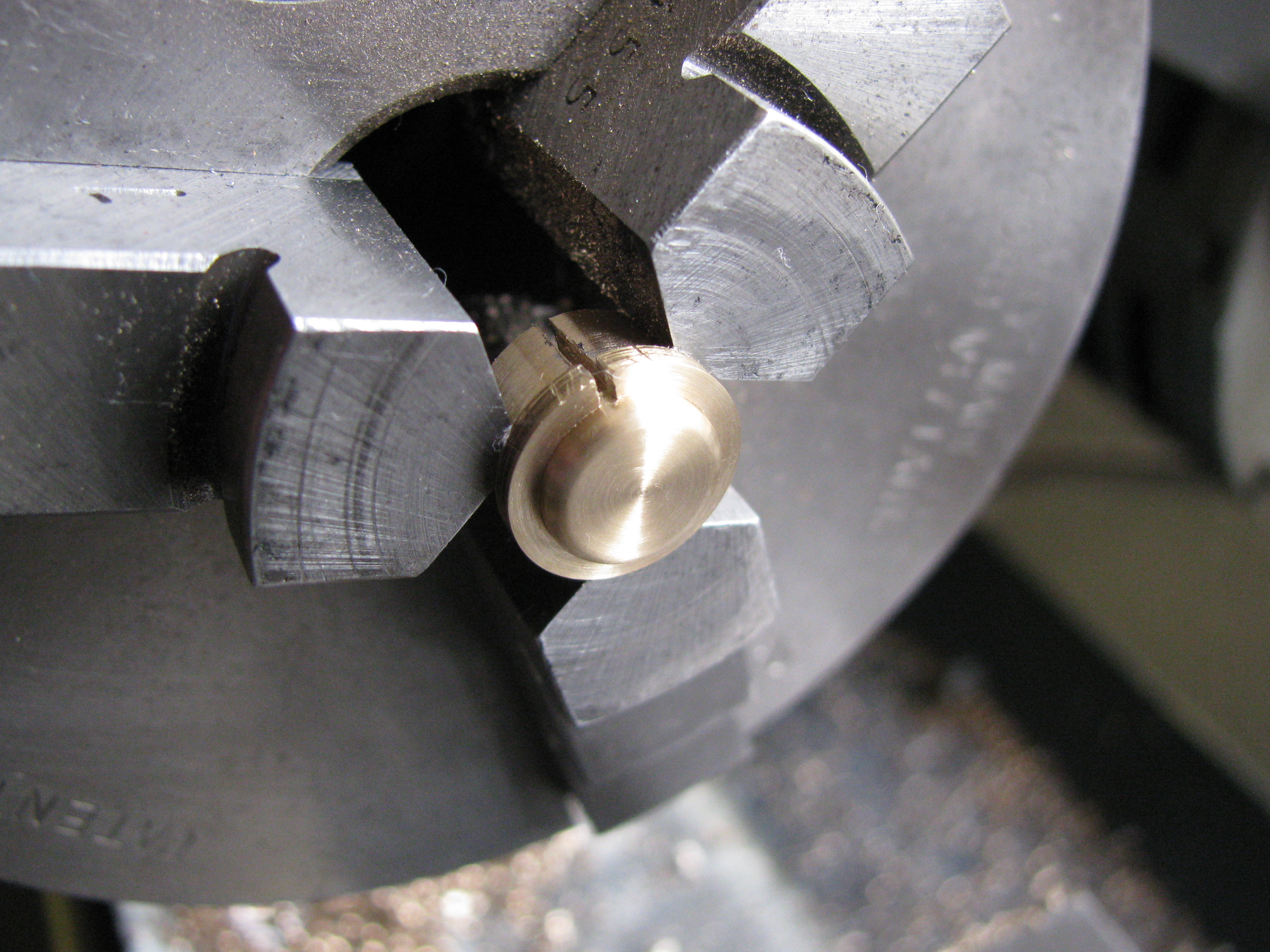
I machined a chamfer on the bore at 45° and then cut secondary chamfers at 22.5° & 67.5°, all to calculated depths, to prepare for scraping the radius. With my Indexing QC toolpost the angle settings are easy. After parting off, the bearing is a snug fit in the crankcase. Gripped gently in the three-jaw, I faced the other end to 5⁄8″ exactly, and repeated the chamfering operations. The fit between the crank webs was just right, no binding and no shake.
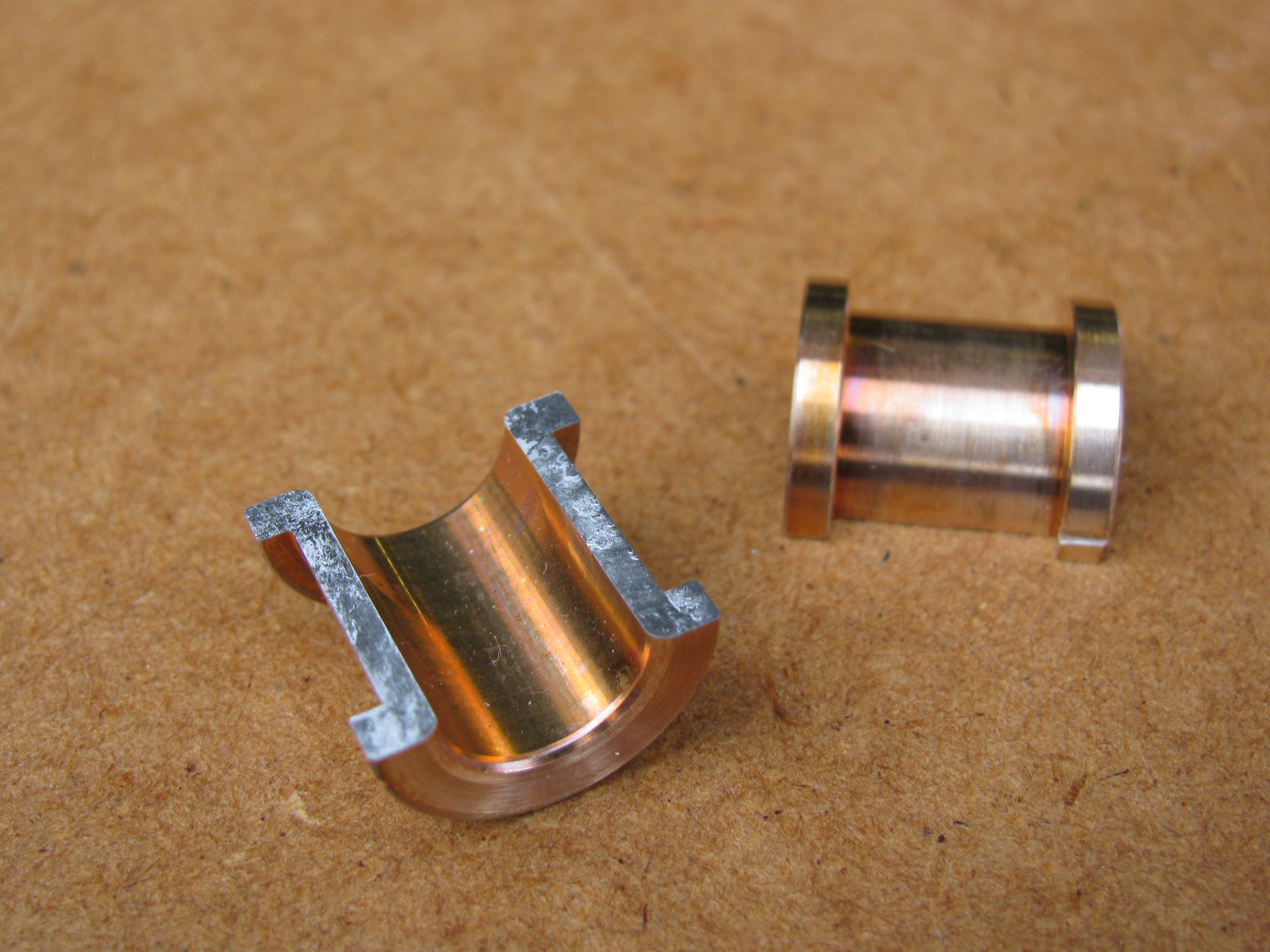
I filed a little notch adjacent to the split line on each half to mark the correct orientation. These notches go the same side as the punch marks on the cap and crankcase. After chamfering the outer corners, which I had forgotten to do, I melted the halves apart, and using a damp rag wiped as much solder off the joint as I could while the halves were still hot. When they had cooled down I lapped the faces very lightly just until flat. At this stage the shells do not meet round the crankshaft by about 45 thou. This is fine, as the radii are still far from finished.
I marked out and drilled a hole in the middle of the bearing cap and put a corresponding hole in the bottom bearing shell for an anti-rotation peg. A similar hole in the top half provides an oil way.
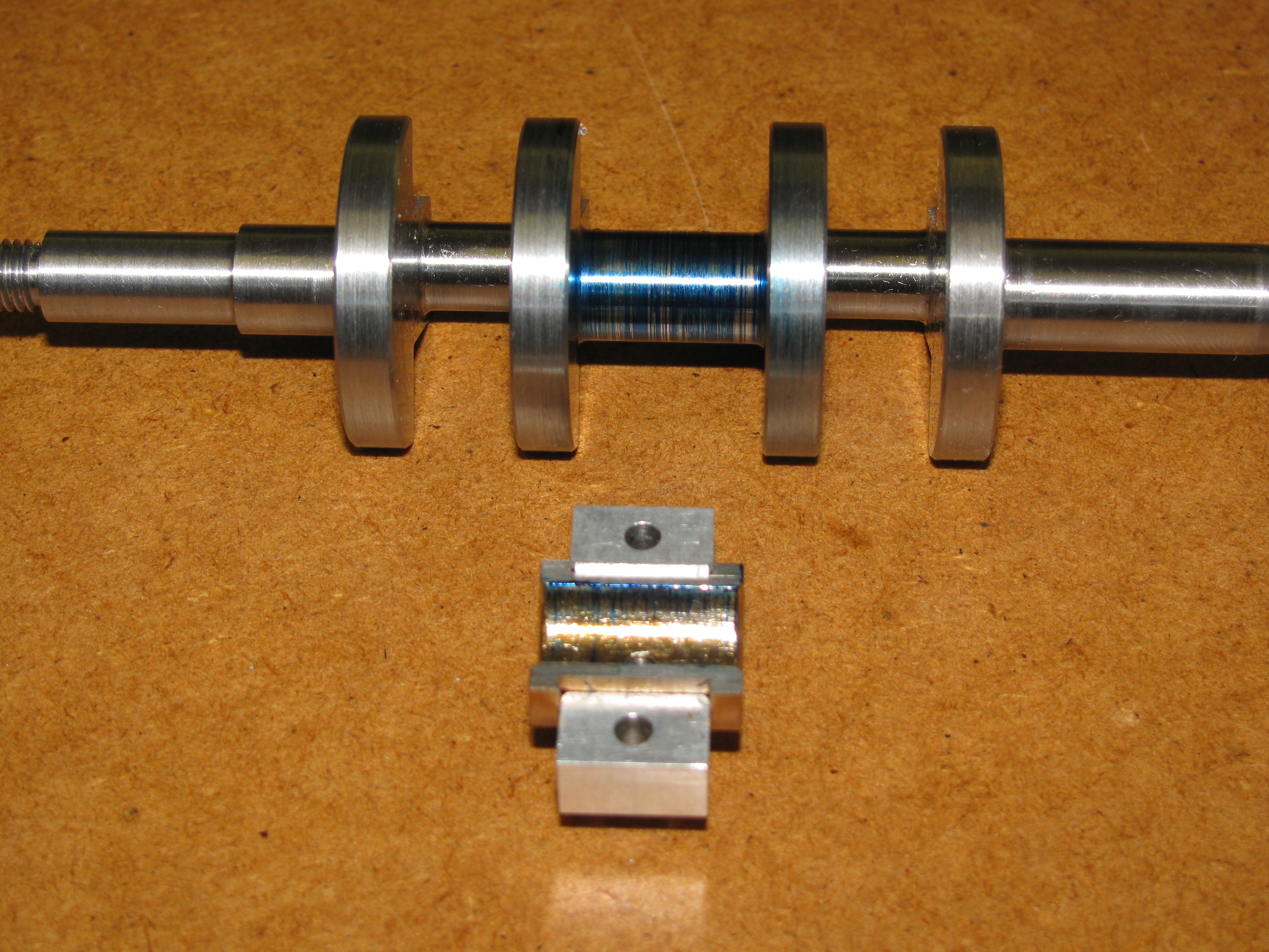
Once these holes are done I started fitting and scraping the bottom half shell. It is easier to a trial assembly with this half, as the crankshaft can be left in place in the outer bearings, with the sump off. It soon becomes clear that will not be an easy or quick job. The shell needs to be held in the bearing cap to manipulate it, otherwise it jams and is too stiff to turn on the shaft in the fingers. This is because it wedges on the root radii, at the corners only. After spending most of a long afternoon blueing up, trying in place, scraping the high spots, wiping clean and bluing again, the shell is able to turn without jamming, but is still only contacting along the edges. After some more work it blues up all over. I tried just the bottom half in place with the crankshaft held in the two outer bearings. The shaft will turn, but not if the bearing cap bolts are pulled up. This is as expected, because although the shell is a fit on the shaft, it is still too thick at the middle of the arc, where little scraping has been done. I briefly try bedding it with a little Brasso, which may be the way to finish the fitting job. (7½ hrs)
2010-11-15 - Scraping the top half
Working on this half I was more aggressive and probably went a little further than with the bottom half. It is noticeable how it starts to turn easily on the shaft once the edges are shaved back sufficiently. It sits down easily on the shaft and blues all over. Assembling the shaft in the centre bearing only, it will turn, but not with the cap tightened down, although it is not far off. With the end bearings in place it is tighter.
I removed the bottom half bearing and tried turning the assembly with the little drill-driver. I tried running it with a little Brasso in the top centre half, and it soon allowed an even film over the centre journal. On adding the bottom half, but not tightening it down, it is just possible to turn the shaft, but it is too tight for bedding in by running it. I tried a little more running, with the cap on, and with it off, using some Brasso in the bearing, but I soon decided it was a bit of a harsh way to treat it at this stage. I was particularly concerned that it might cause too much end-float to develop. Scraping seems to be the best bet. (4¼ hrs)
2010-11-20 - More scraping
Working first on the top half shell, I got this to a stiff but runable fit, with the end bearings in place. Then I took the top half out and worked on the bottom half until bolting it up increased the friction by about 50%.
With the end bearings removed and centre bearing cap tightened down it is now possible to detect a little play in the dry bearing. With some oil, not only does the play disappear, but the shaft will turn by itself under the influence of the balance weights. I really had not expected that at this stage. With the end bearings and sump added, and all tightened up and lubricated, the shaft can be turned by gripping the timing-gear seat between the fingers. This will do for now.
At this point the cold weather set it, and then I took a diversion for a tool-making session, so work on the Seagull stopped until March.
Camshaft Bearings
2010-11-07 - A pair of scrappers
As my ¼″ reamer is producing a nicely sized and finished hole, I tried drilling and reaming the bar for both of these in one go and without any boring (as I didn't have a suitable tool). Although I was careful to peck-drill and use 3 size steps, the hole wandered unacceptably. I tried boring it, but as the hole is long and narrow and the only suitable tool I have not very good, this was not very effective. The reamer had a distinct wobble on emerging. The scrap timing end bush can still be used to line up the timing end bearing housing and crankcase for drilling and tapping. (2 hrs)
2011-04-16 - Second attempt
The piece of bar I have left for these bearings is only just long enough to allow one chucking length, and a short one at that, so the bore will again have to be done in one go through both pieces. First I turned a step on the outside for chucking more securely and recessed the end so that my 11⁄8″ long 3⁄16″ boring tool would pass right through from the other end. I turned it round and faced, centred and drilled through 4.9 mm. The drilled hole has a bit of a wobble at the back end, but it is not bad. Roughing the outside, I stupidly put on a 30 thou cut, which fetched the job out of the chuck in short order. Fortunately, rechucking, using a tail centre as a guide, showed it was still fine. I had some trouble getting the outside diameters right, with tiny final cuts removing either nothing or too much, even after resharpening the tool. In fact, the fits I obtained are perfectly suitable for the intended Loctited assembly. After putting light chamfers on the corners, I bored out the hole to about 3½ thou under size without difficulty, and put a well-lubricated ¼″ reamer through in one pass at 300 rpm.
I have a piece of very smooth and very accurate ¼″ steel reclaimed years ago from a defunct VCR. This is a very nice running fit in the resulting bore. Using this bar in the tailstock chuck to support the end, I parted-off the timing-end bush, and faced the remaining piece to give the right length of shoulder for the flywheel-end bush, leaving it a little bit big for later adjustment of the camshaft end-float. Again, after lightly chamfering, I turned it round in the chuck and adjusted the Griptru to get the flange running true. I faced the flange to length, bored the recess for the cap, and put fine chamfers on to finish.
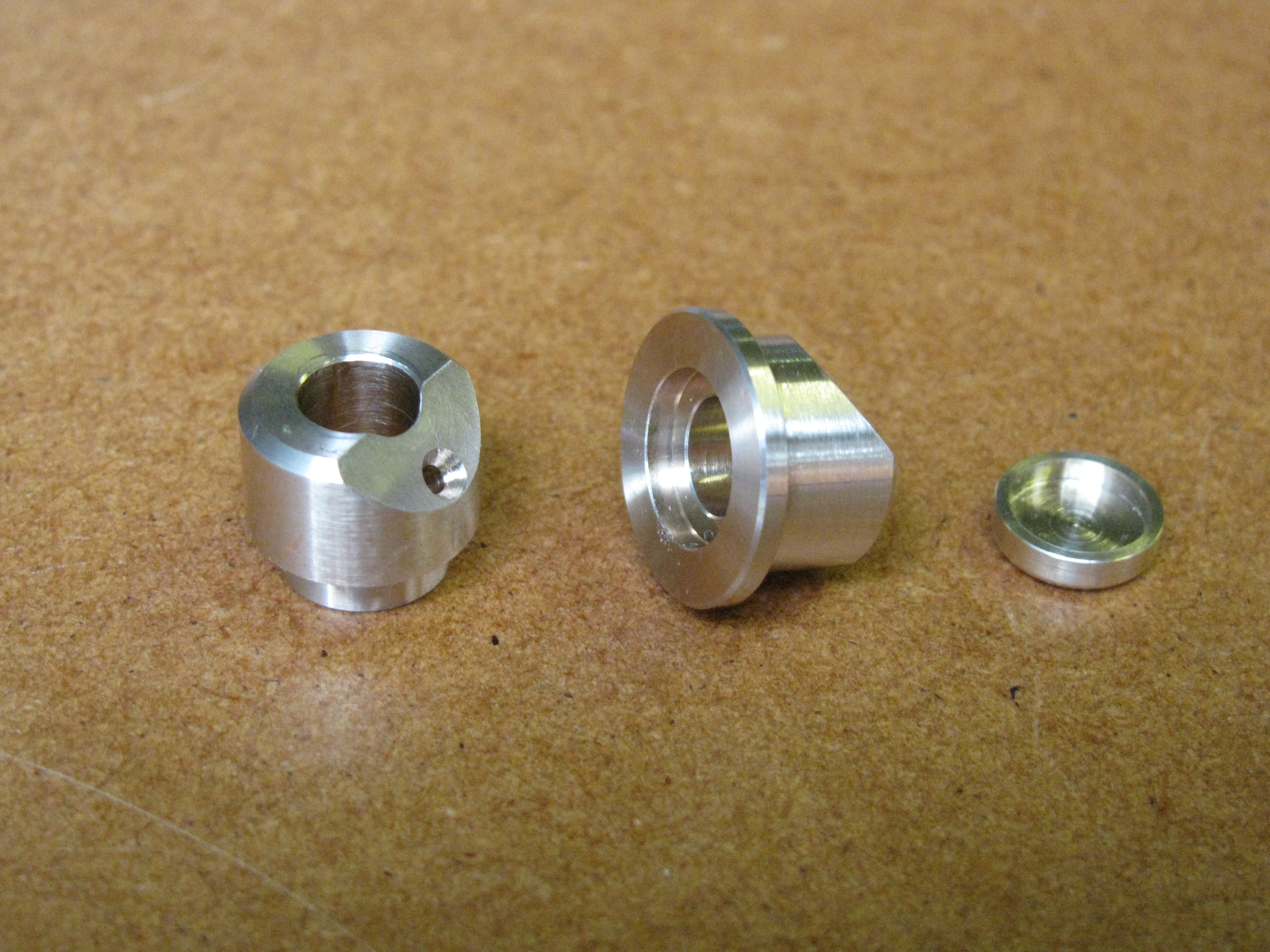
With the flywheel end bush out of the chuck I could finish the turning jobs on the timing end bush by facing it to length and chamfering. Next, I parted a bit of brass bar and turned a shoulder on it. Reversing it in the chuck I turned the OD of the cover cap, and bored out the shallow recess to about 5⁄16″ diameter. After parting the cap off, I drilled the remaining piece and counterbored to fit the cap. Marking this bush for the position of No.1 chuck jaw, I took it out and slit it. Using this cup to hold the cap I turned the outside to length, and chamfered, filed and polished the radius on the corner.
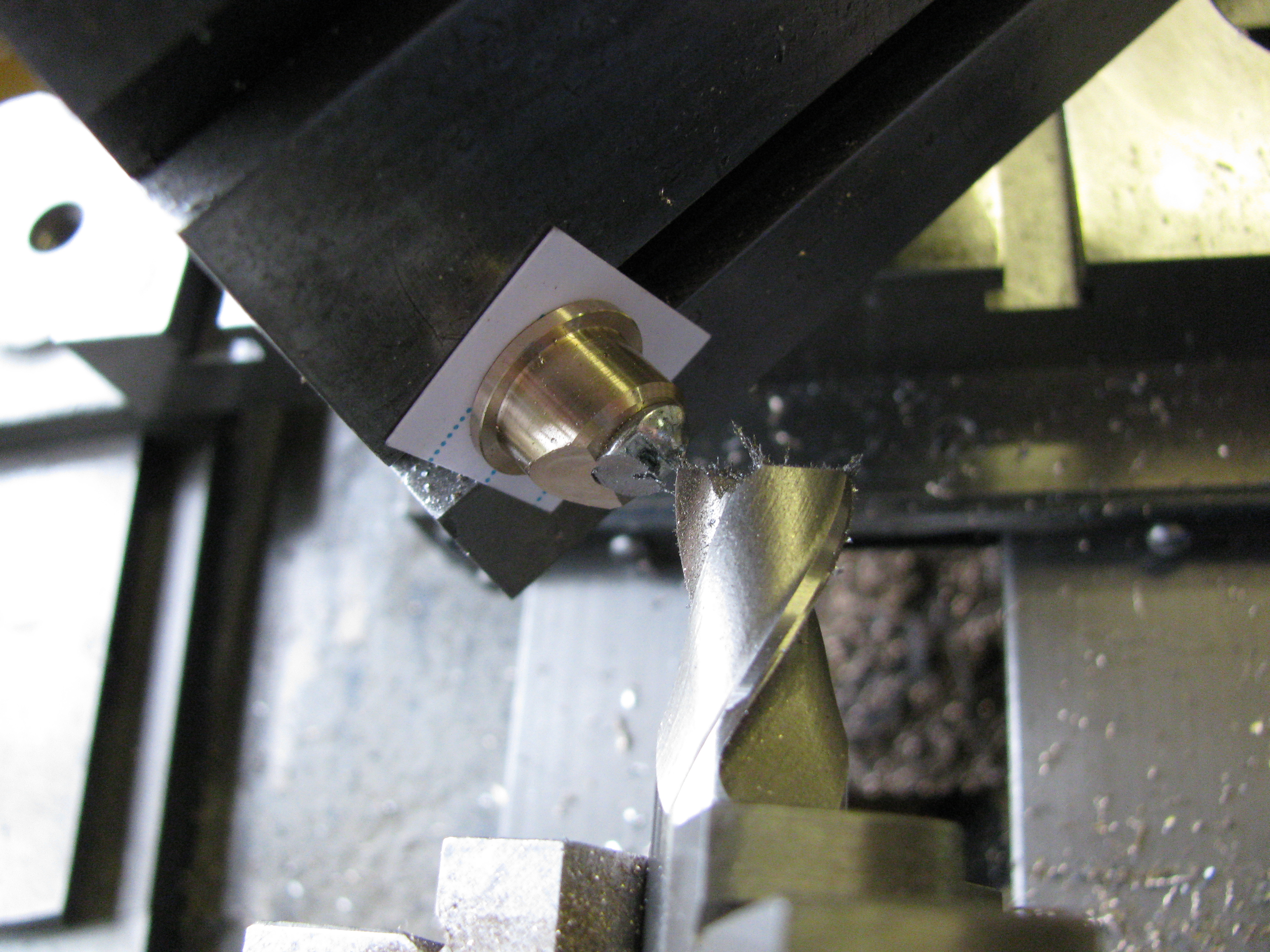
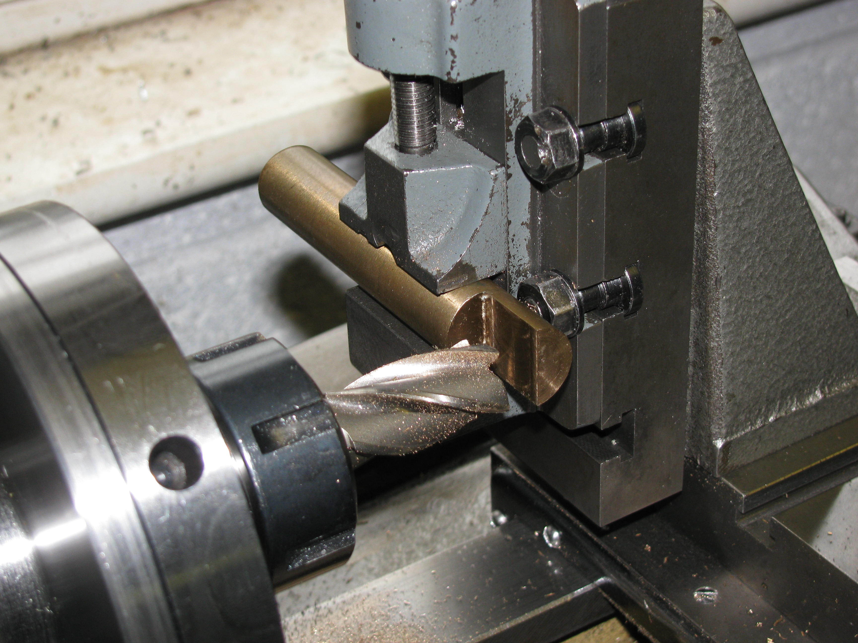
Using a slightly odd set-up, with a sacrificial M5 holding screw, I milled a flat on each bush at 45° for clearance for the tappets, and drilled oil holes in these faces at the same setting. The cap is a pleasing push fit in its recess, and other than deburing the oil holes where they break into the bores, no fitting was needed. Job's a good'un. (6½ hrs)
.