
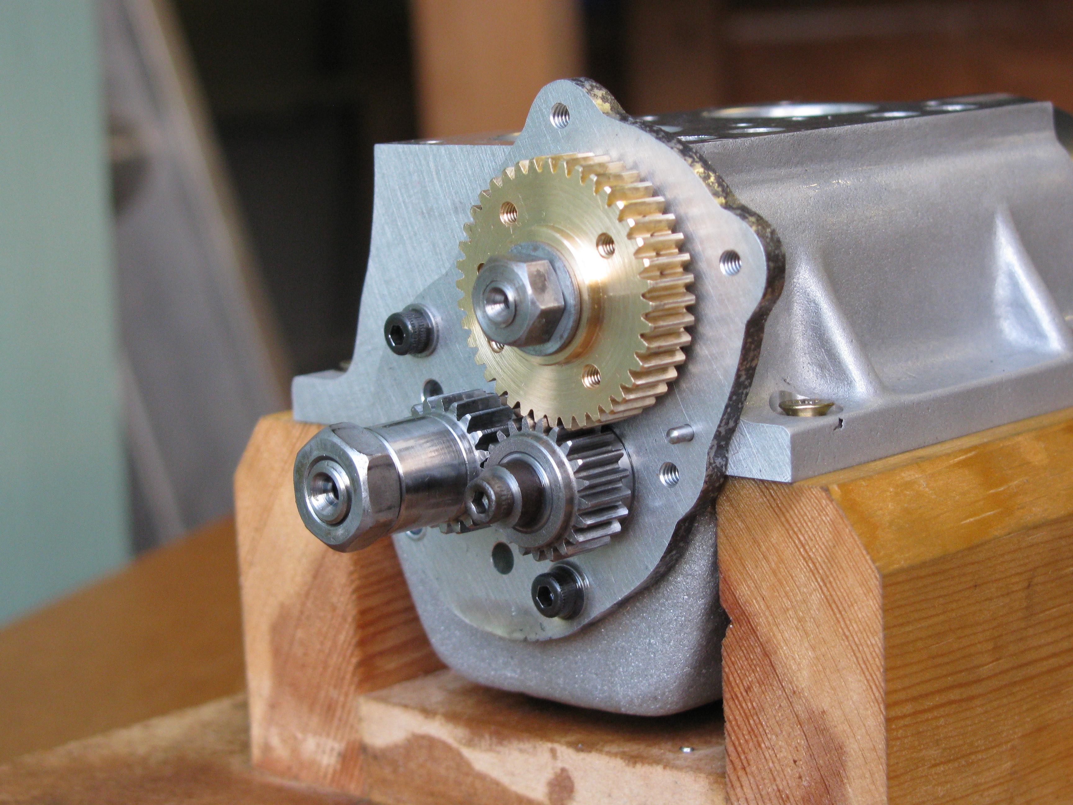
Timing Gears
There is a small typo in the original construction series: the pinions are labelled 20 DP, to mesh with a 40 DP gear. The design calls for a 20 tooth Crankshaft Pinion and Idler, and a 40 tooth Camshaft Gear. Clearly, they should all be 40 DP. Additionally, the Idler does not need a keyway.
The axial positioning of the teeth, across the width of the gears, does not make sense as drawn. Both the General Arrangement drawing and, towards the end of the series, a diagram showing how the Crankshaft Pinion can by pinned to the shaft, show the teeth outside and the shoulder inside. The teeth run immediately inside the Timing Case, and the drawing of the Idler, with a narrower inner shoulder to accommodate the thickness of the mounting stud, bears this out. However, if that is the case, the Camshaft Gear teeth would only engage with the Idler by 3⁄32″. Putting the Idler the other way round would give full engagement between it and the Camshaft Gear, but then it would only mesh with the Crankshaft Pinion by three quarters of their face width.
I am also unclear as to why the Camshaft Gear only has a 5⁄32″ face width when the pinions have ¼″. I can think of reasons for doing this, such as minimising the inertia of the gear, but none of them convinces me. I intend to rearrange things so that the gears all mesh over a ¼″ face width, centred within the 3⁄8″ space available within the Timing Case.
Early on, I decided that I would have preferred the Idler to have 19 or 21 teeth, to provide a 'hunting tooth' ensuring every tooth of each gear meshes with every tooth on its mating gear. This should help to prevent uneven wear developing. Also, I did not fancy the idea of case-hardening the Idler but was also not keen on having two soft mild steel gears meshing together. The availability, at moderate cost, of a suitable gear cutter from Tracy Tools clinched the matter: I would try making my own Idler Gear from scratch.
Laying out the gears with CAD allows the timing to be worked out accurately. I set it out with the camshaft arranged to have the key at the top at top dead centre, and aligned with a tooth on the timing gear, and with the crankshaft keyway aligned with the crankpins. This means that the particular geometry of the gears has to be accommodated by shifting the timing pinion keyway relative to its teeth. Noting that, because the engine is désaxé, TDC occurs not when the crankpins are directly above the mains, but when the crank throw is in line with con-rod, I found that, looking from the rear, the pinion keyway works out to be 1.21° clockwise from a tooth.
I have also changed the design of the Idler Stud as explained under the Timing End Bearing Housing.
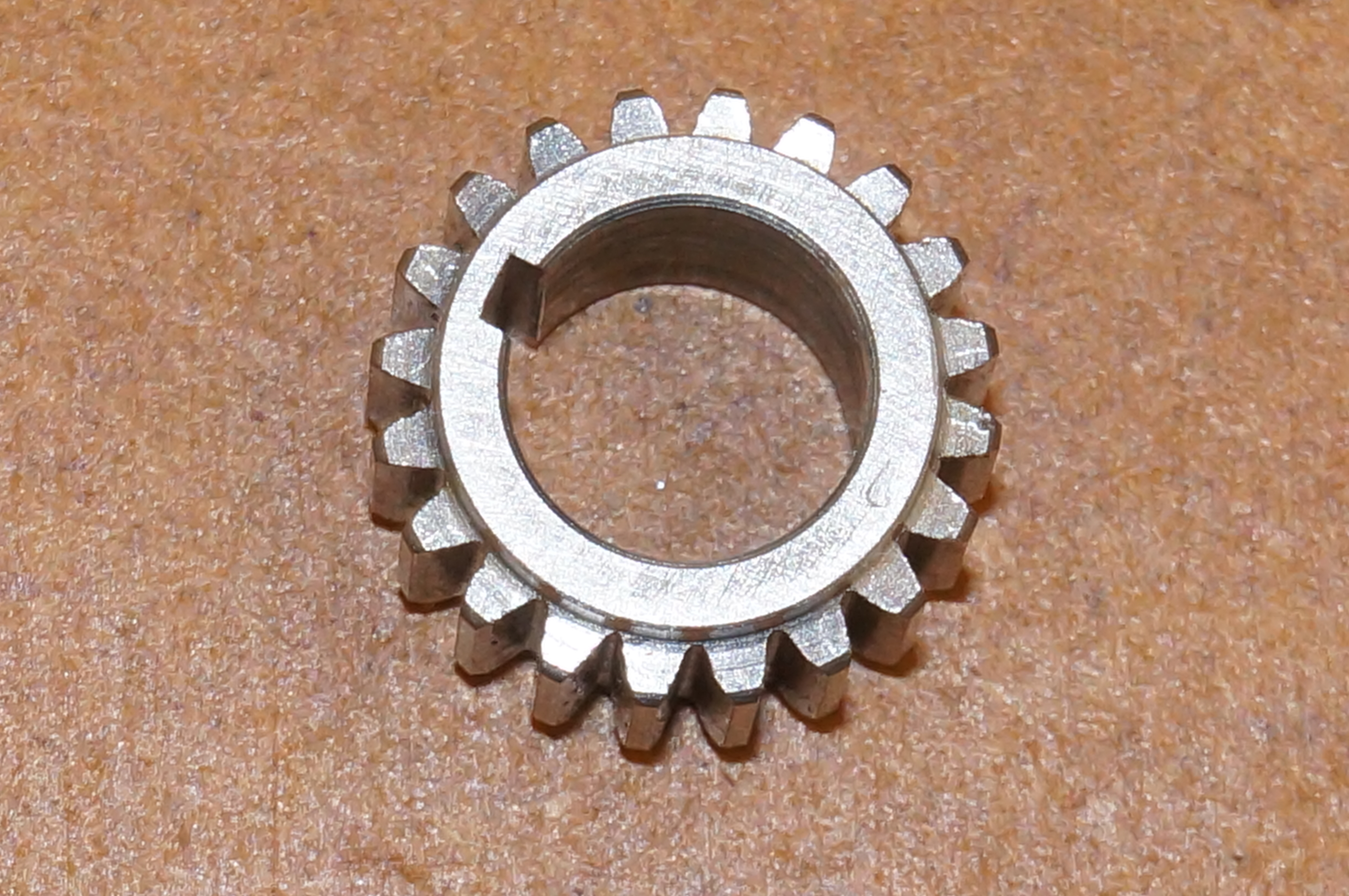
The gear blanks supplied with the kit were not terribly well made, and, compounded by my own incompetence, have presented some difficulties in producing a decent timing train.
2011-08-08 - Idler Gears and Dividing Head Adjustment

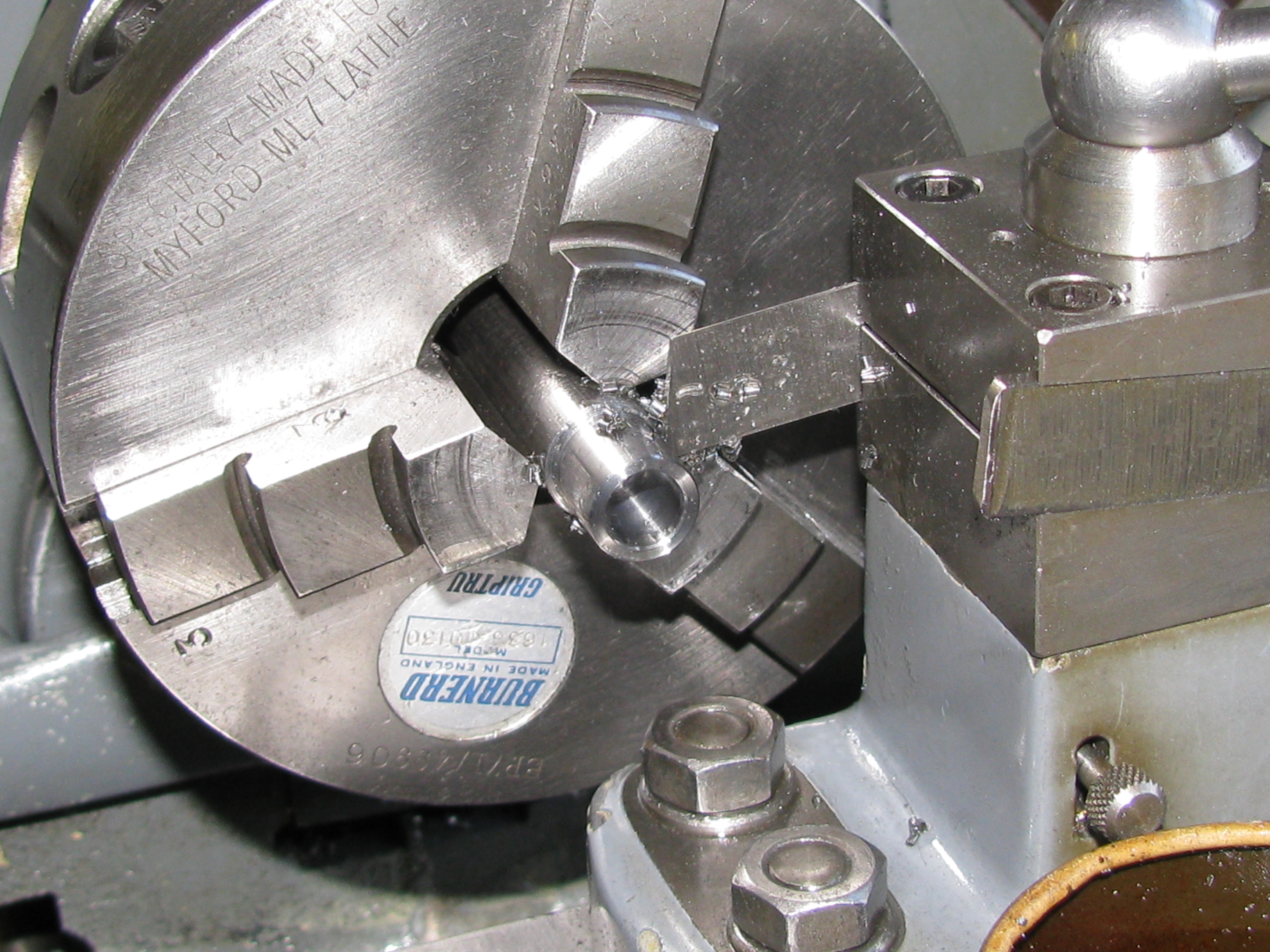
I decided to make two idler gears, one in mild steel and the other in 17-ton cast iron. The blanks were faced, centred, drilled, bored, reamed and chamfered. The reamed hole in the iron gear has rather more scoring than I would have liked, but there is plenty of good bearing area, and the scores will hold oil, or that is how I am arguing it, anyway. Soft jaws were used to hold the blanks for facing to length. After making some retaining washers, I turned a stub mandrel 0.3130″ to fit the reamed holes and put an M4 hole in the end. Using the mandrel, the outside diameters of the blanks were turned and shoulders and chamfers cut.
In checking the truth of the set-up for cutting the teeth, I found that the dividing head was introducing some errors. The worm was too tightly meshed with the wheel, which gave a cyclic error of more than 0.001″ The spindle was not firm in its split bearing in the body casting and the job was running about 0.004″ out. After removing the worm bracket, I tweaked the spindle bearing adjustment. I was then able to adjust the Griptru chuck to give about 0.0002″ run-out. I repositioned the adjustable worm bracket to minimise the cyclic error, which meant that I had to allow a very little backlash in some positions.
Getting the centrelines of the cutter and the blank in the same plane is a bit tricky. A check showed that I could rely on the cutter being symmetrical, and used a stack of slip gauges, half the difference between the cutter thickness and the blank diameter, to line them up. To zero the cut, I set the height to just kiss. I set a roughing cut to 45 thou and had 12 teeth cut on the iron blank by teatime. (4½ hours)
2011-08-09 - Finishing the Idler Gears and Starting the Pinion
I roughed the remaining teeth on the iron blank and went round again with a finishing cut, all at 90 rpm. For the steel blank I took a 49 thou roughing cut, leaving 5 for finishing, this time at 200 rpm. I have since read that it better preserves the cutter to take the whole lot in one go. It may well, but would it be as accurate, or the finish as good? After stripping down the gear cutting setup and remounting the chuck on the lathe spindle I adjusted it again to get the mandrel running true and took a light deburring cut on the back of the steel gear. Because they were finish turned while clamped on the mandrel, the front face of each gear has no chamfers. These were cut by rotating the gear between the fingers on the stationary mandrel.
After tidying up I started work on the Crankshaft Pinion. One of the problems with the supplied blank was that the OD was rather roughly machined so it was difficult to be sure of gripping it true. I tried gripping it in an ER collet to face the ends. This resulted in the end faces being 0.0004″ out of parallel, which is not good enough. When the retaining nut is tightened, it would distort the crankshaft. There was still a couple of thou left to rectify it, but I could not decide how best to do it. While chewing it over I gave the lathe a good clean down and oil round. (4½ hours)
2011-08-13 - Completing the Crankshaft Pinion
Even with the wide gripping range of ER collets, they are better when close to the nominal size, especially with a short part. The pinion should have fitted nicely in a 14mm collet, but at 9⁄16″ diameter, it was 12 thou over size and would not fit. I considered making a split chucking bush, but in the end decided on a 15mm collet. With the least possible amount of pinion proud of the collet, I took a shave off the face and opened the hole with drills and then a boring tool. As the bore was strangely coming out a bit tight at the mouth I decided to ream it - the seating on the Crankshaft has deliberately been made slightly oversize to allow this. After chamfering to clear the root radius on the Crankshaft, the fit was a bit loose, but good enough.
I put the 5⁄16″ stub mandrel, used for the Idler, back in the Griptru, set it true, and put the shoulders and chamfers on the pinion, again doing the internal chamfer by twiddling the gear by hand. On a rough trial assembly, the Crankshaft won't turn. I found the pinion end faces still 3 or 4 tenths out of parallel, which I pretty much cured with one rub on 400 grit paper. With a bit more care in assembly the shaft turns nicely. (3 hours)
2011-08-14 - The Crankshaft Sleeve
I cut off a piece of ½″ free cutting mild steel bar of sufficient length to provide a decent chucking piece, turned the OD and polished it to half a thou under the nominal 7⁄16″. After centring and drilling I bored it carefully, running the tool in both directions until the Crankshaft would just go in without wringing. (This is the fit I wanted on the Timing Pinion - perhaps I will try making up the spare.) Next, I chamfered inside and outside, parted off, reversed it in the chuck, protected with a thickness of notepaper and machined to other end. I had to adjust the Griptru again to cut even chamfers. The sleeve assembles firmly on the shaft and, very pleasingly, it turns sweetly with the Timing Case in place. (1½ hours)
2011-08-19 - Trial Assembly
Actually, trying it with all the Timing Case bolts tightened down, it is a bit stiff. I tried the effect of briefly turning the shaft with a drill-driver (driving the nut with a socket), but it did not have much effect. After a while a bit of black oil appeared out of the bearing and on dismantling there was no sign of any picking-up. So it will probably be OK to let it bed in later, though I need to be sure it is not fighting the timing-end main bearing. It is important to get the supplied ¼″BSF nut the right way round, as it only tightens square-on one way. This may be a good reason to make a starter dog at some stage.
Before I can move on to the Camshaft Gear, I need to finish machine the Camshaft so I can use it to fit the taper. (1 hour)
2011-08-30 - Facing the Camshaft Gear
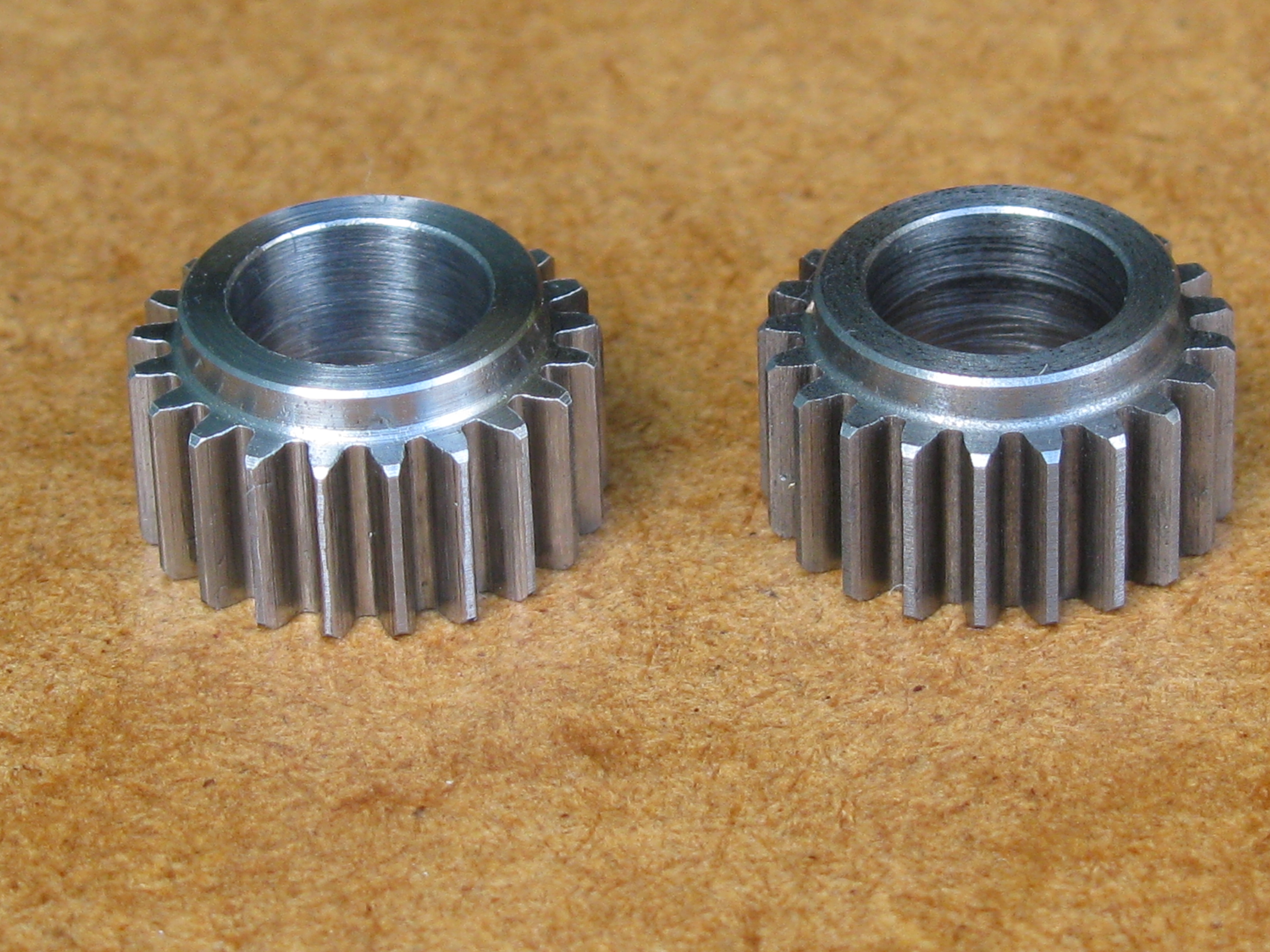
With the Camshaft finished, and a little boring tool freshly ground, I am now ready for the Camshaft Gear. The OD of the gear is not parallel. As can just be seen in the photo of the blanks at the top of this page, it seems to have been turned with a tool with a large radius that did not make it all the way, leaving an outward curve on the tooth crests. First, I machined a little step in the soft jaws on the 3-jaw chuck to take the blank, getting the bore to the right size more by luck than judgement. How are you supposed to measure it, other than by using the part as a gauge?
With the gear mounted in the chuck it soon became clear that concentricity was going to need investigating. With a run-out at the periphery of about ½ thou, the 3⁄16″ bore was showing up to 0.005″ TIR.
A narrow shoulder is required on the inside of the gear, so I took an exploratory cut. From bottoming out in the highest tooth root it took a further 2 thou to cover all of them. The blank was mounted with the out-turned tips outwards, and these showed a run-out of about 2 thou, but I would not want to rely on that. I took a facing cut and then another shoulder cut, which showed the highest roots were towards the No 1 chuck jaw. Should I work from the OD as I originally intended, or should I adjust the Griptru chuck to get the roots running true? It was fairly late anyway, so I decided to stop and have a ponder. (1 hour)
2011-09-08 - Completing the Camshaft Gear
The shoulder cut so far still leaves plenty of metal to allow it to be used as the outside of the gear, so I decided to turn the blank round and see what I could learn from that side. Using an 'elephant's foot' on the end of the DTI to ride over the teeth, I measured 2 thou run-out. On the theory that the tooth roots were a more important and more reliable indication than either the OD or the bore, I decided to work from them. Only later did it occur to me that I could have made a tip for the DTI to measure between the teeth at the nominal pitch circle diameter. I took another trial facing cut which showed the roots it be out by the same amount, in the same position on the gear. By adjusting the Griptru chuck to compensate for the run-out of the roots, it also brought the OD within ½ thou. There was now very little metal left for another test cut but what I was able to take was promising. I went ahead and faced the gear, finished the shoulder and put a small chamfer on the tips of the teeth.
Boring the taper with the taper turning attachment would require resetting it to run the other way. I was reluctant to do this so I took chuck off with the job in it, and mounted the flywheel turning mandrel between centres, and used the long taper on this to set the topslide to the same angle. The taper on the mandrel was not absolutely spot on concentric, as it had been turned in situ as a stub mandrel, but the taper would still be sufficiently accurately set. With the chuck and gear back in place, I bored the taper starting with cuts of 0.010″ and working down to 0.002″, using the Camshaft to check the taper with blue when getting near to size. I took all cuts with a second pass coming out of the hole. I checked the size with the Camshaft, measuring for the correct insertion depth. I stopped when this was 2 thou less than design, as it would have been very easy to go oversize with another cut, and this much would probably be taken up by tightening the retaining nut anyway. The taper blued up nicely, with a slight ridge detectable at one point, but not enough to worry about.
A final job at this setting was to cut the keyway. For simplicity, I decided to cut this straight rather than on the taper, so the keyway depth in each part varies along the length. Having ground a piece of broken parting-tool blade to fit down the hole, I set it on centre height, and aligned the gear teeth with the keyway by repeatedly comparing tool and tooth at 'front' and 'back', adjusting tool height and spindle rotation until happy. As it was a bit tricky to see, I checked the final position with a camera. This was still awkward, but smaller and easier to get into funny positions than my head. Once set up the slotting went pretty easily. For these jobs it seems that having some top-rake on the tool is a big help.
My ¼″ collet will hold the Camshaft by the timing end journal with enough clearance to fit the gear, so with that set-up I finished the spigot on the outside to take the magnet holder ring. I also skimmed a maximum of about 2 thou off the OD of the gear to clean up the original manufacturing fault.
Transferring the collet chuck to the dividing head, the Timing Ring fixing and dowel holes were drilled. Using the GHT Pillar Tool for tapping the holes, I found it surprisingly tough going, having to use second and plug taps part way through befor going back to the taper to again to carry on through. Admittedly though, at ¼″, the holes are a bit on the deep side for 8BA. (6 hours)
2011-09-10 - Dummy Idler Stud
I deburred the Timing Gear teeth and the keyway, but it there is still a notchy interference between the keyways when trying the fit on the Camshaft.
While having a think about the next stage, I made up a disc with three holes on a pitch circle to use as a puller for the flywheel.
I had decided to use a special stud to mount the Idler, and to use a toolmaker's button to find it's correct position on the Timing Plate, finding a position in which the gears meshed best. The first task was to locate the temporary tapped hole to hold the button. I decided to try a mild steel punch to dot the plate. I turned tis with a small point and a diameter of 5⁄16″ to fit in the Idler Gear. The punch made an adequate mark on the alloy plate, but it was then too much blunted to have done another. I drilled the hole in the drilling machine and tapped it in the Pillar Tool. Next I turned up the button, a spacer ring to go behind it, and a washer sized to hold the button in place with some positional latitude while allowing the Idler Gear to be slipped on and off.
I fitted everything up and adjusted the Idler button for reasonably smooth, tightish running, I tried it with an electric drill to turn the Crankshaft at a modest speed. I ran it briefly with a little Brasso on the gear teeth to try lapping them in a bit. There was a fair amount of variation in the meshing, and there were tight spots. I decided I needed to try to get the gears running better before finalising the position for the Idler. I stripped everything down, carefully cleaned and reassembled. (5½ hours)
.
2011-09-12 - The Spare Pinion Started

Now that the 21 tooth Idler Pinions have been made successfully, there is a spare 20 tooth pinion, and I decided to use this to see if I could do a better job on the Crankshaft Pinion. After deburring the blank, it was noticeable that the tips of the teeth were very unequal in width. After the concentricity errors found on the gear, I decided to work from the roots on this pinion too. I also thought more care was needed in holding it square, so I decided to make a cup with an internal shoulder to register the blank and an external one to bed against the chuck jaws. Again this pinion is 13 thou over size. Bar for the cup was faced and turned to a shoulder and parted off. Reversed in the chuck, it was faced, drilled through, and bored to the internal shoulder to take the gear and relieved slightly at the bottom of the hole. After receiving a pop mark on the face at No.1 chuck jaw, it was removed, slit with a hacksaw and deburred.
Fortunately, there is a reasonable amount of length available on this blank for making trial cuts. With the blank mounted in the cup, the first shoulder cut first reached the root by No.3 jaw, and it took a further 6 thou feed to bottom all round, the lowest being between jaws 1 & 2, as expected. I turned the OD of the cup just enough to provide a reference diameter, and adjusted the Griptru to give this diameter 0.16mm wobble in the right direction (my lever-type DTI is metric). Another cut gives the high point now between jaws 1 and 2, and it takes just 1 thou feed to clean up all round. The diameter to clear the roots is 0.443″, which is pretty close to the nominal 0.442″, and knocks on the head any slight suspicion that the oversise OD is a result of addendum modification. Nonetheless, as the OD is oversize, the teeth seem to be too deep, and a trim on the tips would do no harm. At this setting I faced the back of the gear and turned the inside shoulder. Next, I dismantled the engine again to use the Crankshaft to gauge the pinion bore. (3 hours)
2011-09-15 - The Spare Pinion Finished
After making up a couple of ¼″ boring tools from silver steel blanks, I drilled the pinion 7mm and bored it out to a good fit on the Crankshaft and cut the important chamfer on the bore to clear the radius at the root of the Crankshaft shoulder. I reversed the gear in the cup and faced the outer end, managing to get it 0.002″ short, and not quite square. I set the stub-mandrel in the Griptru chuck as before, within 0.0005″. With the pinion mounted on the mandrel it showed 0.006″ run-out. I took a cut sufficient to cleaned up the OD, leaving it 2½″ thou over the nominal 0.550″ diameter, turned the shoulder and the chamfers. I deburred the teeth and lapped the outer face parallel to the inner to within a couple of tenths of a thou. This left the pinion a shade under length, but there is no need for a highly accurate size.
I made some temporary spacers to locate the Camshaft endways, and put all the parts back together. The next job is to make the Drive Coupling so that I can try lapping the gears together. (3½ hours)
2011-10-16 - Roughing-out the Idler Stud
Today I started by roughing out the Idler Mounting Stud from a cap-head bolt. Unusually, I tried a carbide tool, at about 150 ft/min. It did give a good finish. (¾ hour)
2011-11-04 - Fitting the Camshaft Gear
After cutting they keyway, the fit of the Timing Gear on the Camshaft was very notchy as the keyways crossed, and blueing up showed ridges in the wheel along the edges of the keyway. I tuned this up with scraper, file and a rub with Brasso to get a fairly smooth feel and a good thin even coat of blue. The flywheel end Camshaft Bearing has nothing to retain it at the moment so I made up a little temporary clip from a bit of soft spring steel. (2 hours)
2011-11-05 - Dog and Bone Coupling
Using the remnant of some rather nasty, not-very-free-cutting 5⁄16″ mild steel bar, I made four washers to fit in the couterbored engine mounting holes in the crankcase. With the same bar I made a temporary drive shaft, to fit the flexible coupling at one end, and with a spherical end and cross-pin at the other. From a short piece of 5⁄8″ mild steel, I made a matching drive dog to fit in the lathe chuck, with a bore to fit the ball and a slot across the diameter to fit the pin.
The keyway in the Camshaft, milled with a 1⁄16″ slot-drill turned out a little over size, an easy fit on a piece of 1⁄16″ nominal, 0.064″ actual, gauge plate. The keyway in the gear, meanwhile, is barey 0.062″ wide. I filed up a rather rough temporary key, good enough to ensure the shaft and gear assembled in the correct relative positions. (5 hours)
2011-11-09 - Engine Mounts
I milled and drilled and tapped some odd bits of shallow aluminium channel to make temporary engine mounts, prepared a baseplate in MDF, and made some alloy strips to clamp the two together. (2¼ hours)
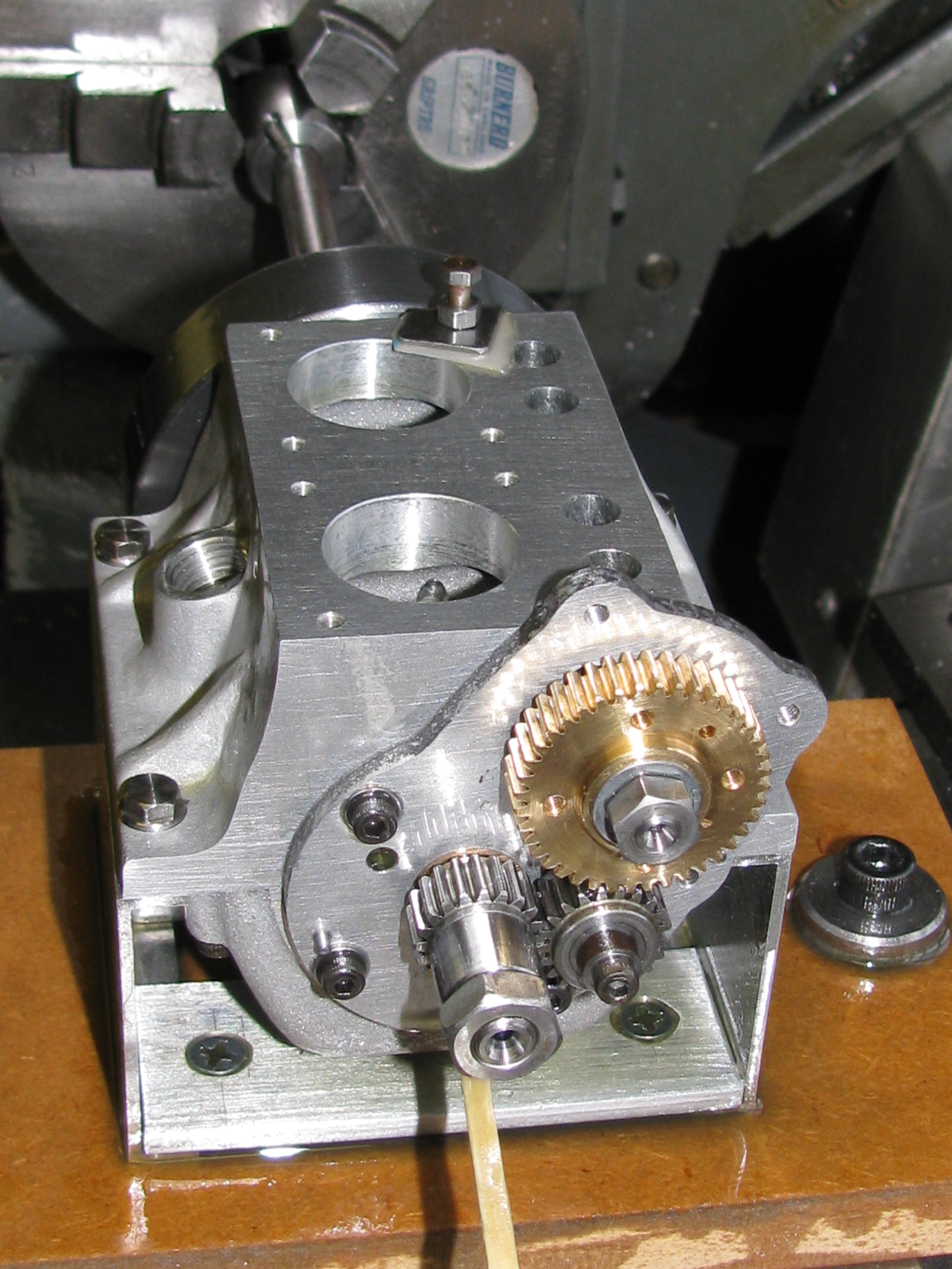
2011-11-11 - Lapping
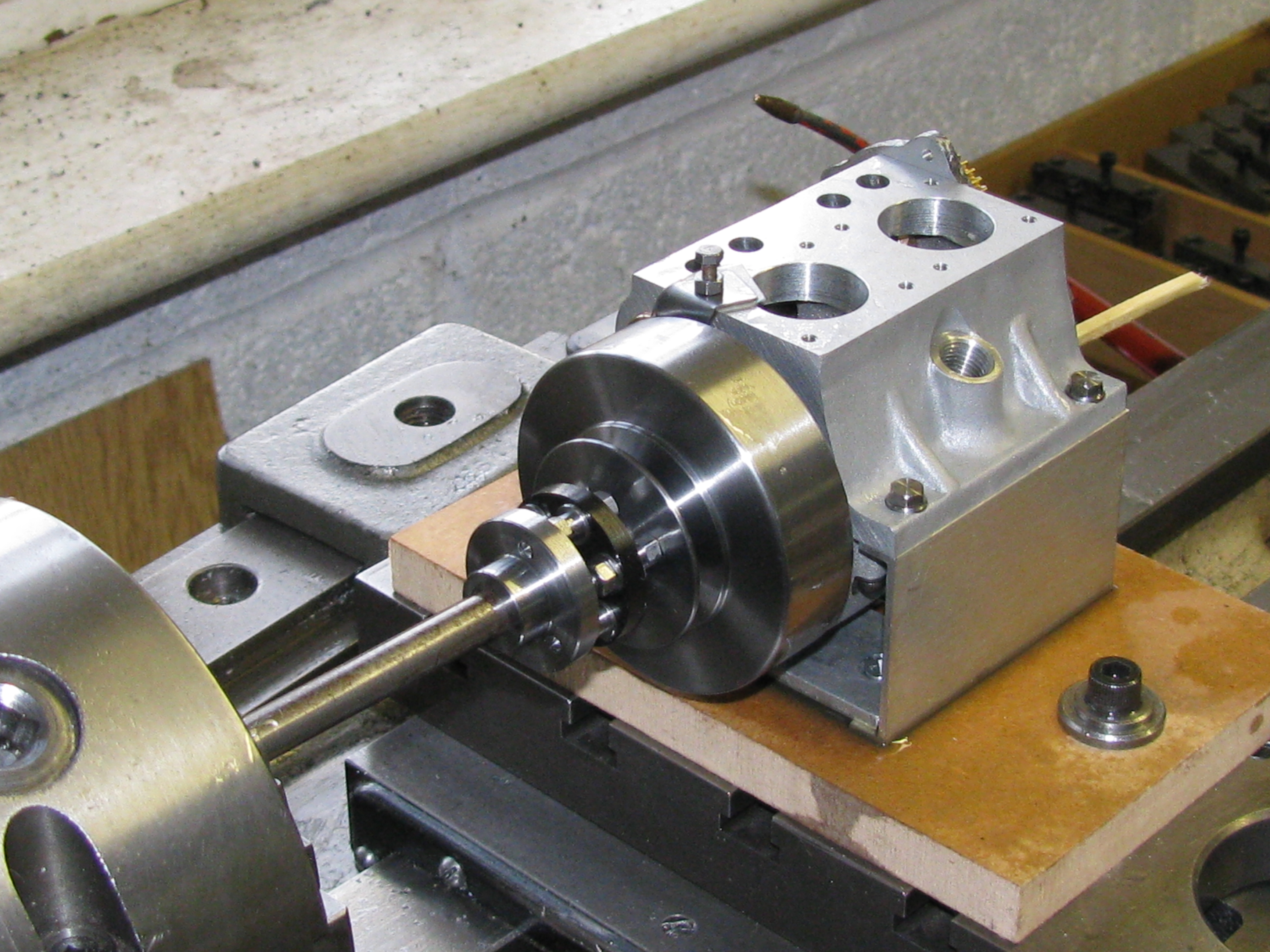
With everything assembled and set up on the cross-slide, I started gentle lapping with Brasso applied by brush to the gears while turning over at 200 rpm. It seemed to need something rather more aggressive so I moved on to 800 grit garnet. The running of the gears improved gradually. I noticed that a burr had been thrown on the brass gear, at the tooth tip, on one side, for about the outer third of the face width. Removing the burrs with a stone improved the running. Further examination showed that on the opposite flanks the gear was bedding in at the inner end of the teeth, showing that the teeth are cut slightly skewed. Taking the iron Idler off for examination showed little change. I regularly adjusted the position of the so that the gears were running with a definite tight patch in the rotation. After about one and a half hours running I stopped to examine the Crankshaft Pinion. At this stage the bore of the Idler had been polished up a bit, and the Camshaft did not feel quite right, so I decided it was time to strip down and examine. The oil drained from the crankcase brought out a small amount of greyish cloudiness. (3 hours)
2011-11-12 - Running In

On dismantling I found that a complete strip down was needed as some abrasive has got into the rear bearings. The front and centre Crankshaft bearings were fine, but there was a little bit of damage to the rear journal. Set up with the front end in a collet, I polished the rear end with 1200 grit wet-or-dry to 0.0003″ under size. The Camshaft only needed a very slight polish and is still dead on size. The bearings were carefully cleaned and washed and the gears were given an ultrasonic bath too. No more abrasives round here, then.
I reassembled the engine and put it back on the on the lathe to run for a while with just oil. I ran for a while at 600 rpm, and briefly up to 1500. With a fairly full sump it is good to see that quite a bit of oil gets pumped out through the oil transfer hole above the Idler Pinion, and provides ample lubrication of the gears.
The gears are not mating across the full face width, though the two pinions seem to run well together. They are running smoothly, without tight spots and are pretty quiet. I can now fix the final position of the Idler Stud. I put a smaller washer to hold the Idler button so that the Idler Pinion can be removed without moving the button, and re-adjusted its position again for smooth running and a minimum of backlash. Leaving the button in place, I dismantled again to get the Timing-end Bearing Housing out for boring.
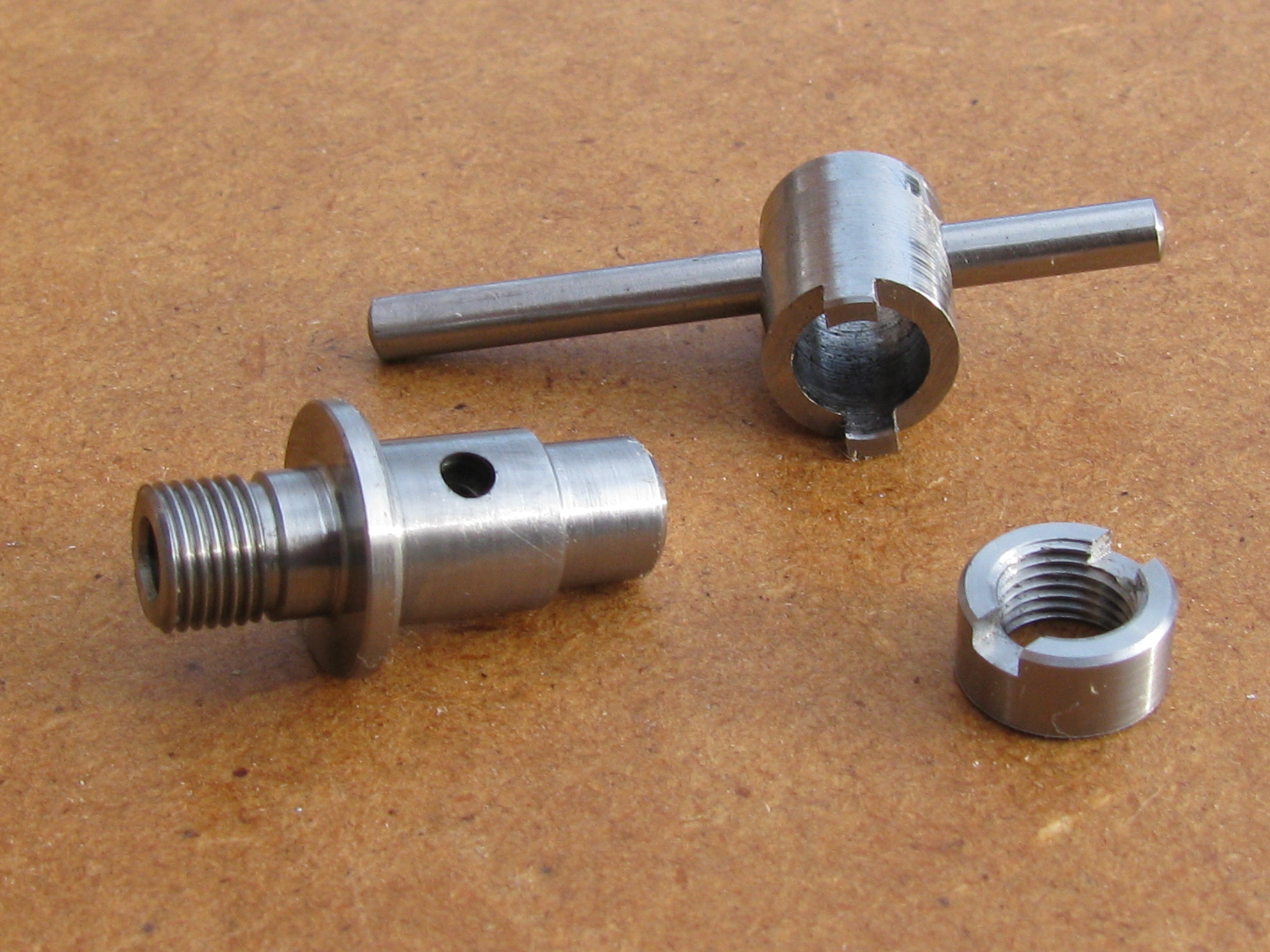
Moving on to the Idler Stud, this will have a nut with a slot across the face for tightening as there is no room to get a tool round the outside. A special spanner with a pair of dogs is needed to tighten the nut. I turned the nut and the body of the wrench as one piece and parted off from the parent bar. Clocked up in the Griptru chuck, I drilled through and tapped the nut ¼″ × 40 tpi, put chamfers on and parted off the nut. I drilled out the remaining wrench body to ¼″ and faced and chamfered both ends. Griping the already roughed-out Idler Stud, I turned and faced the flange and turned the locating diameter to ¼″ and trimmed it to length. (6¼ hours)
2011-11-13 - Idler Stud and Wrench
Continuing with the Idler Stud, I turned the thread runout groove and chamfer and screwcut the thread. Trying the nut at a thou short of the full thread depth, mildly annoyingly it went on, so the tap must be cutting well over size. I took a single light pass with a 40 tpi chaser to put at least some radius on the crests, and drilled the oil hole down the centre of the stud.
Back with the wrench body, I milled the dogs and started setting it up for drilling the cross hole for the tommy bar. (1½ hours)
2011-11-21 - Completing the Idler Stud
First, I completed the wrench by drilling the cross hole, and making up a tommy bar to suit.
Next, I made up a stub mandrel with a ¼″ × 40 thread to take the nut. With the stub in the chuck I transferred it to the dividing head, as a convenient way of holding it for slotting the face. At the first cut, the nut almost immediately unscrewed, getting well chewed up and breaking my only 3⁄32″ slot drill. As I would now need the stub mandrel again, I turned its OD so it could be clocked up again running true. I parted-off a piece of bar for another nut. Deciding to work the other way round for this one, I faced, turned, chamfered and drilled it, and set it up in the dividing head again for slotting, for which I used a 2.5 mm cutter taking cuts at 180° to get the slot to width and central. With the chuck back on the spindle I tapped the hole and parted-off the nut. With the stub mandrel back in the chuck and running true, I put the nut on, slotted face inwards, faced it to length and cut the chamfers. Nut done.
To machine the outboard end of the Idler Stud I made an accurate chucking bush to hold it by the already finished thread, register diameter, and flange face. Turning the bearing diameter of the stub shaft, at 0.3137″ diameter, the Idler Pinion almost goes on. I tried a tiny cut at the outer end (to be reduced later), but this took it down to 0.313″ which was too easy a fit. Lapping would be ideal, but for this I settled for polishing with 1200 grit wet-or-dry, bringing the diameter down to a running fit without tight spots at 0.3133″. I took a final shave off the flange face to bring the flange to final thickness, and faced to overall length, nearly misreading the depth mic again. Finally I turned the outer spigot diameter to 0.2501″.
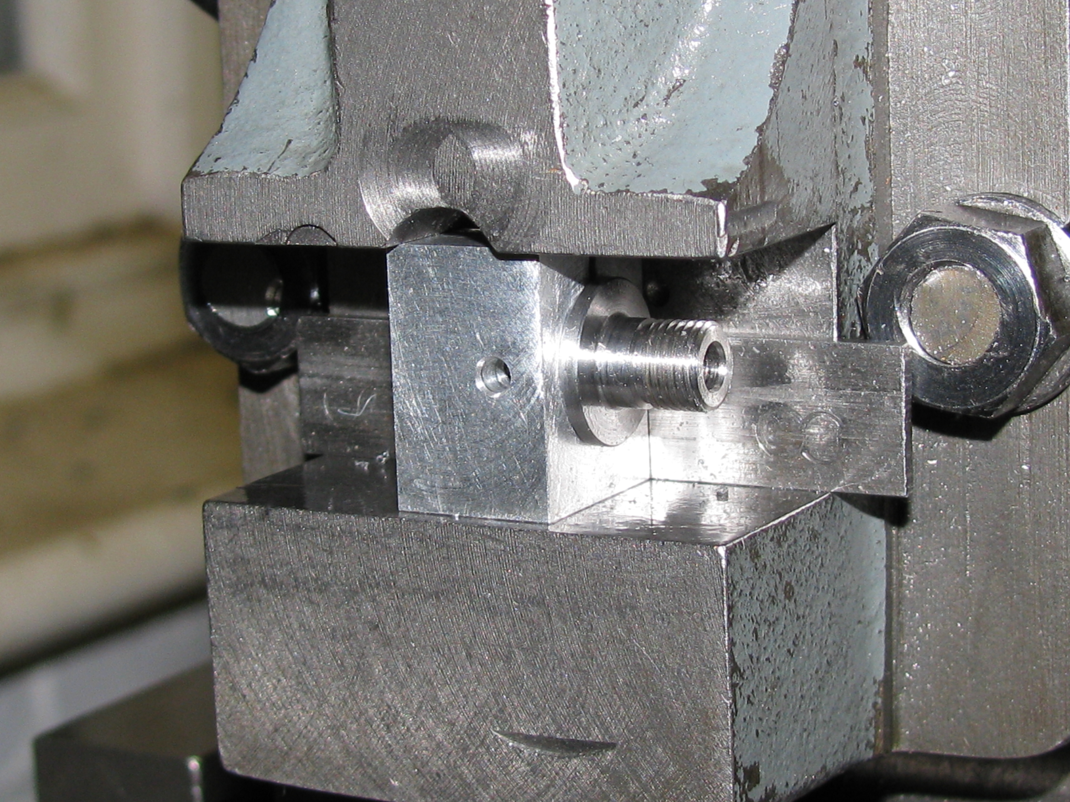
In the vertical slide I milled an alloy cube and drilled and reamed it 5⁄16″ and hacksawed a slit. As the slide has not been moved, when the block is put back in the machine vice, rotated 90° and with the Idler Stud, the hole and Stud have to be still on centre height. All this to drill the radial oil hole in the stud. The tricky bit is carefully polishing up the slight burr on the running surface.
The next job is to make the hole for the Idler Stud. This passes through the Timing Case and Bearing Housing, and a clearance hole is needed for the nut, lying on the joint between the Crankcase and Sump.
.
2013-01-06 - Preparing to re-cut the Camshaft Gear
With the Idler Stud made and fitted I found that I had ended up with the Idler Pinion and Camshaft Gear too tightly meshed. This was not helped by the imprecise cutting of the gear. I concluded that the best way to proceed would be to shave a bit off the teeth. Unfortunately I have not been able to find the right commercial milling cutter at an affordable price, so I have made one. I don't want to go in to that at length here, but I will mention that I have followed the methods set out in Ivan Law's book, but have decided for myself on the arc radius approximating to the correct involute tooth form. Briefly, a tool is made with accurately spaced hardened buttons, and this is used to form the profile on the cutter disk. The disk then has its bore opened out eccentrically and a section is cut away to form a single tooth. Interspersed with other jobs, over the last few days it has taken me about 6 hours to make the button tool, and another 6 to make the cutter and to adapt a bought blank taper mandrel to hold it.
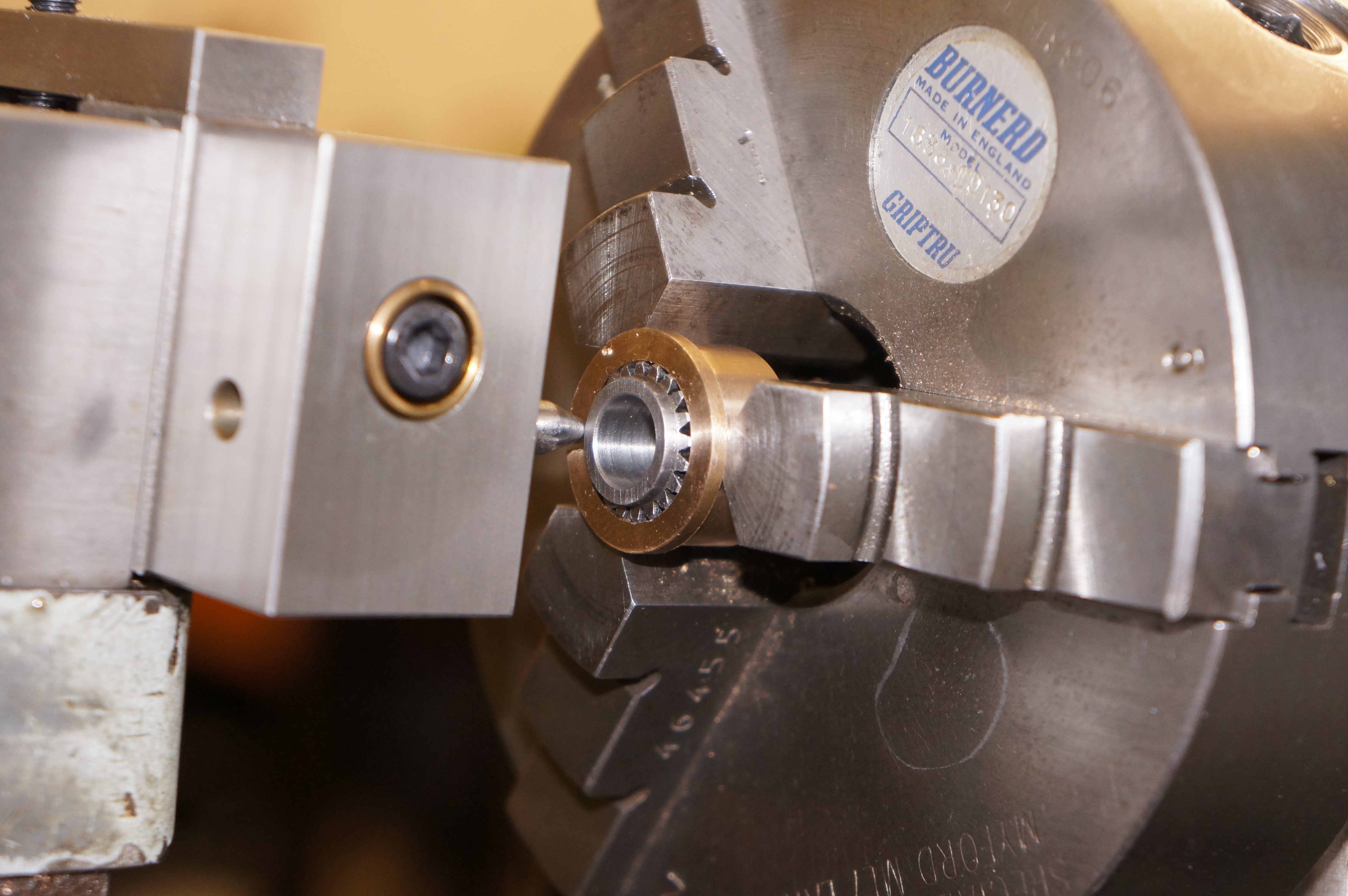
I had no way of measuring the gear so I had to take a little at a time until it ran smoothly. I needed to do trial assemblies to check progress with re-cutting the gear, so it seemed a good time to Loctite the bearing in place in the bearing housing. I did this as before, with the light axial clamping to ensure the bearing was sitting square. Then I changed my mind. I had intended to use the camshaft to cut the gear in-situ, but, because of the need to do repeated assembly trials, and because getting the camshaft out is a long-winded process, I decided to make a tapered stub mandrel for the purpose instead. For speed, I cut the 2-BA thread with a die. The finished taper blued up nicely on the bore of the gear (I have not moved the taper turning attachment since making the crankshaft).
Trying the gear in place, it was binding before it was fully home on the taper, so getting to a point where it seated comfortably would be a good guide to progress.
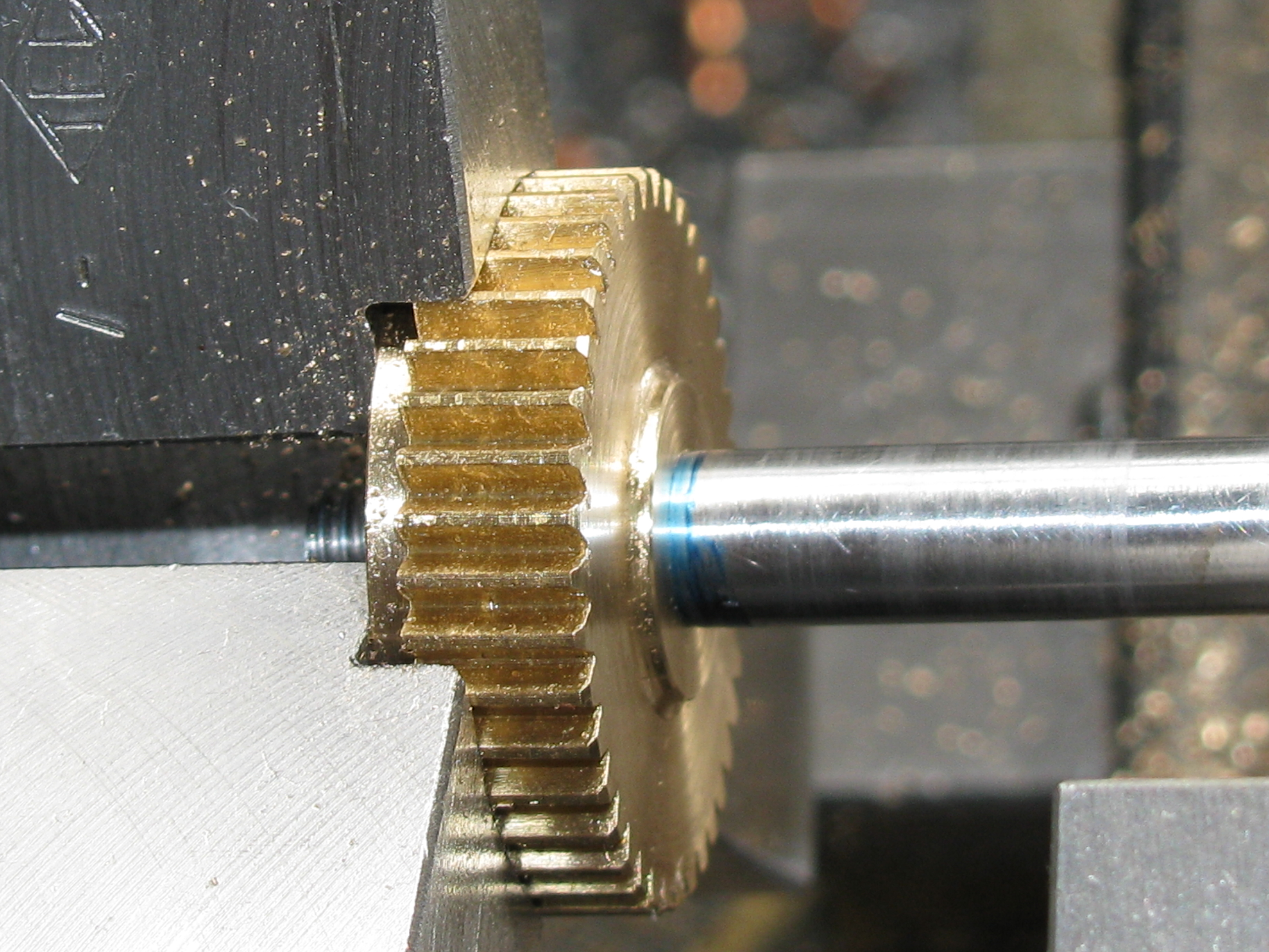
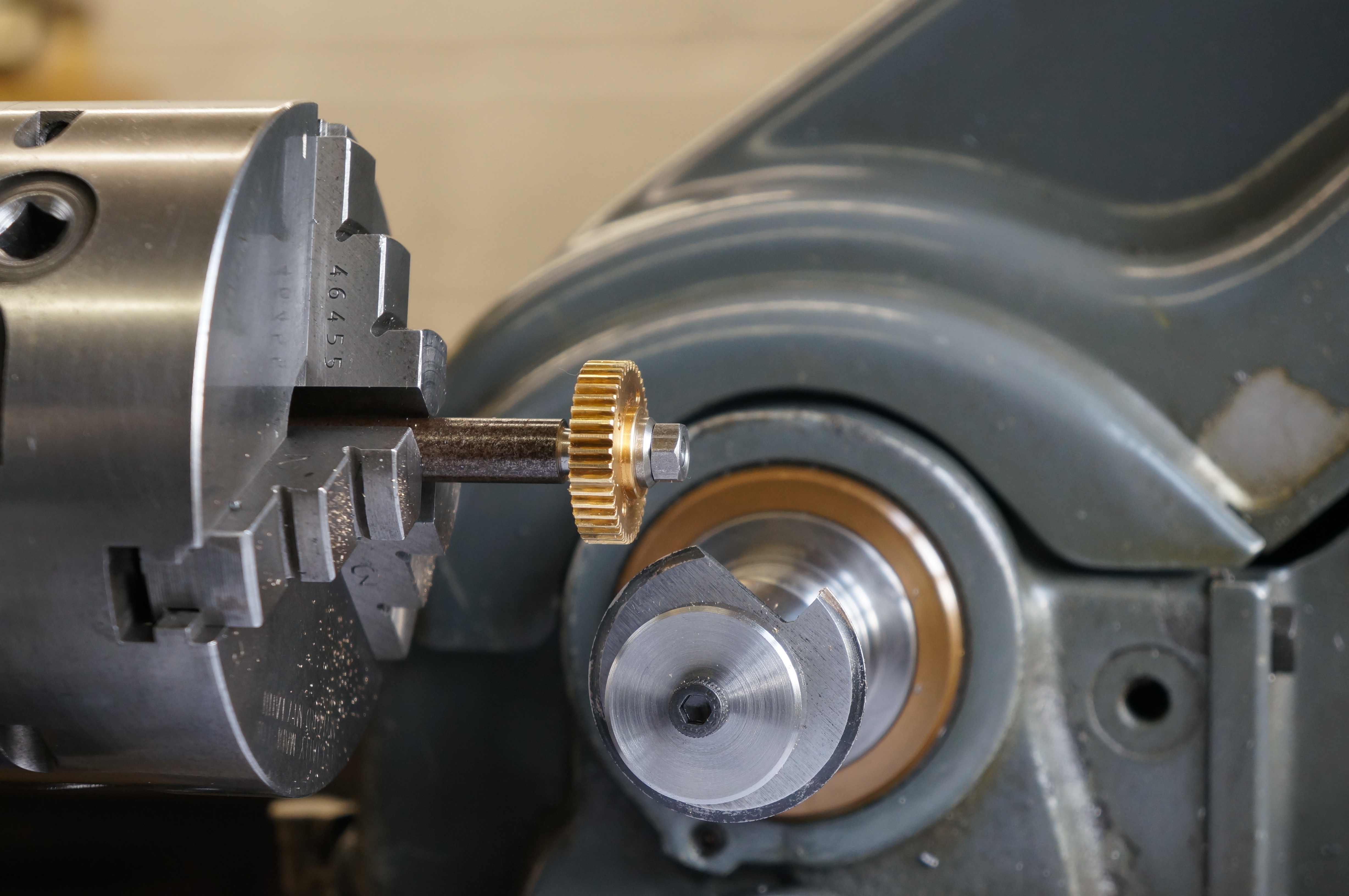
In Setting up for cutting the teeth, the Griptru chuck sits on the dividing head a bit out from its position on the lathe spindle so I readjusted it to get the mandrel taper running within a couple of tenths. Aligning the mandrel and cutter centres was done using a flat strip and feeler gauges each side of the cutter disc.
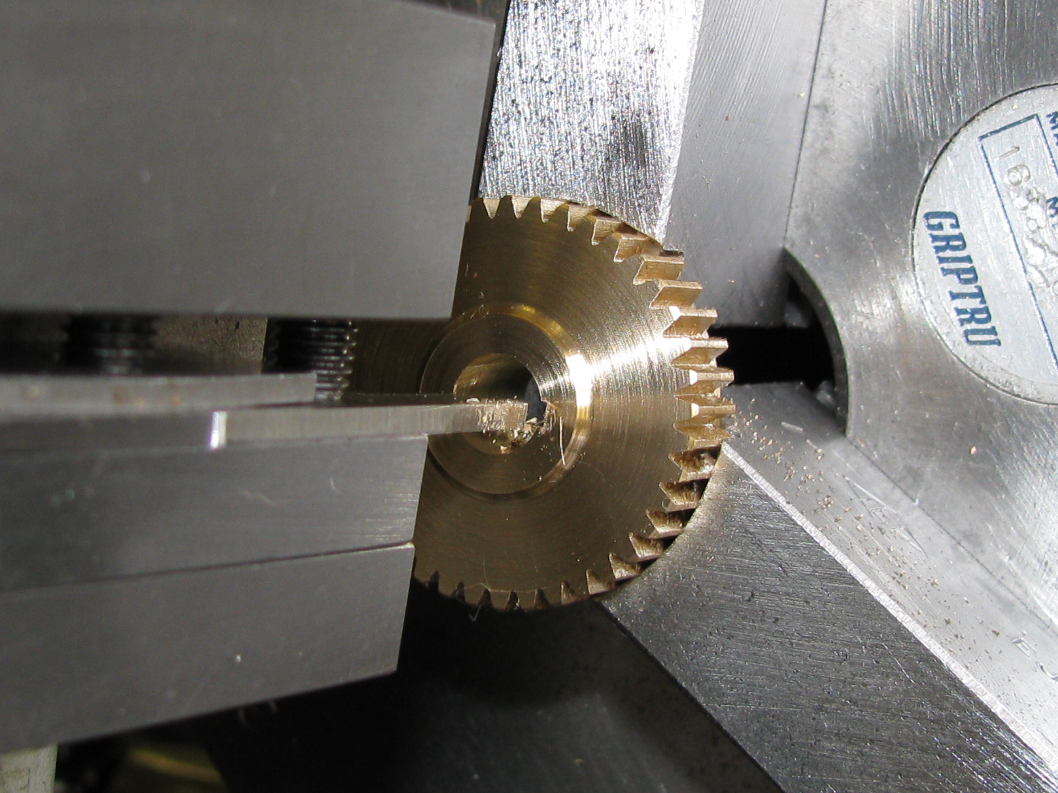
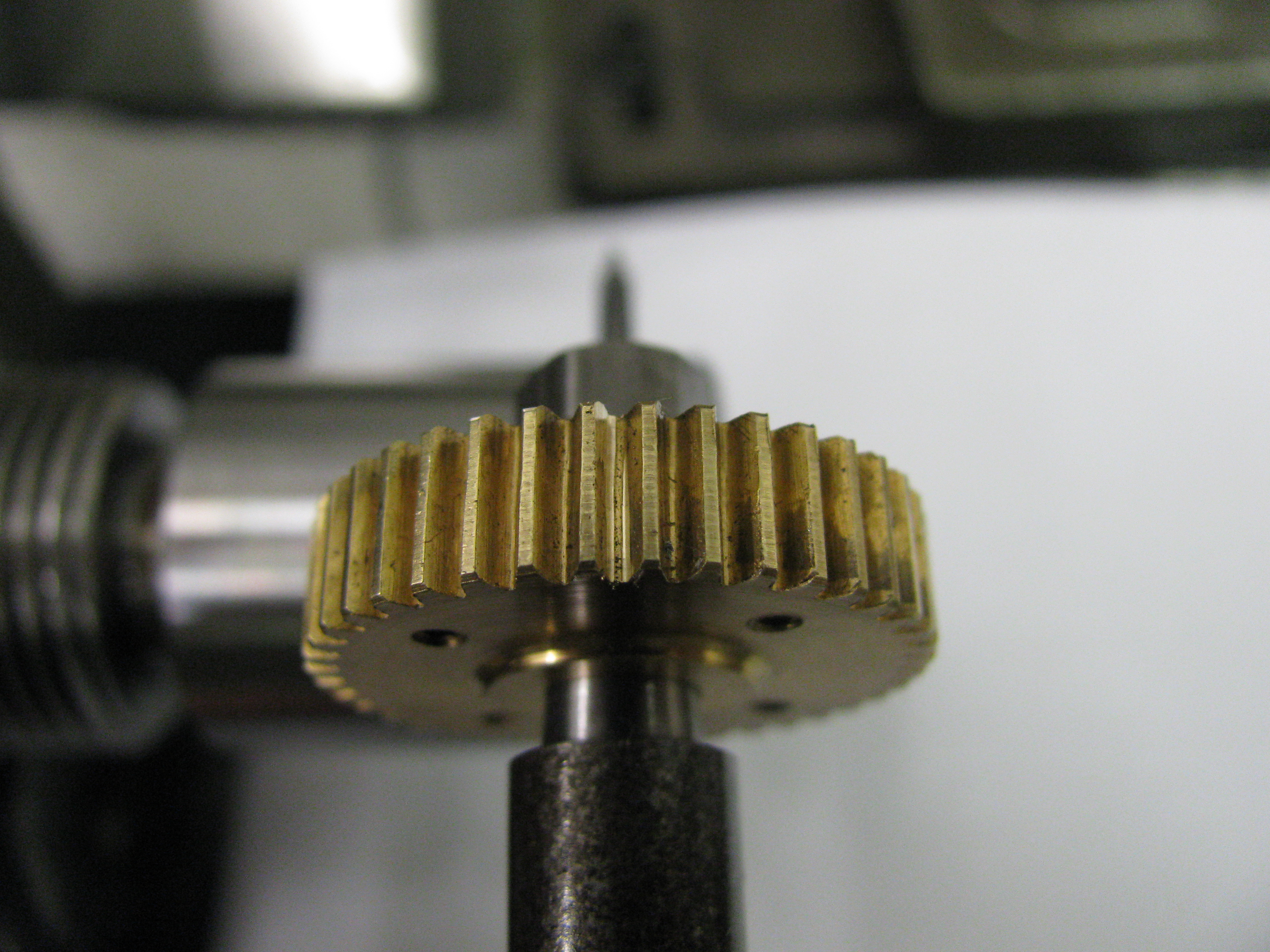
Finally I took a tentative cut to establish a starting depth of cut, using the camera to get close ups. In the photo, the nearest tooth space shows brightness on tooth roots and the upper end of the tooth flank to the left of the space, confirming that the teeth have been cut slightly skewed. (5¾ hours)
2013-01-07 - Re-cutting the Camshaft Gear
After one round the roots were cut nearly to the bottom and a bit was taken off low down the flanks in parts, reducing the skew a little. It fits better but it is not enough. After two more rounds, with 0.001″ feed on each, it is better, but still too tight. Cutting is still on opposite ends of opposite flanks. Two further rounds with a 0.002″ cut get it a good deal nearer, but not yet a fit. With another 2 thou it will just go round, but this cut seemed to remove very little metal. I honed the edge of the cutter and tried again at the same setting. This was cutting so I decided to got round again at this setting. I could feel and hear the tool beginning to thump more on each cut, and resharpened it twice more during the cut (once after hitting a chuck jaw). Trying this, it was a bit too tight for half a turn, and good for half a turn, with a little backlash at one point and one where it would not go without forcing it. After marking the tight spot I took another light shave over the tightest four teeth.
I think this must have been the wrong day to be doing this job because on more than one occasion I failed to back out of the cut far enough before indexing, so I have several teeth with a bit missing out of the corner.
Rashly, I tried a little fine grinding paste on the tight teeth and worked them by hand, but really even 400 grit paste is too coarse for these little teeth. After cleaning I used a slow drill-driver to run the gears for a couple of bursts of a few seconds with plenty of oil. This loosened the tight patch a bit more. (6¾ hours)
2013-01-09 - Will it do?
The timing gear meshing is now not brilliant, but it is OK. I ran them again with a drill for about a minute. They throw off quite a lot of gunge, so really they need running in an oil bath. There is still a slight notchiness detectable, but I think it should go fairly quickly. Because I used a bit of grinding paste I will stick them in the ultrasonic bath before assembly.
Despite the uneven depth due to the cutter losing it's edge, and despite the nibbled teeth (on the less important trailing flanks) this gear will have to do, at least for now. I am not going to try to make a replacement from scratch at this stage. Strip the set-up down, clean and tidy up. (1¼ hours)
2013-01-19 - Pinion keyway
I decided that this job should be done before cutting the crankshaft keyway. It would be easier to mill the crankshaft to suit the width of the keyway in the gear than to work the other way. I machined a new cup to hold the pinion, and made a point on the end of a short piece of silver steel to locate in a tooth space for setting the keyway at the right angle. Thinking this pin might be good for other jobs, I hardened and tempered it.
Having tried the slotting tool (a broken 1⁄16″ wide parting tool again) in a toolholder I decided it would be better to turn it over and cut at the back as I thought this would make it easier to set it to centre height. I turned it over and clamped it too tightly, shattering the blade. This prompted a tool grinding session. (5 hours)
2013-01-20 - Pinion keyway


I set the replacement slotting tool up in the toolholder with some brass shim to support it and to equalise the clearance top and bottom. I used a disc in the chuck to set the tool accurately to centre height using the half-turn, compare and adjust method. With the toolholder adjusted it could be swapped for a boring toolholder with the pointed locating pin. I adjusted this for centre height using the centre height gauge.
With the dividing head set up on the back of the lathe spindle, the pinion sitting in the cup, and the pin located in a tooth gap, I could then tighten the chuck.
I could not get the exact 1.21° offset from the layout drawing, but 1.2° is quite sufficient. This is 1/300 of a turn, achieved with 9 divisions on the 45 hole circle, plus 1½ turns of the handle to get the 9° between gap and tooth.
With the angle correctly set, the toolholders could be swapped again to put the slotting tool back, and the slotting handle set up. I rotated the toolpost one division (2½°) to provide front clearance on the slotting tool. I cut the slot to the correct dial reading, as it was pretty well impossible to measure in-situ without disconnecting the slotting lever. It turned out to be about 0.004″ over, which is OK. (3 hours)
.