
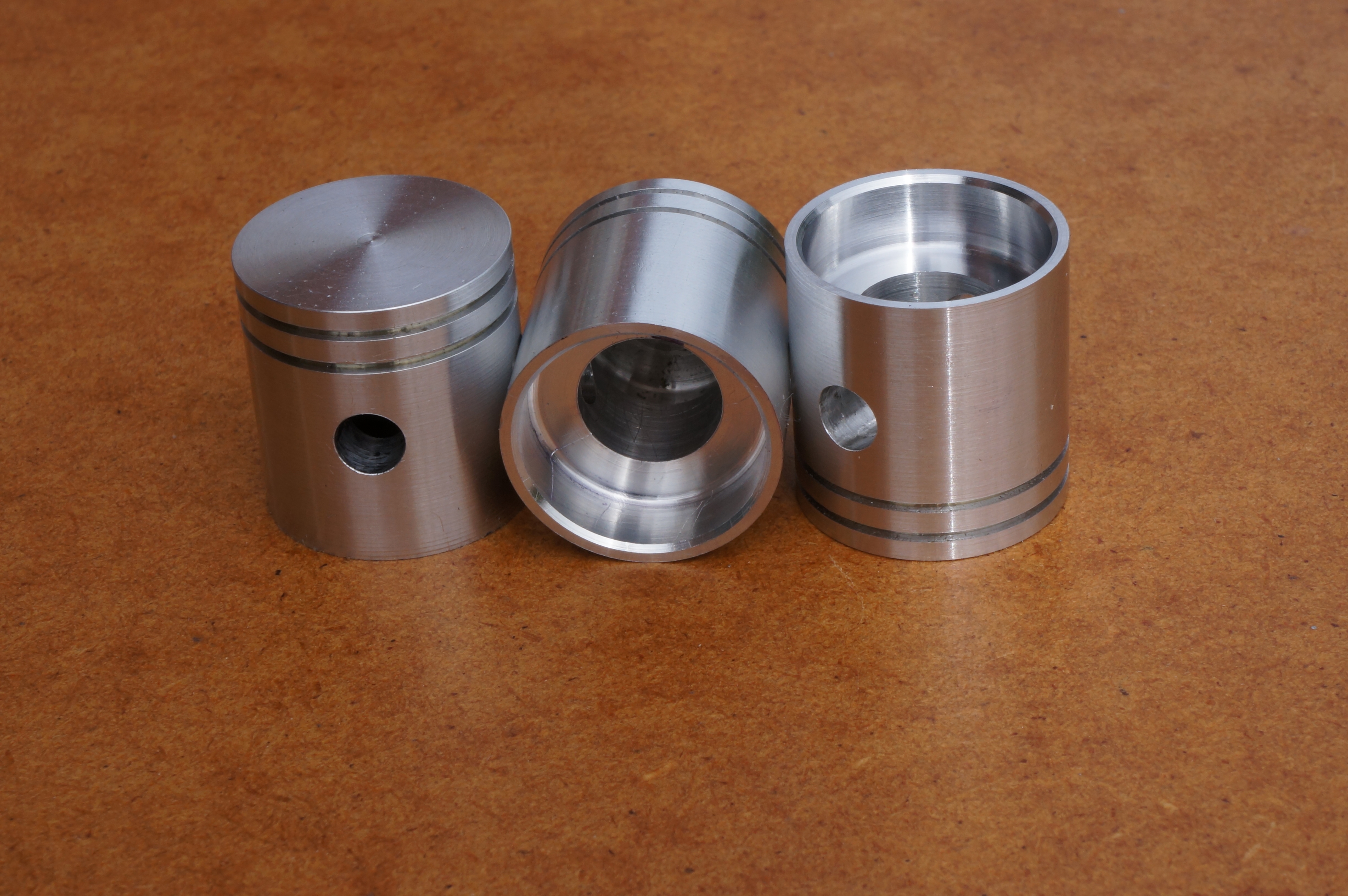
Pistons
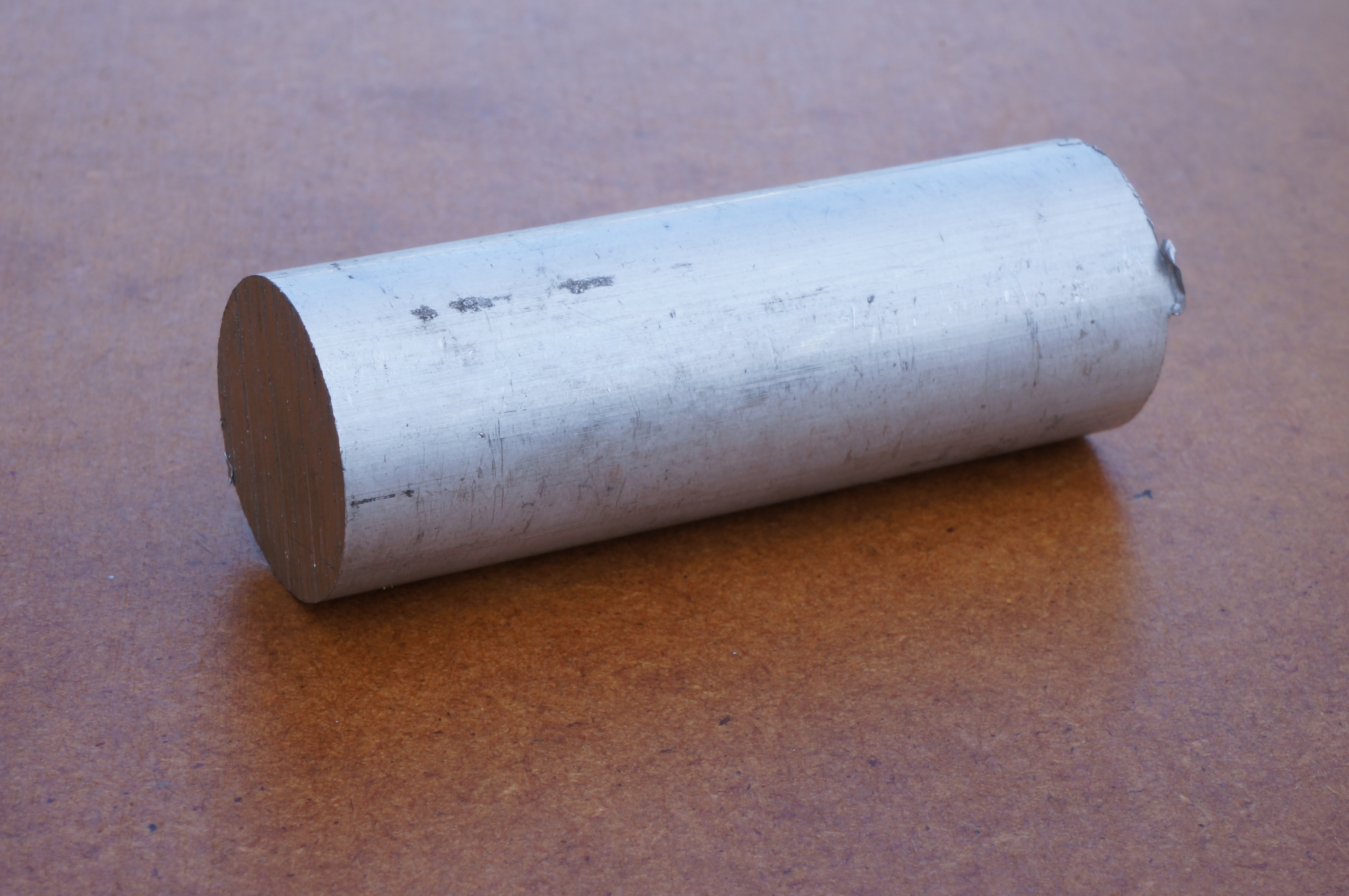
A piece of aluminium alloy bar, 7⁄8″ diameter by 2½″ long, is provided in the kit for making the pistons. Westbury suggests that if a high speed is not required, iron pistons may be a better bet. I will use the aluminium even though I am quite tempted by the advantages of iron. The drawings assume cast pistons and I will do some milling to emulate the cast shape. The most difficult thing would be to reproduce the circular bosses for the gudgeon pins. I am not going to try. I do not understand why there is a 1⁄32″ clearance each side of the little end. By reducing the distance between the boss faces from 7⁄16″ to 13⁄32″, the bearing area in the piston is increased by a round 15%. The pistons will otherwise be to the published drawing. The ring grooves are not specified, and will be made to fit the rings, after I have gapped them and lapped the faces.
I intend to make the gudgeon pins before boring the pistons, to get the right fit in the con-rods, then to make the pistons to suit. I want the pins considerably tighter in the pistons than in the little-end bush. Advice on the choice of material is conflicting; in the construction article Westbury calls for case hardened mild steel, Malcolm Stride suggests silver steel, unhardened, while Len Mason suggests silver steel "hardened right out". I think the latter would be taking too much of a risk for my liking, as they would be very brittle. The kit contains a piece of 3⁄16″ silver steel, but I think that will prove too sloppy in the reamed holes.
2015-01-17 – Checking the Piston Rings
Before I cut ring grooves in the pistons, I want to make sure the rings are OK. The first thing I find is that they will not fit in the bores which are dead size. I bored the left-over stub of iron liner material to make a gauge for the rings. At a diameter of 0.7543″ two of the rings had a 2 thou gap, and the other two, 4 thou. This means there is enough metal to give the rings a very light skim over the diameter. Done properly, this will result in a better fit and more uniform contact pressure than would be achieved by merely adjusting the gaps. The face width of the rings is about 0.028″, and I think they would benefit from lapping the faces. (1½ hours)
2015-02-07 – Tooling for the Piston Rings
I made a stub mandrel to hold the rings for skimming. This is turned so the ring gauge will just fit over, and has a shoulder the piston rings are clamped against by a central bolt and washer. The bolt is tightened while the rings are held by the ring gauge. This does not work as expected, with the rings jamming the sleeve when the clamp is tightened. (1¾ hours)
2015-02-10 – More messing with Piston Rings
Suspecting slight burrs on the rings, I gently rubbed the faces with light finger pressure on 800 grit paper, just removing some of the black surface layer. I also carefully rubbed them inside and out, and in the gap.
The rings now fit more easily into the sleeve, with measured gaps of 7, 7, 6, & 3 thou. I filed the smallest gap to 0.006″ for consistency. These gaps are really too big for the finished rings, so I need to make a slightly smaller closing sleeve, to reduce the circumference by 3 thou for a 3 thou gap. At 0.7533″ the stub mandrel is just the right size, but unfortunately it will have to come out of the chuck to make a new sleeve.
I made a new sleeve out of 1″ mild steel but I manage to get it too big again. Reading Tom Walshaw's article again, his recommended ring gap for a ¾″ bore is actually 2 thou. Even though the new closing sleeve is too big, if I try to clamp all four rings onto the mandrel while located with the sleeve, I still cannot get the sleeve off again. I will have to turn them one at a time. (2¾ hours)
2015-02-13 – Finishing the Piston Rings
First I re-machined the mandrel guide diameter to 0.7522″, making the seating a bit longer and faced back the outer shoulder, which does not really do anything anyway, to suit doing one ring at a time. Next I made another closing sleeve. At 0.7532″ bore, it was a bigger than I really wanted, but it will be OK. The rings still go very tight in it when clamped, a behaviour I don't really understand.
I set the mandrel up again, running true to 0.0002″ TIR. With the smallest-gapped ring I have to tighten the clamp plate fully after sliding the closing sleeve off. I set the topside (by eye on the degree scale) to 5.7° for 1:10 radial movement. I turned the first ring to 0.7497″, which I expected to be ideal. Irritatingly, however, when tried in No 1 cylinder, it shows a gap of 0.006″. In No 2 it is a little tighter, a 0.006 thou feeler will just go in the gap. This gap is bigger than intended but no disaster. The next one just cleaned up all round to 0.7510″. This gives a gap less than 0.002″, so it will need the gap easing a shade. Rings 3 & 4 were both turned to 0.7505″, and both accepted a 0.002″ feeler, No 3 quite tightly. After taking a tiny burr off ring No 2, its gap measured 2 thou in No 1 cylinder.
The rings are not dead flat on the faces. Using the cylinder bore gauge inside the ring closing sleeve, I had a means of holding the rings and applying even pressure. I rubbed one side of each ring flat on 800 grit paper on a surface plate. The least thickness I then measured was a little over 0.028″, so 28 thou is the target thickness. Using the first closing sleeve, I faced the back and, with a fresh sharp pointed tool cut a recess to hold a ring for lapping the second side to a set thickness. No 1 ring came out at 28–28½ thou thick, being thickest at the tips. With No 2 ring I started rubbing the side I had already done, but fortunately realised with enough metal to spare. This finished the same as No 1. Slightly worried about wear on the face of the holder, I carried on with No 3 ring, which indeed ended up a shade thinner at 0.0278–0.0283″. No 4 ring was again 0.0280–0.0285″ but this one was not thickest at the tips.
I think those will pass. I am hoping that the work put into the rings will help to ensure good compression from the outset, rapid bedding in, and long life. I put them back in the box, in numbered folds of paper. (5¼ hours)
2015-03-21 – Making tooling
As a final job today, I worked on filling a tool to bore the recess under the piston crowns. (1 hour)
2015-03-25 – Gudgeon pins
As it comes, the silver steel (US: drill rod) supplied in the kit for the gudgeon pins measures 0.1878″, ideal for polishing to nominal size. However, it is a bit too slack in my little ends and I will have to turn the pins. Trying pieces of mild steel as a gauge, I found 0.1882″ to be the target size.
Having a piece of mild steel the right size, I decided to try case-hardening it. Unfortunately Kasenit is no-longer available, and this was the first time I tried a substitute. The result was a pin that was as much as half a thou undersize after polishing, and a most unpleasant taint in the air of the workshop. The surface of the pin was file hard in places, but clearly just coating with the powder and heating for a couple of minutes is not going to be good enough. And next time I will do the job in the open air.
Turning a piece of silver steel, without tailstock support, I found it was springing out of the way a little, giving a taper, but also a good finish, which is often tricky on this stuff. With this I was at least able to confirm 0.1882″ as a fit, and 0.1881″ a running fit in the little ends.
At this point I made up a 3⁄16″ external lap, once I had found the piece of copper bar hiding in plain sight on the bench, that is. Using this I finally ended up with a 15⁄16″ length of silver steel, lapped to 0.1882″ diameter. After parting, I faced both ends to length, deburred rather than chamfered, drilled 2.2mm from both ends, then opened to 2.3mm and reamed 3⁄32″ through. (5¼ hours)
2015-03-26 – End Pads
I made an experimental end pad, turning the spigot to 0.094″ diameter, which is a tight push in one end of each gudgeon pin, but a bit loose in the other. I checked that there was sufficient clearance to spherical turn the end face of the pad after assembly, if the gudgeon pin is held in a drill chuck. (½ hour)
2015-03-27 – More End Pads
This morning I turned two end pads. I eased the spigots with 1200 grit paper to 0.0941″, which resulted in a light press in the larger ends of the gudgeon pins. With one pad in place in each pin I measured the lengths to determine how much to remove on finishing. I also decided, by fit in the little ends, which pin was which, but there was not much difference.
This afternoon I finished shaping the tool for the internal undercut in the pistons, and hardened and tempered it. I also reground a small parting tool blade for the piston ring grooves. It is a little over 0.024″ wide;
Later, I took a visitor unfamiliar with metalwork through turning two more end pads, getting him to do most of the work. (2¾ hours)
2015-03-28 – Finishing the Gudgeon Pins

After facing the parting pips off the pads, I pushed them in half way and pressed them home. With the first, it may have thrown a small burr on the brass pad which did not seem to press quite fully home, so for the other one I eased the edge of the hole in the pin with a scraper. Knowing which end of the pin was which, and using the measurements made yesterday, I spherical turned the first pads to length, then measured again to find out how much to take off each second pad. With one of them, I was only able to get sufficient friction to drive the very lightest cuts, though the pad still seemed a good fit and does not want to come out. I ended up with overall lengths of 0.741″ & 0.739″ leaving the pads about 0.005″ clear of the bore an each end.
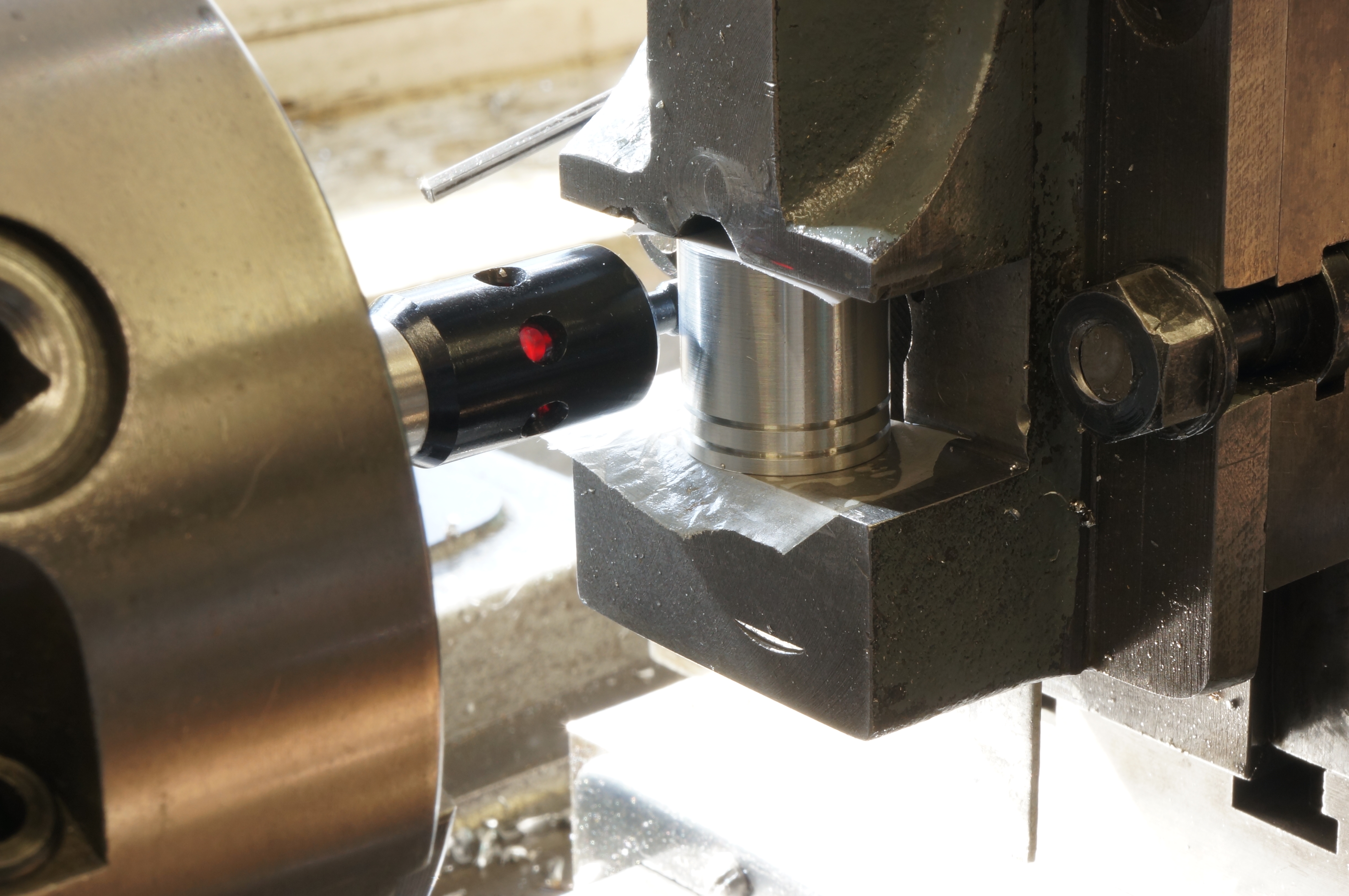
Making a start on the pistons, I did some experiments with different tool geometries to try to avoid stringy swarf. I found that whether the side rake was 6° or 24° stringy swarf was what I got. The finish from a fine cut was also pretty good either way. I opted for the high rake angle and a speed of 1500 rpm. I found I needed to withdraw the tool to avoid scoring a line along the piston when returning for another cut. I roughed the OD to 0.754″ then faced and centred, drilled 6.0mm to 0.690″ point depth, and opened with a 9.75mm drill. The first boring tool I tried was a bit long and squealed, so moved to an Eclipse boring tool. I completed the outer bore, down to the gudgeon pin bosses, and then bored the smaller diameter to depth. I finished it with a 3⁄8″ D-bit to 0.7225″ deep. The tool for undercutting, above the internal bosses, measured 0.085″ wide, and as the recess is to be 0.188″ axially, the depth down the hole goes from 0.619″ to 0.722″. The bore measures 0.392″ so for a finished diameter of 9⁄16″, the cut will need to be 0.085″ deep. (4¼ hours)
2015-03-31 – Turning the Pistons

I had made an allowance for the tricky internal undercut resulting in the depth not being quite right, which if left might result in the crown thickness being wrong. I faced the skirt, actually a thou too far, to an internal depth of 0.718″ and corrected the depth of the lower portion of the skirt. The exterior now showed a slight run-out, no more than a thou. I finish turned the the OD, at about 600 rpm, to 0.7490″ at the bottom, and 0.7491″ at the top, just where I wanted it.
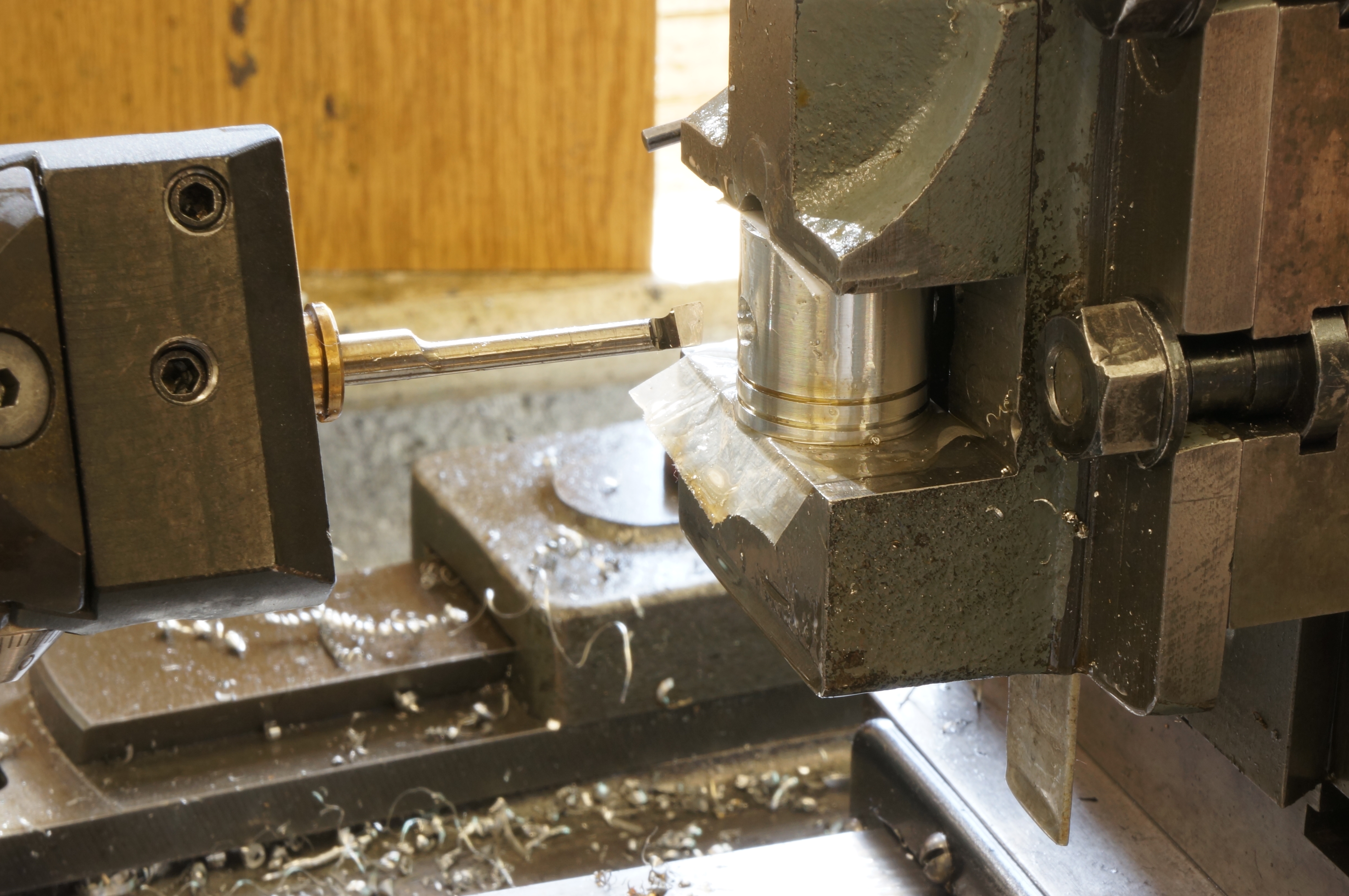
For the ring grooves, I used an 8mm square parting tool holder with the blade ground to a width a little less than the groove. The first cut, on the lower groove, seemed to be producing a slight taper, so I reground the tool with a tiny amount of side relief. It made a better job of the top groove, but I am not very happy with them. Quite a bit of deburring was needed to get the piston to go in the bore, and the sides of the grooves are not brilliant.
I re-made the grooving tool and turned the bar end for end in the chuck for the second piston. I roughed the diameter to 0.755″ and faced the end, centerd, drilled 6mm & 9.77mm and finished the interior to 0.718″ depth with the 3⁄8″ D-bit. I bored out the lower skirt, and the recess under the crown. Turning the outside, the finishing cut resulted in a diameter barely 0.0002″ larger than the first one, so I ran the tool down it again at the same setting. The result was bang-on: 0.7490″ at the bottom, 0.7491″ at the top. The new grooving tool worked much better, but I was surprised when a second, one thou, cut on the side of the groove allowed allowed a piston ring to fit nicely. I had misread the mic, and the width of the blade was 0.028″, not the 0.023″ I thought I had made it. A lucky escape, and a good groove. The second one came out very nicely too. (5 hours)
2015-04-01 – Making an extra one
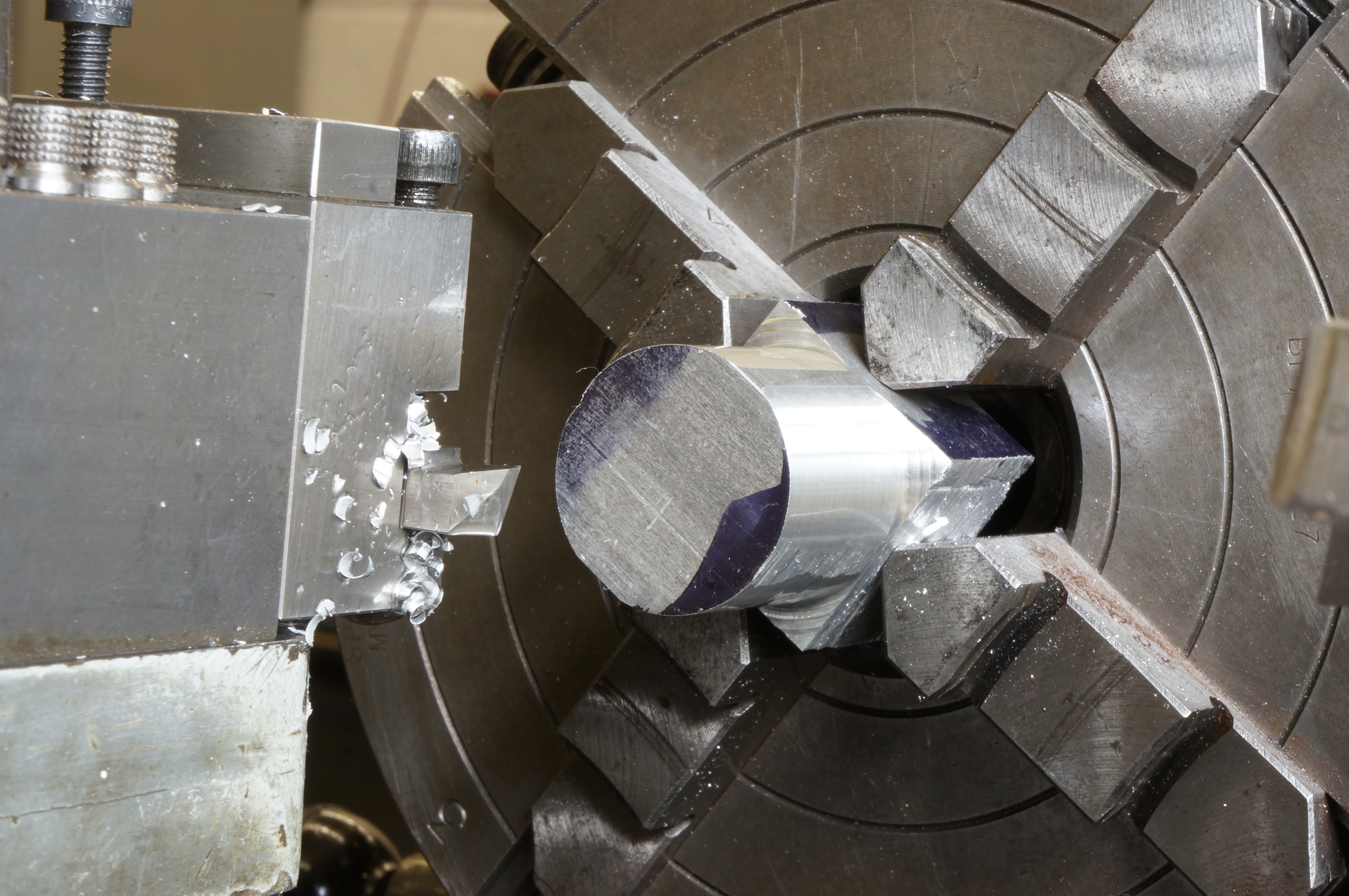
Although the first pair of ring grooves were not too bad, I was not really satisfied and knew I could do much better. The bar provided in the kit is HE30, and I had some suitable rectangular stock so I decided to make another piston. I sawed off a piece an inch square and 1¾″ long, stuck it in the 4-jaw and turned about an inch length to 7⁄8″ diameter, then gripped by that diameter in the 3-jaw to turn up the piston exactly as before. Compensating for boring 2 thou too deep, in order to preserve the correct crown thickness, means that the internal undercut makes the gudgeon pin bosses short by the same amount (though not actually measured). Finishing the OD again required a cut of a bit less than 0.001″, and a second pass. In cutting the ring grooves, at 200 rpm, I found with this one I needed a shave of half a thou, or a little more, to get the ends of the the test ring to bottom in the groove. (2¾ hours)
2015-04-04 – Parting and facing to length
I started by making a block of HE30 for experimental gudgeon pin holes. Then I had a think about how to set the pistons up for making the holes, and decided they needed to be parted, as gripping by the chucking pieces did not seem the right method. I parted the pistons off and rough faced them, leaving about 0.010″ to finish to length. I then measured each one and faced them to length, or more precisely, they turned out about a 0.001″ short in each case.
While using the top face as a datum for the gudgeon pin bore would ensure all the piston crowns would be in exactly the same position at top dead, they did not seem to be precisely square. The bottom of the skirt, being machined at the same setting as the OD, would be more likely to be accurately square, and getting the gudgeon pin hole square is more important than a sub-thousandth variation in height. The one thou average shortness can be accounted for in setting up.
I faced the left-over piston chucking pieces to use for gudgeon pin hole diameter target practice, and milled a slab of light alloy for a jig to hold the pistons for milling their interiors to form the internal bosses. (4¼ hours)
2015-04-05 – Experimenting with gudgeon pin holes
This morning I bored the jig for the piston and drilled & tapped the hole for the clamp bolt.
After lunch I set up for boring the pistons, on the vertical slide and vice in the lathe, as I know the fixed jaw of the vice will be square to the spindle. I worked on a trial hole. I have three 3⁄16″ hand reamers to choose from, and I want to find out how to get the best fit, and at this size a tenth of a thou makes a difference. I set up one of the test pieces, centred it and drilled 4.5mm, to find the freshly ground drill is cutting about 0.006″ over size. I ground a boring tool and ran that through in the boring head to ensure the hole was true. First I tried my oldest reamer, which has spiral flutes and has been doctored and now cuts a bit smaller than I intended it to (No 1). Putting this through at 700 rpm with RTD lubricant gave a hole that was too small. I tried the new straight flute reamer, the one I used for a final shave on the con-rods, through the hole and this made the hole too big, as expected (No 3). The newest reamer also has a spiral, which I prefer. This fits in the hole more easily, so I will try that next (No 2).
I made a fresh hole, reamed with No 1, then No 2. No 2 reamer does not reach full diameter until it is nearly all the way through, which cannot be done while it in the vice, so the piece had to be removed and the reamer put through by hand to finish the hole. The result was a bit odd. Perhaps this new reamer needs to be put through a few more holes to run it in. (4¾ hours)
2015-04-12 – Boring a piston
Ideally, the gudgeon pin wants to be a tight enough fit in the piston to not rotate even when the parts are hot. This may throw some light on the required fit. Heating the alloy to 100°C would, according to my calculation, expand the pin hole by 0.0004″. I tried a hole made with No 1 reamer only, again finished by hand. This allowed a 0.1877″ test pin to just enter, and when the piece is taken out of boiling water the 0.1881″ test pin will just, just enter the hole. But these little piston are not going to stay hot long enough to do even a frantic assembly, which would be the last thing to do anyway. Hot is not going to be the way.
With a couple more trials, I found that using No 1 and 2 reamers in the lathe, at 350 rpm, pecking the cut 1⁄8″ at a time, then putting No 2 and 3 reamers through gently by hand, produced exactly the tight push fit I wanted.
Finally, I set up a piston, the one with the dodgy ring grooves, remembering its 0.749″ diameter but forgetting to put it skirt down. I lined it up with the electric probe, as providing the lightest touch, and centred, drilled 4.3 & 4.5 mm, bored (twice at the same setting) and reamed the hole, then removed the piston for finish reaming by hand. After cleaning up, the fit is good. (3½ hours)
2015-04-14 – Boring another piston
Today I bored the gudgeon pin hole in the second piston. (¾ hour)
2015-04-17 – Milling
The first job today was boring the last of the pistons.
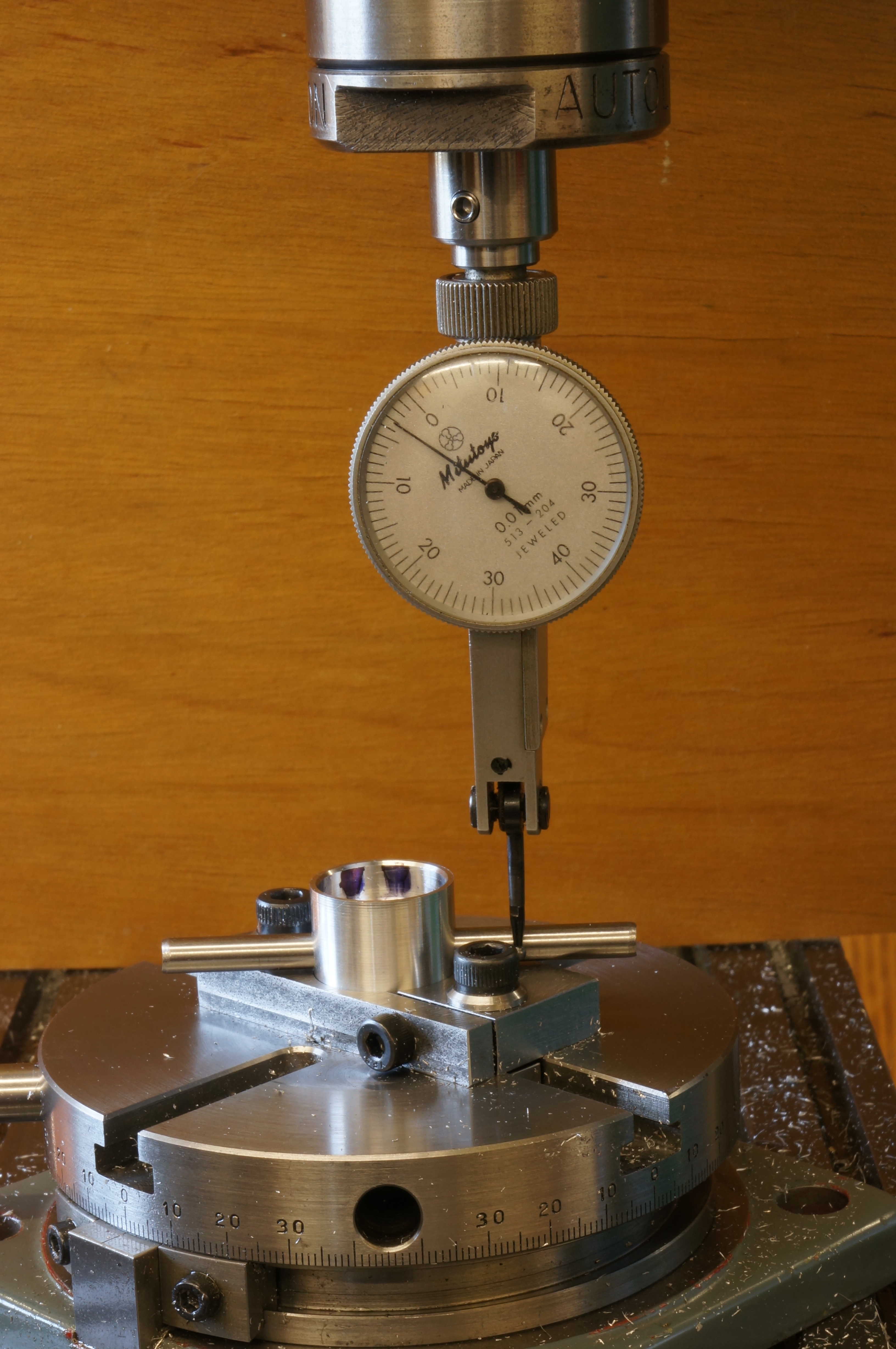
The next job was slitting the piston milling jig to make a clamp. With the jig completed, I could set up for milling the internal bosses. The set up for this is a bit complicated. First, I clocked the central hole of the rotary table dead under the spindle and zeroed the table dials. Next, I clamped a piston in the jig, and adjusted the position of the jig to get the piston concentric with the rotary table. These settings are fixed for the rest of the job. Finally, I used a 3⁄16″ ground rod in the gudgeon pin hole to set it parallel to the table. With the angle read off from the rotary table (in this instance it was 3.2° clockwise) the rotary table stops could be set for the nominal 38.8° swing each way (at 42° clockwise and 35.6° anticlock) required.
The swing angle produces the correct boss geometry when used with a 1⁄8″ cutter, in this case a ball-nosed slot drill. A long-series one was needed to reach 9⁄16″ into the piston. With the Y-axis on centre, the tool can be fed radially with the X-axis to put on the cut for each pass made by rotating the table between the stops. All being well, at a dial reading of 0.265″ the cut should coincide with the internal diameter of the skirt.
With both arcs milled, I set the table back at the zero position (3.2° for this one), fed the tool in an extra 0.050″, and milled flat the inside faces of the bosses at a single pass each side. The finish on these faces was not brilliant but they do nothing anyway. I found it difficult to deburr the inside without making scratches. (3¾ hours)
2015-04-18 – More milling
This morning I milled the second piston. While setting up, I discovered that locking the milling machine's quill moves it a noticeable amount, so setting up needs to be done with the quill clamped or free according to the state it will be in when machining. For deburring this one I used an oak 'matchstick' to fold the burrs back and forth until they broke off.
In the afternoon I milled the third one. This time I milled the arcs at top speed of 3750 rpm, but reverted to 2250 for the boss faces.
After deburring this one, and a bit more work on the others, that is the pistons done. (4½ hours)
2015-04-25 – Trial fitting
The gudgeon pins are a tight enough fit in the pistons to be too hard to comfortably push in by hand. I sat the pistons in a v-block and pushed the well oiled pins in with a rod in the drilling machine chuck.
I did a trial assembly with the crankshaft and cylinders in place, but no piston rings. Everything moves smoothly without detectable binding, but there was a little discolouration of the oil showing on top of No 2 piston, towards the flywheel. Turning the piston round shows the same pattern, so any misalignment is in the little end, not the piston. I don't think it will be a problem.
If possible, I intend to leave the piston—con-rod assemblies together, as pushing the gudgeon pins in and out is bound to loosen the fit. The milling machine was covered in fine, clingy aluminium swarf, as I had to use the air gun to clear the pistons between cuts. After cleaning the lathe and milling machine down, I moved on to the tappets. (2 hours)