
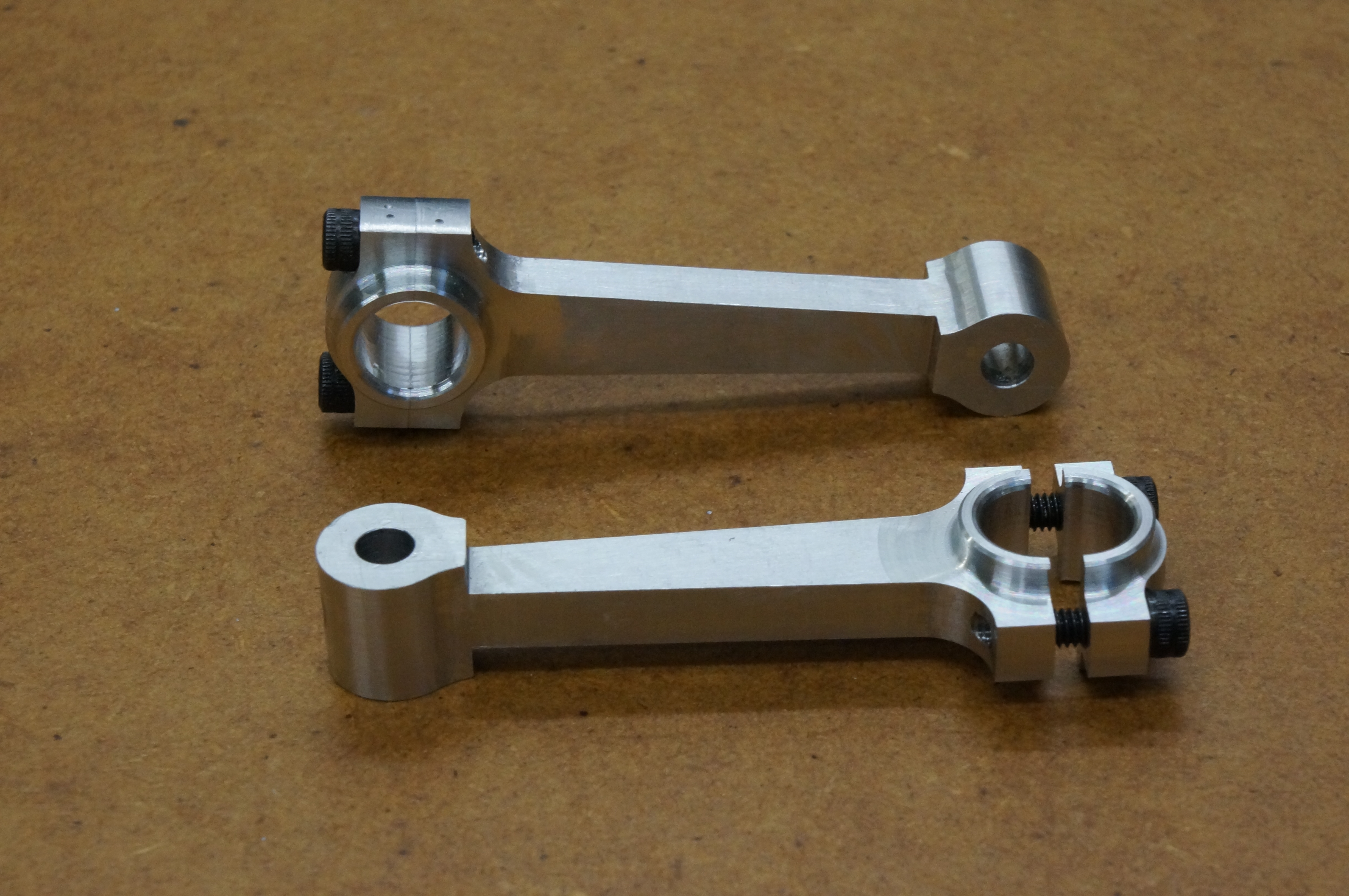
Connecting Rods
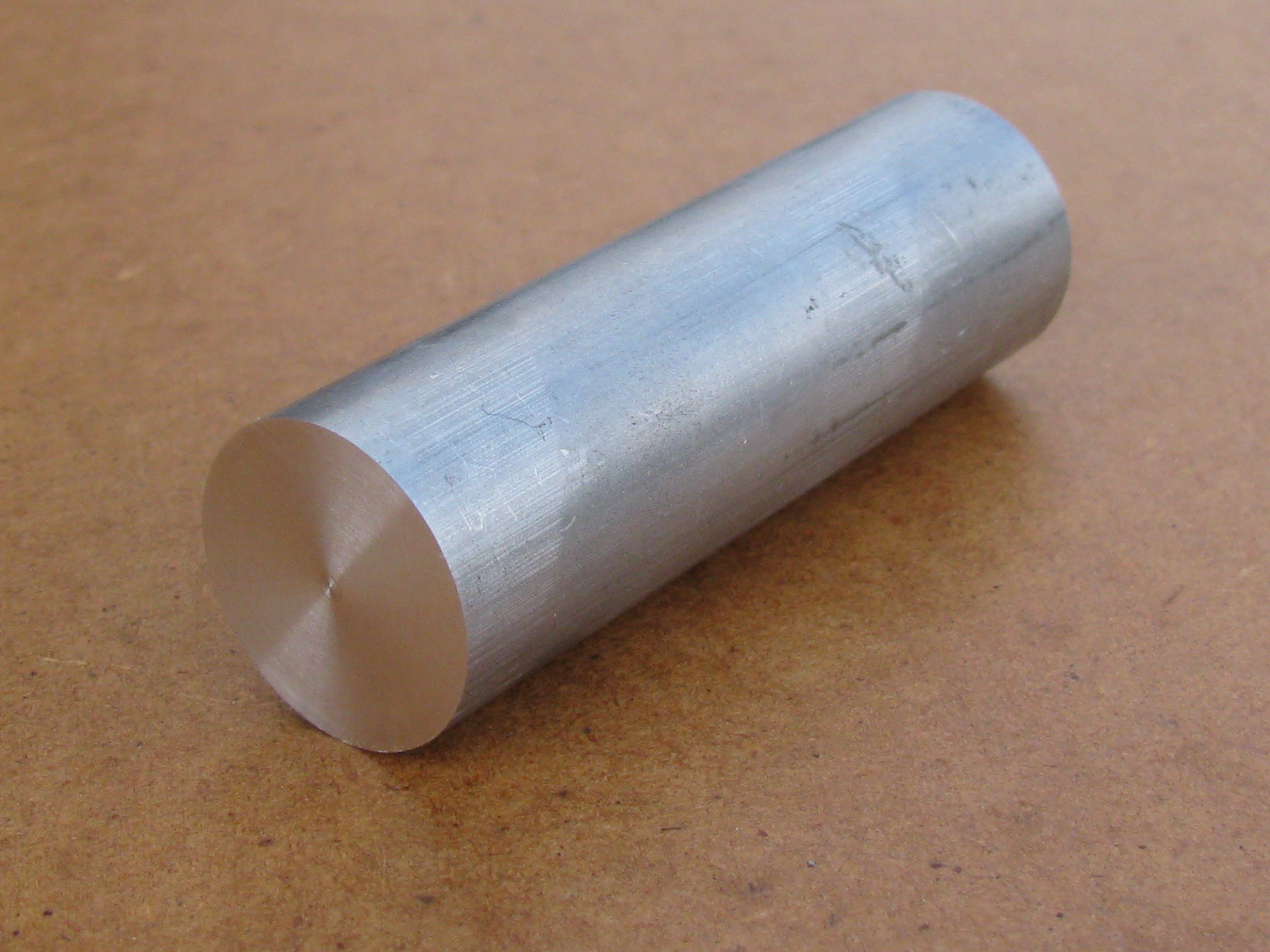
A piece of ¾″ alloy (2014A) bar is provided in the kit for these. The drawings assume a bronze casting will be available and are therefore rather uninformative and some of the dimensions that are given do not correspond with the drawing anyway. The original article shows 8BA big-end bolts while the drawing sheets show 6-BA. I have gone for 6-BA cap-heads. I have drawn my rods up as a flat profile 3⁄16″ thick with bosses projecting each side of 1⁄16″ wall thickness. The flanks of the profile are tangential to the pins, and I have used a ruling 3⁄16″ radius except at the big end cap. I have reduced the centres of the big-end bolts to ½″ and reduced the turned OD of the big end lugs by 1⁄32″ while making the bolting lugs 1⁄16″ longer to provide more thread length and thickness under the bolt heads. Westbury and Mason both suggest that fluting the rod to I-section is not necessary with Dural. Calculation shows that fluting would save about 12% of the total rod mass (including bolts). In any case the alloy rods will be far lighter than bronze ones, and I don't want to run this engine at high revs, so I am not going for fluting.
2012-03-10 - Making a round bar flat
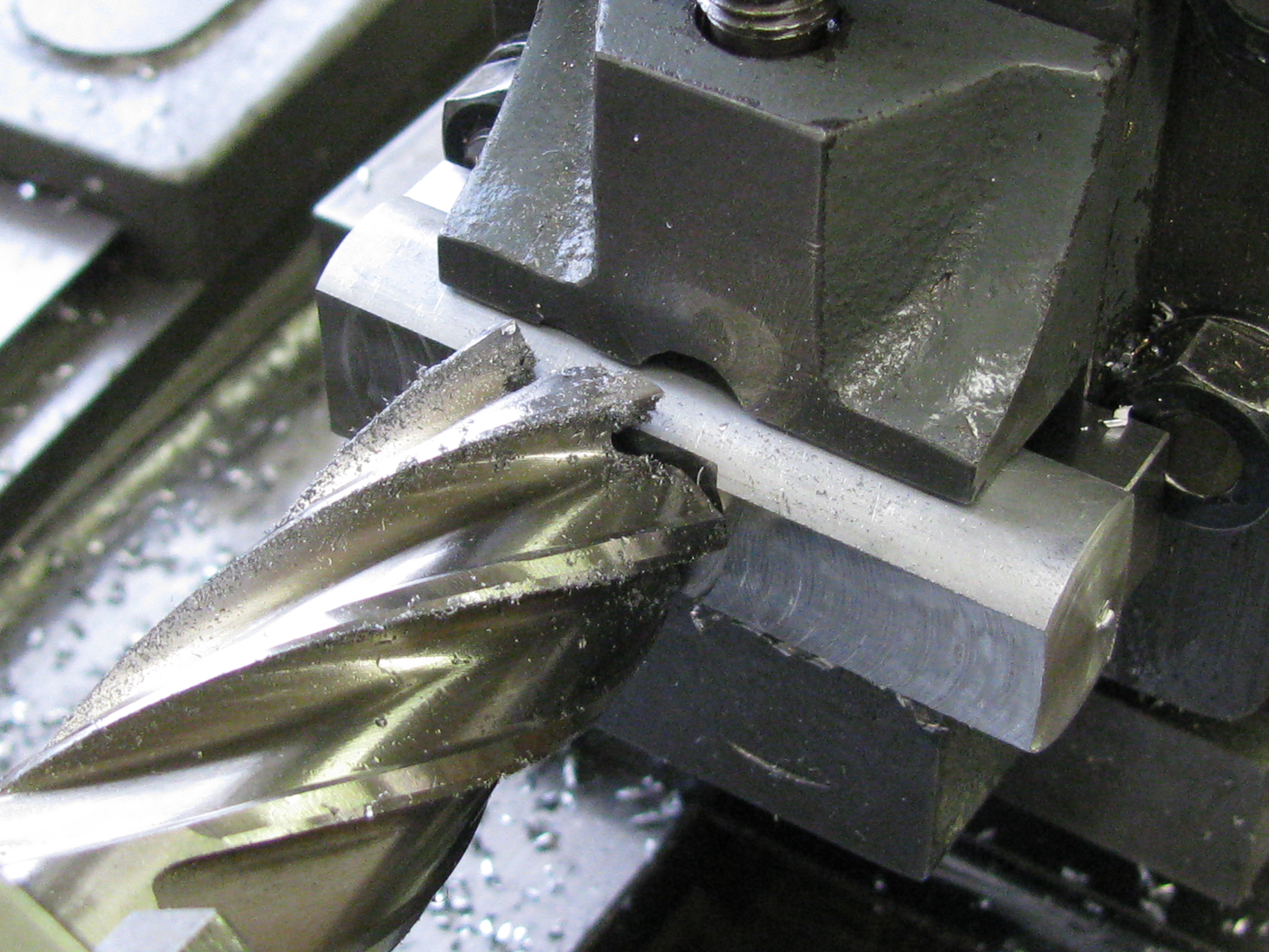
I parted off two 23⁄8″ lengths from the bar provided, leaving a 15⁄8″ piece for other jobs. The parted faces were well off flat and I evidently need to sharpen the parting blade. After facing one end of each I changed over to milling mode and mounted the rods in the vice on the vertical slide for milling the flat sides. I took good care to bed against the packers to get parallel sides, and used a 25mm end mill, in the three-jaw chuck to mill to what turned out to be about 14 thou over the finished 3⁄8″ thickness. It is risky using and end-mill in a 3-jaw as it can creep out of the chuck, unnoticed until too late. But my collet chuck is not big enough and anyway the alloy does not impose high cutting loads and it turned out fine. I drilled and reamed ¼″ holes as close to centre as I could get, and 0.260″ from the faced end, allowing ten thou for milling the cap profile. (3½ hours)
2012-03-11 - Starting the cap profiles
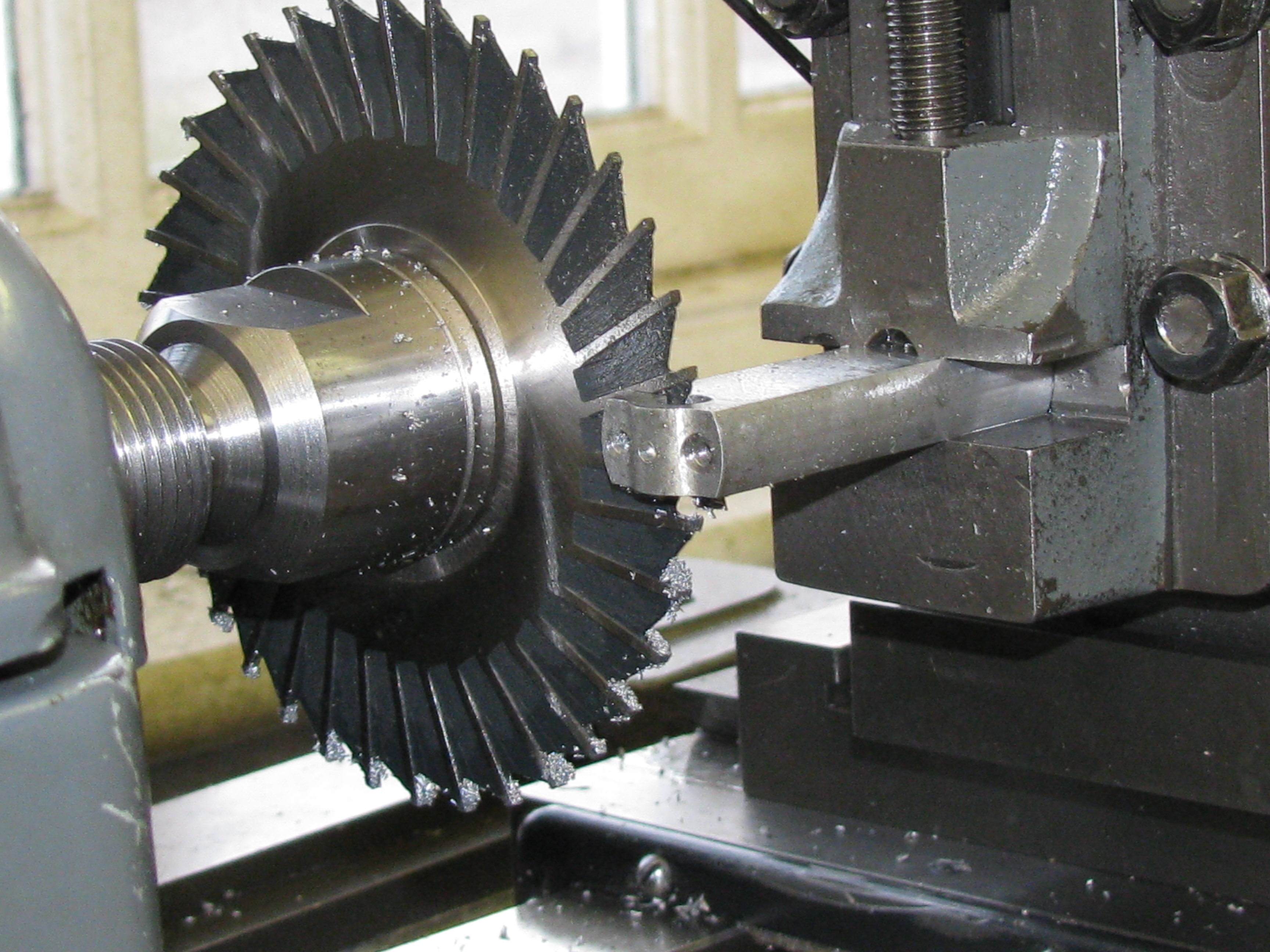
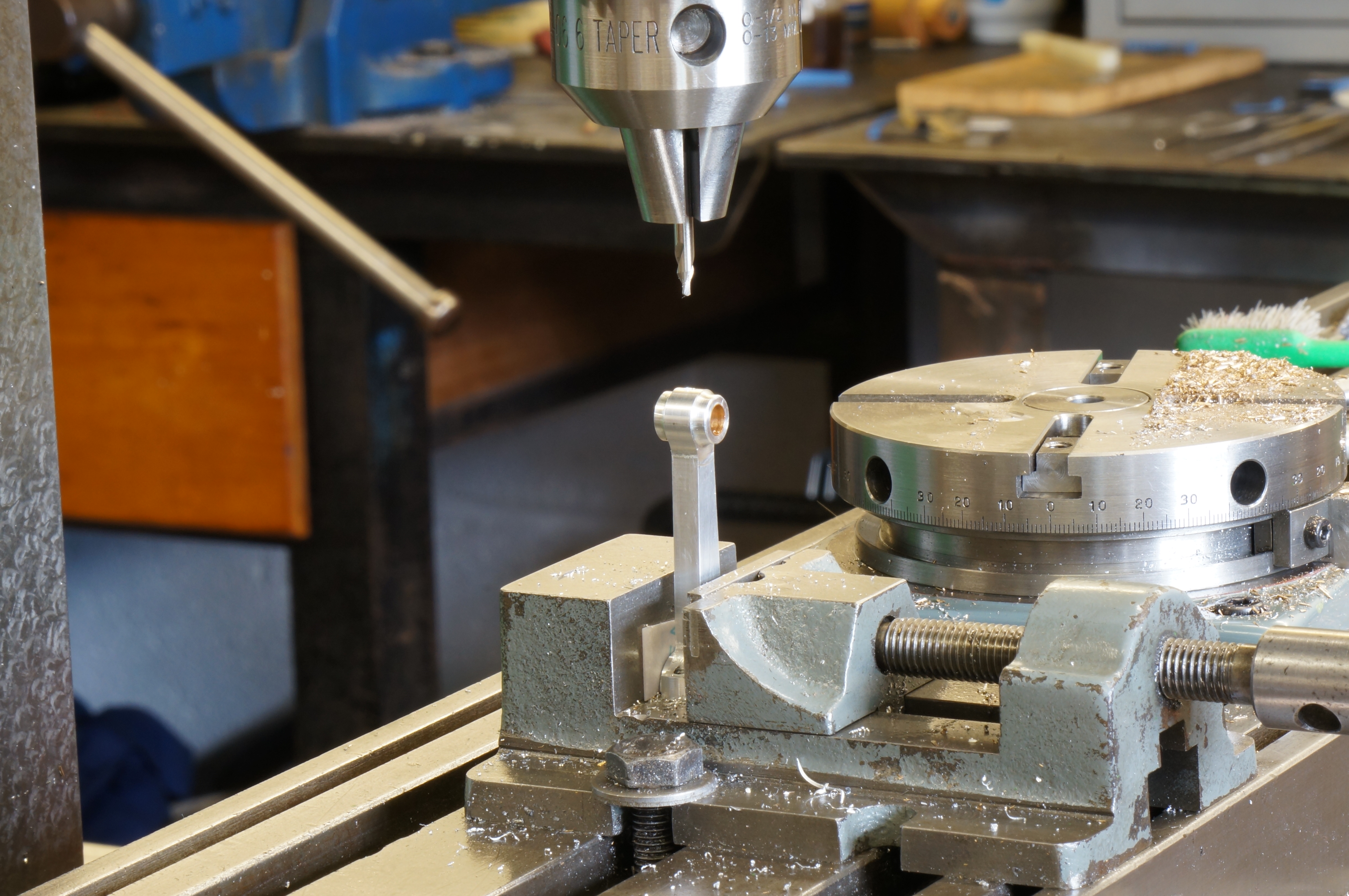
Armed with dimensions worked out on the drawing I started profiling the big end caps by milling scallops each side. This needs doing first because the parts would be well-nigh impossible to hold for profiling once separated from the rod.
Very useful for any milling work is an LED edge-finder. I have one, but with an aluminium body that is not concentric with the probe. I would not recommend this type. As I knew I would want it repeatedly for this job I set it running true in the Griptru chuck and put the milling cutter in the collet chuck so swapping between the two was simply a matter of swapping chucks. This takes little more time than changing ER collets. Adding and subtracting dial readings, and remembering backlash directions requires concentration, and while DRO's would be nice, it does keep a part of the mind exercised. The results were pretty accurate, anyway.
With the scallops done, I started setting up the small rotary table to mill the radius. (2¾ hours)
2012-03-24 - More work on big end caps
The first job was milling the radii on the caps. While they are pretty good, the radii do not blend perfectly off the machine, so a bit of hand finishing, with fine paper wrapped round a needle file, was done while there is plenty of bar to hold onto.
The next set-up involved mounting the rods end-on for drilling and sawing the caps off.
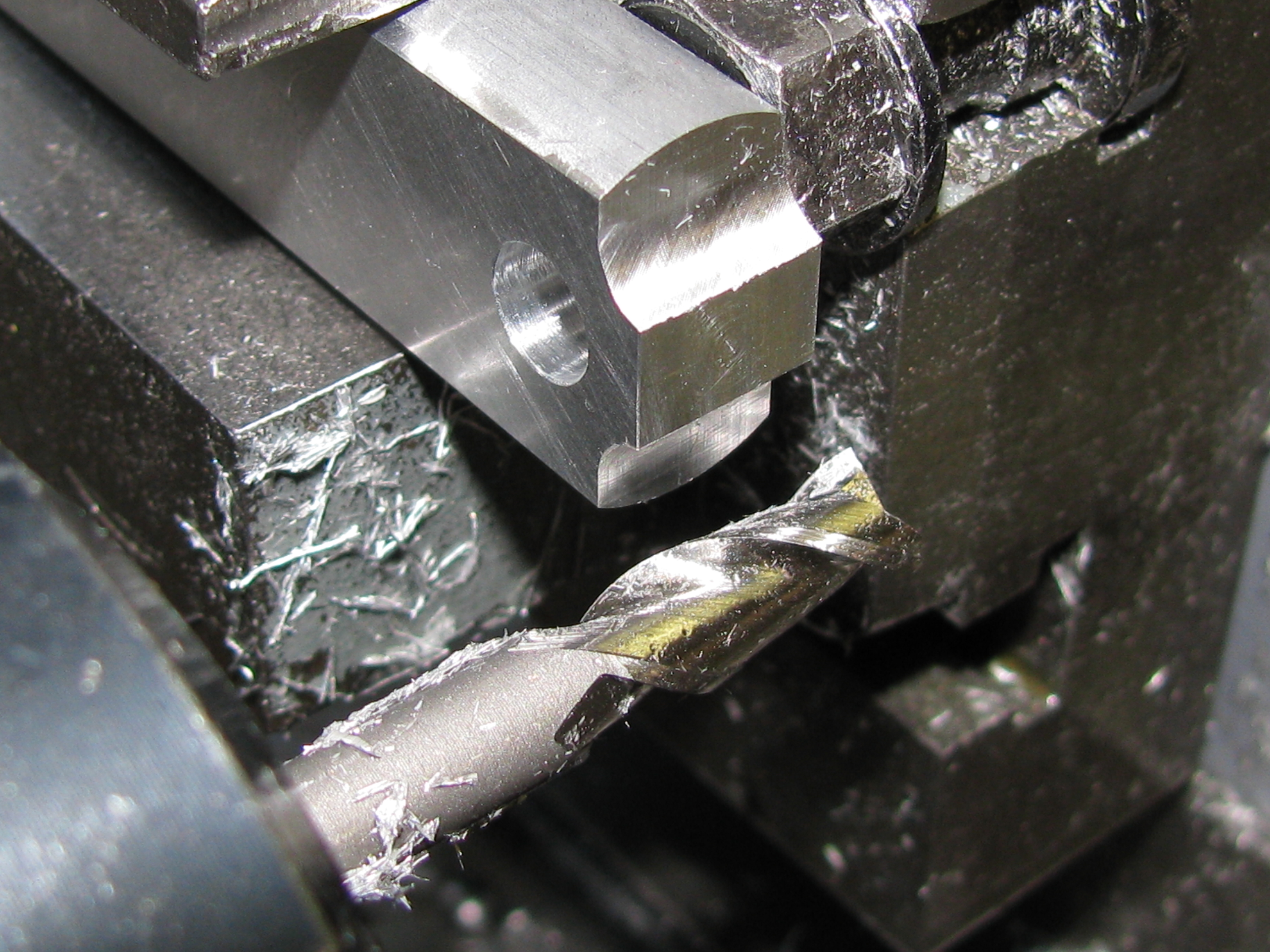
Despite the projection, the top face of the first one clocked up level when the vice was pulled up tight. I drilled the 1⁄16″ oil hole and opened it out to 3⁄32″ diameter for 5⁄64″ depth to take an oil scoop which will be loctited in. I carefully drilled and tapped the bolt holes and milled seating pockets for the cap-head bolts with a 3⁄16″ slot drill, just deep enough to touch full circle.
I cut the cap off with a 1⁄16″ slitting saw, leaving about 20 thou for finishing the bolting face, and took rod out of the vice forgetting to mill the sawn face flat. (5 hours)
2012-04-07 - Finishing the caps
Among other bits and pieces, some new end mills arrived today. I finally got round to sticking some blind holes in an off-cut of 1″ MDF to make a storage block for all my imperial size cutters. This is much better for any cutting tools than having them rattling around in a box.
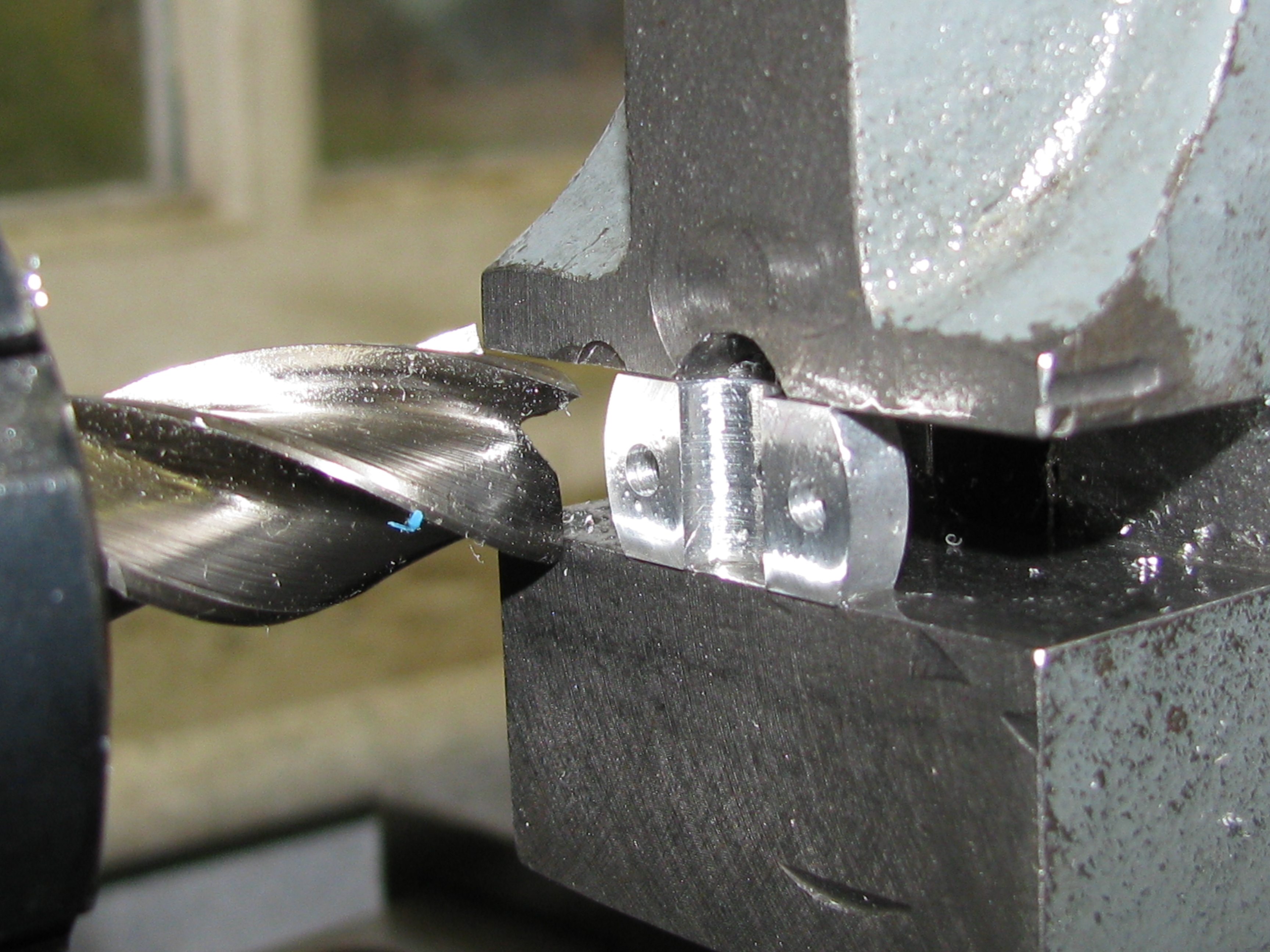
Setting the second con-rod level for drilling and slitting unaccountably proved more troublesome than the first but in the end I got it right to about a thou over the length. I drilled, tapped and slit it as before, and then took about 5 thou off the end of the rod with a new end mill and very lightly counterbored the tapped holes to prevent burrs lifting when the bolts are tightened. I re-mounted the first rod and faced that end too.
Machining the sawn faces of the end caps presented a bit of problem with lining them up. I could have tried packers behind the lugs on each side, but this would have been pretty fiddly. A bit of investigation with a micrometer showed that the sawn faces were actually pretty accurate, so I decided to work from them. I put a stub of previously finely faced bar in the 3-jaw and checked the face was running true. I used this to push the cap into the lightly tightened vice to leave just enough projecting for milling to size. Both caps were done this way. The machined surfaces blue up nicely and will not need lapping. Under the right conditions, milling can give a flatter face than facing in the lathe, because lathes are normally set to face very slightly concave. (4 hours)
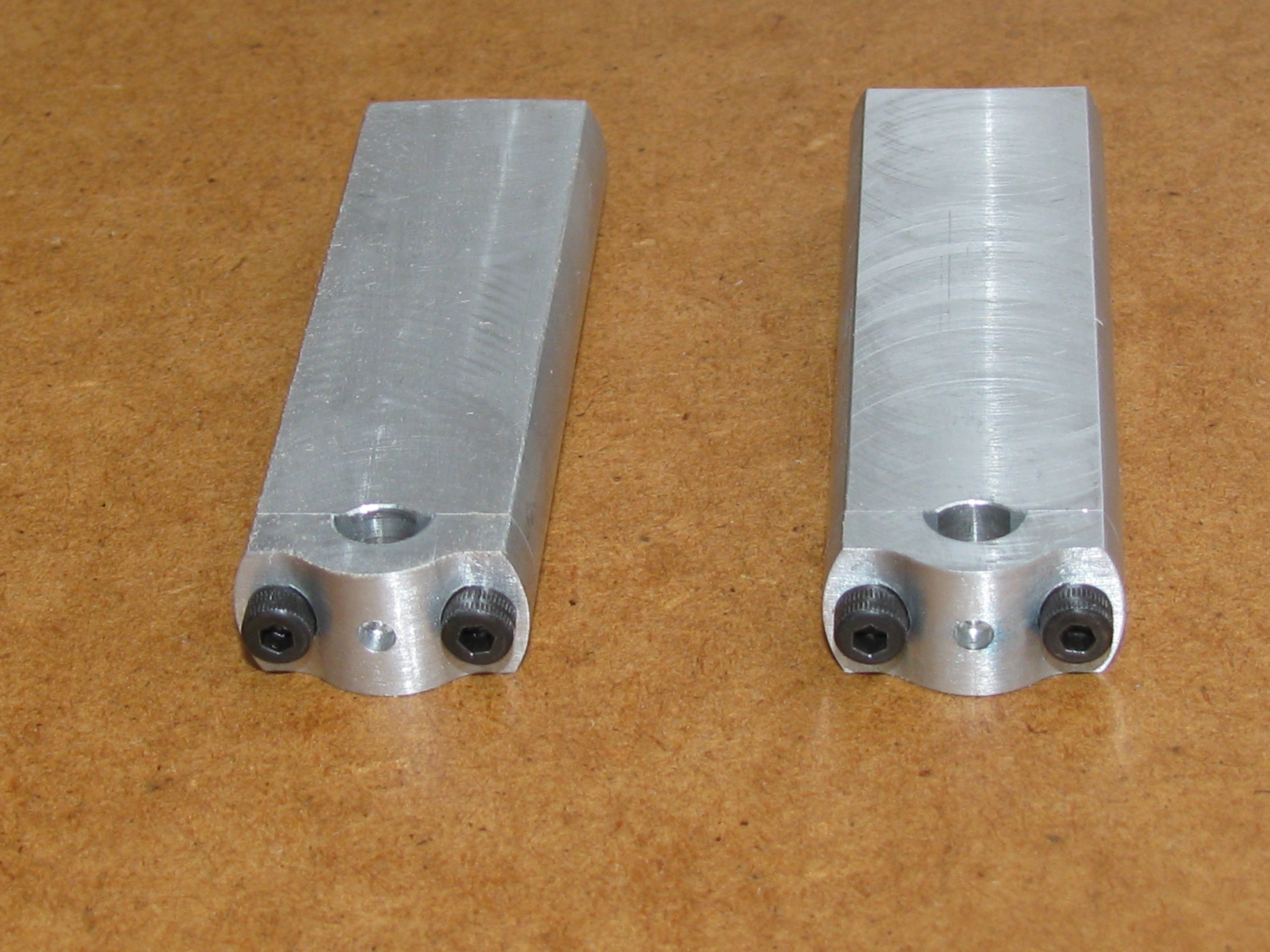
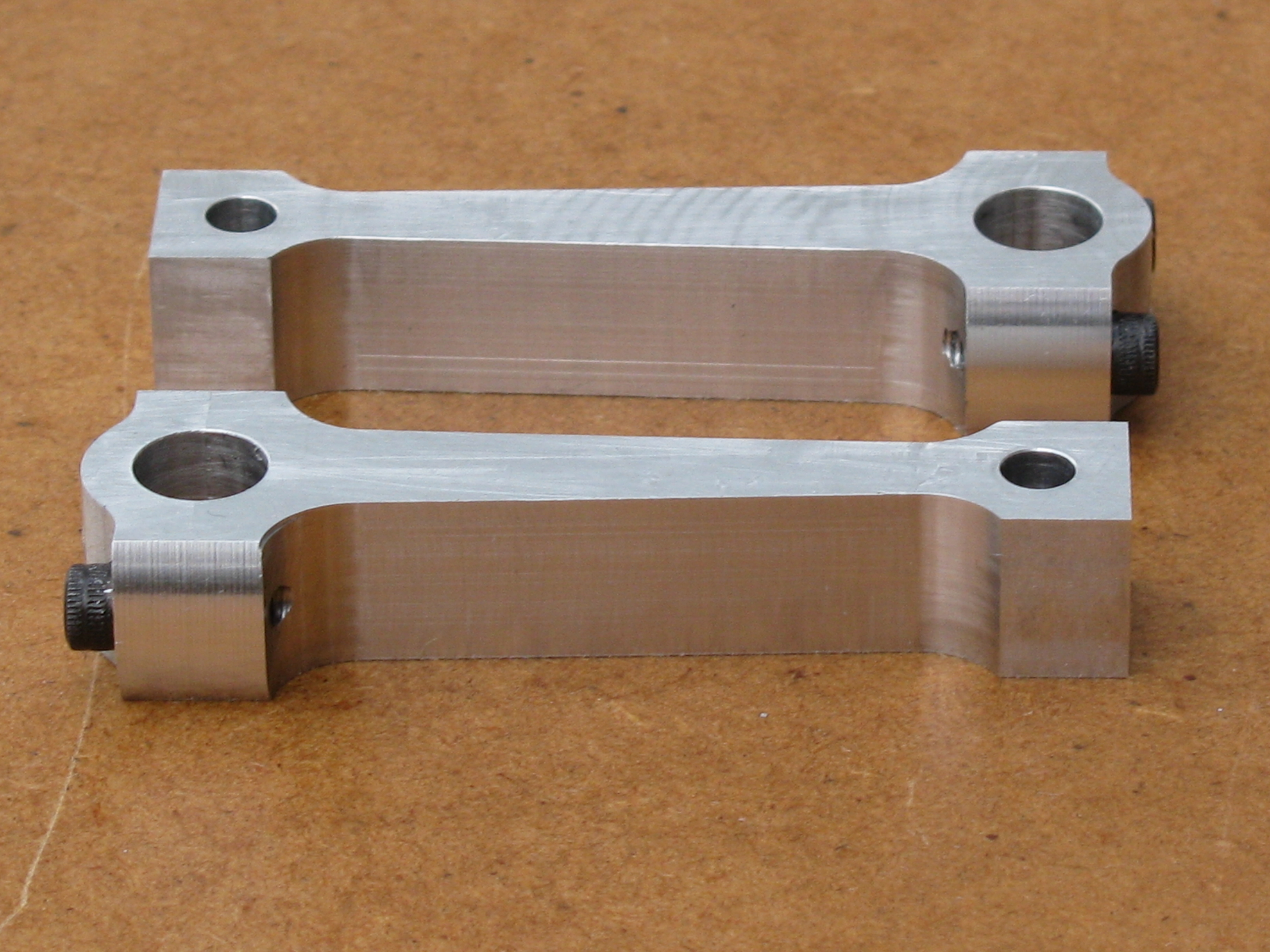
With the parts cleaned up I assembled the caps on the rods, aligning them carefully and bolting up firmly. They will stay there without being moved for most of the rest of the machining.
.
2012-04-09 - Boring and preparing for milling the profiles
With the caps made, the next job was to re-bore the big ends. Not to finished size yet, as there is still more than three quarters of the aluminium to be removed, and this may result in some distortion. The little ends can have preliminary holes in too, to aid setting up for milling the profiles. Boring to final size will be just about the last job to be done. By making both holes 1⁄32″ under finished size, a bolt through each can be used for setting the correct taper for the flanks. The 5⁄32″ little end hole will be just right for holding with an M4 bolt.
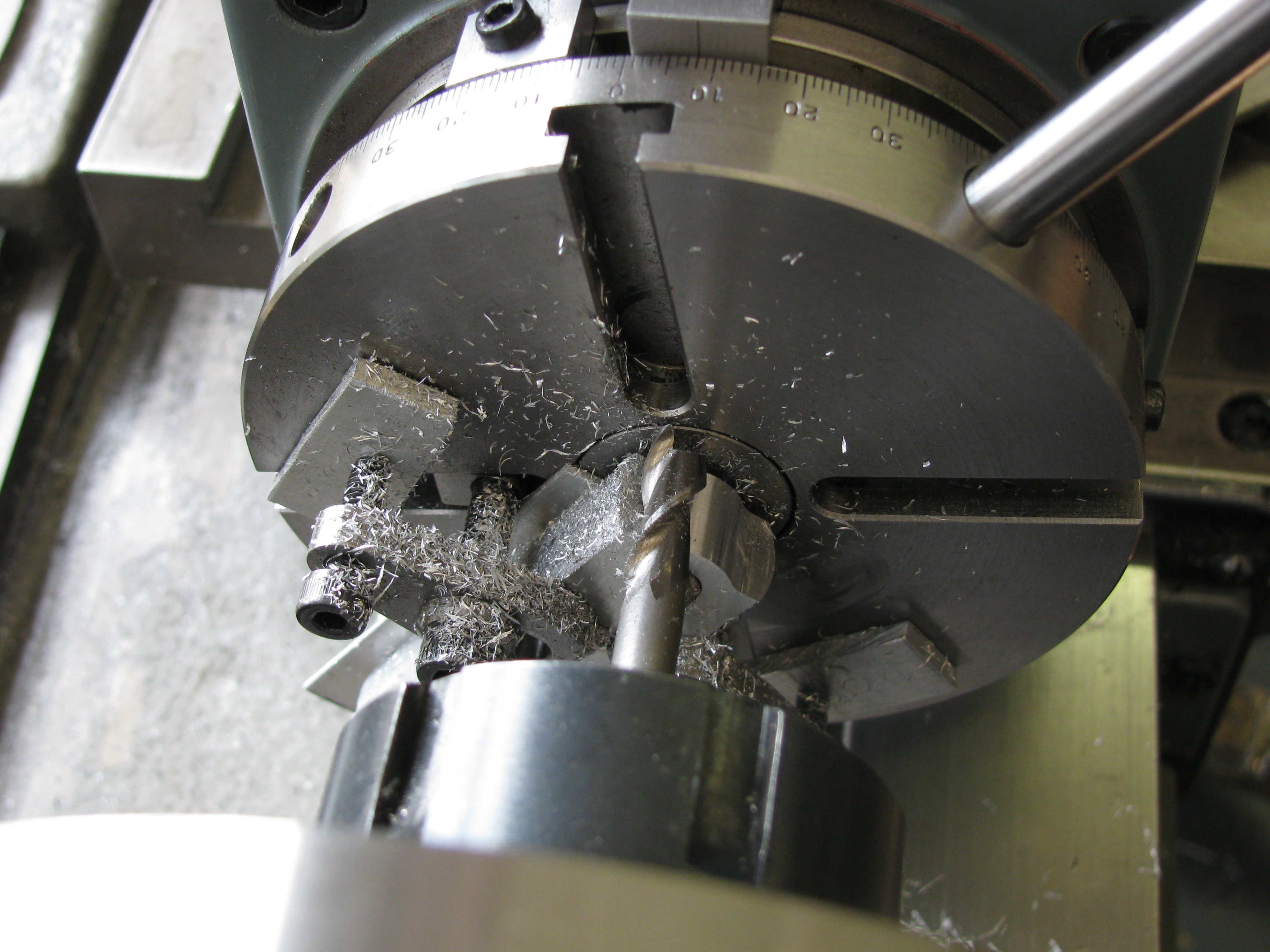
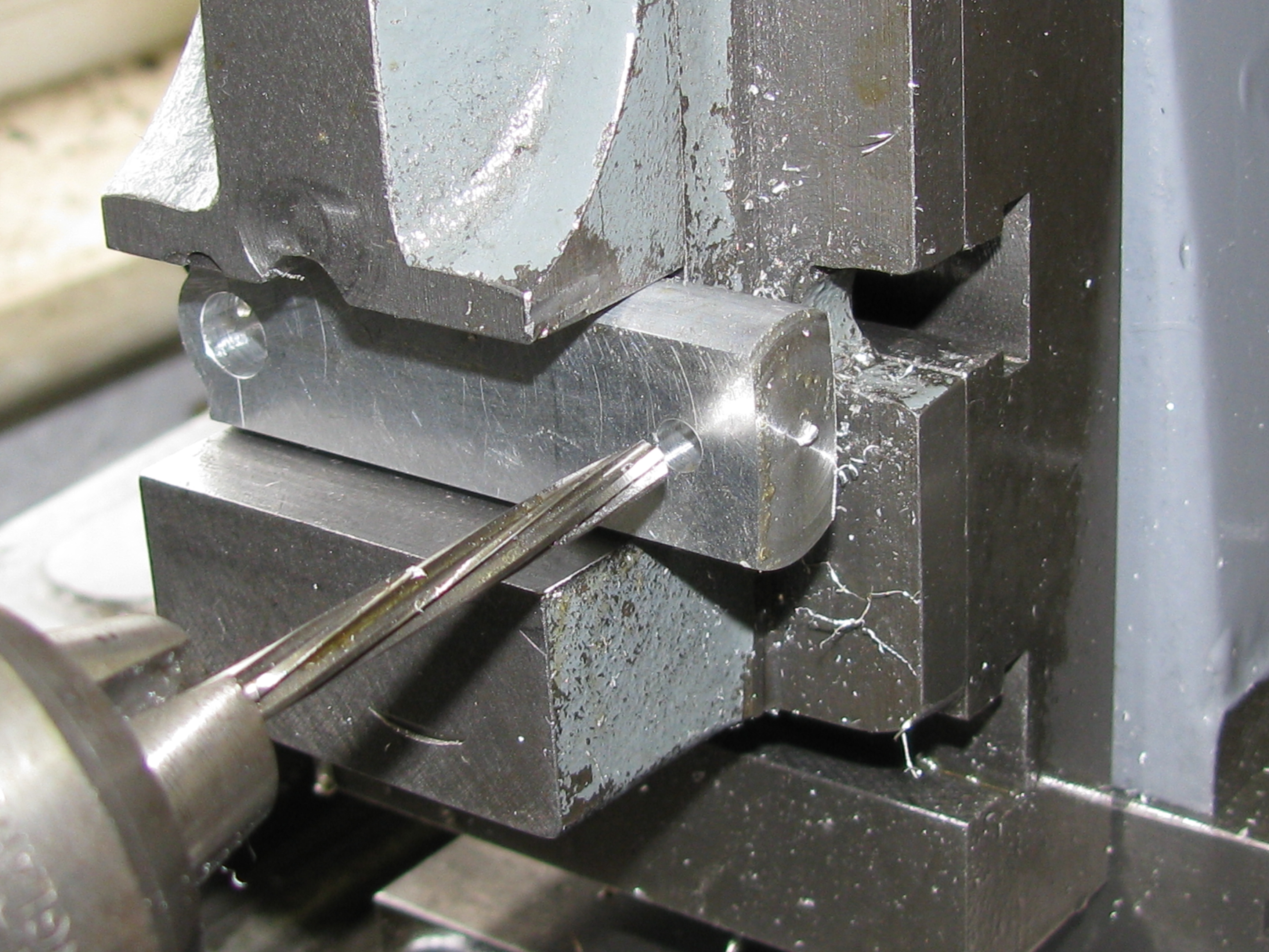
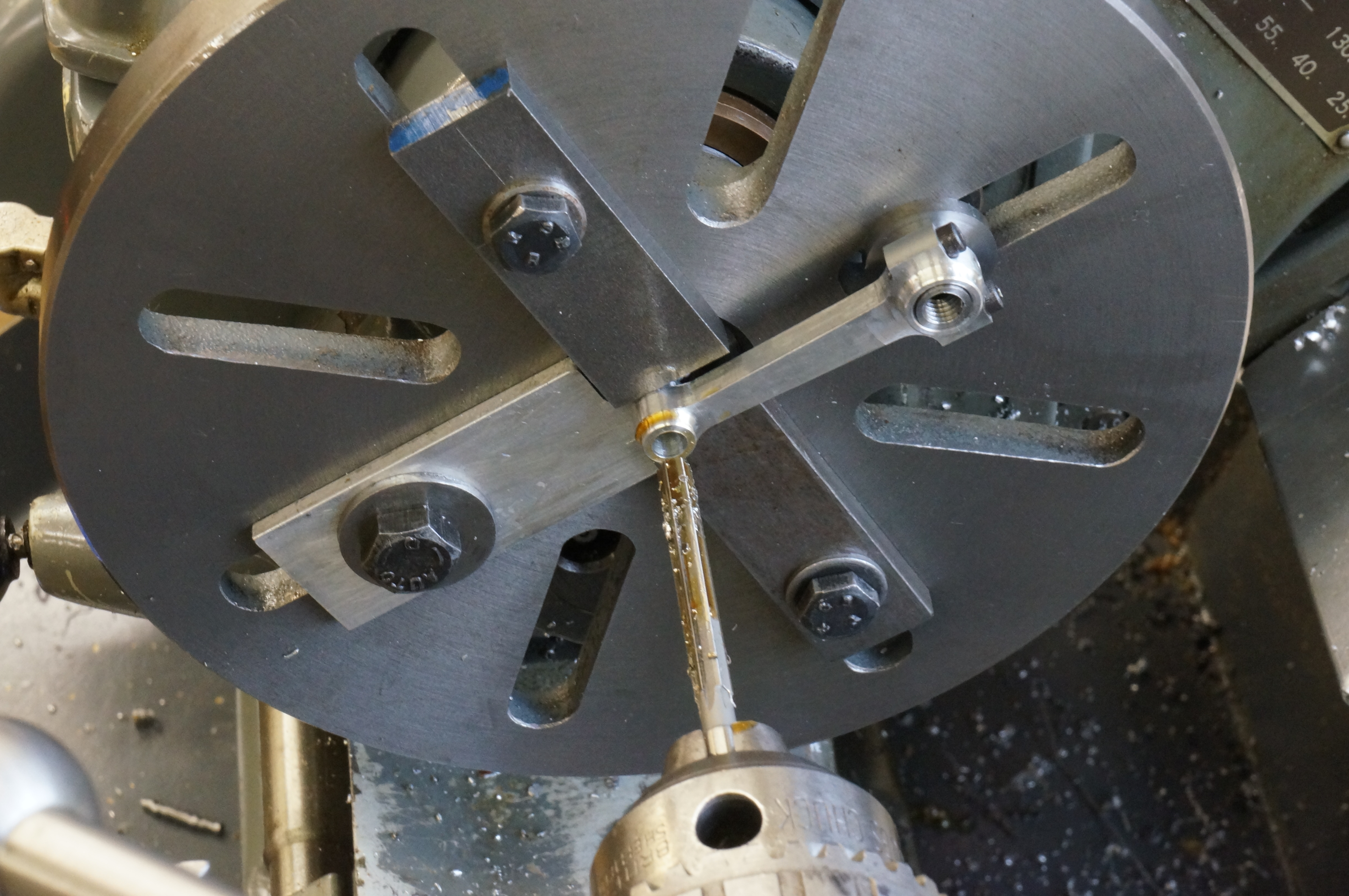
To be sure of getting the holes square to the faces I held the rods in the bottom of the vice jaws with no packing. After lining up carefully, I first restored the hole to round by putting a ¼″ slot drill through, and then used a boring head to take two 0.010″ cuts and one of 0.002′ to leave about 0.006″ for reaming. I thought I had left enough rod sticking out of the side of the vice to be able to get the 9⁄32″ reamer through, but in fact I had to remove one of the vice mounting bolts, and to take the last shave with the reamer by hand after taking the job out of the vice.
I could not drill the little end at the same setting without drilling the vice, so I turned the rod end for end, keeping the same face against the vice. This meant that I had to clock the job up by the big-end bore to get the right centre distance, using the cross-slide dial to measure the distance. The little ends were centred, drilled 3.5 & 3.8 mm at top speed and reamed 5⁄32″ at 700 rpm.
Next, I reconfigured the lathe for turning and made a shouldered sleeve to fit the big-end bore with a 4 mm bolt. I also made a shouldered pin to locate the little end bore centrally on the rotary table for profiling the little ends. A couple of 4 mm washers completed the turned bits needed for milling.
With the 3-jaw chuck replaced with the 4-jaw, each connecting rods was set up true and the outside diameter of the big-end bolting lugs turned to size. This set-up was made easier by not needing softening under the chuck jaws, as all the surfaces will be machined later.
Finally, I hacksawed a piece off an alloy slab to make a fixture for milling the sides of the rods, and while the 4-jaw chuck was still mounted, faced opposite sides of the block. (6 hours)
2012-04-14 - Profile milling
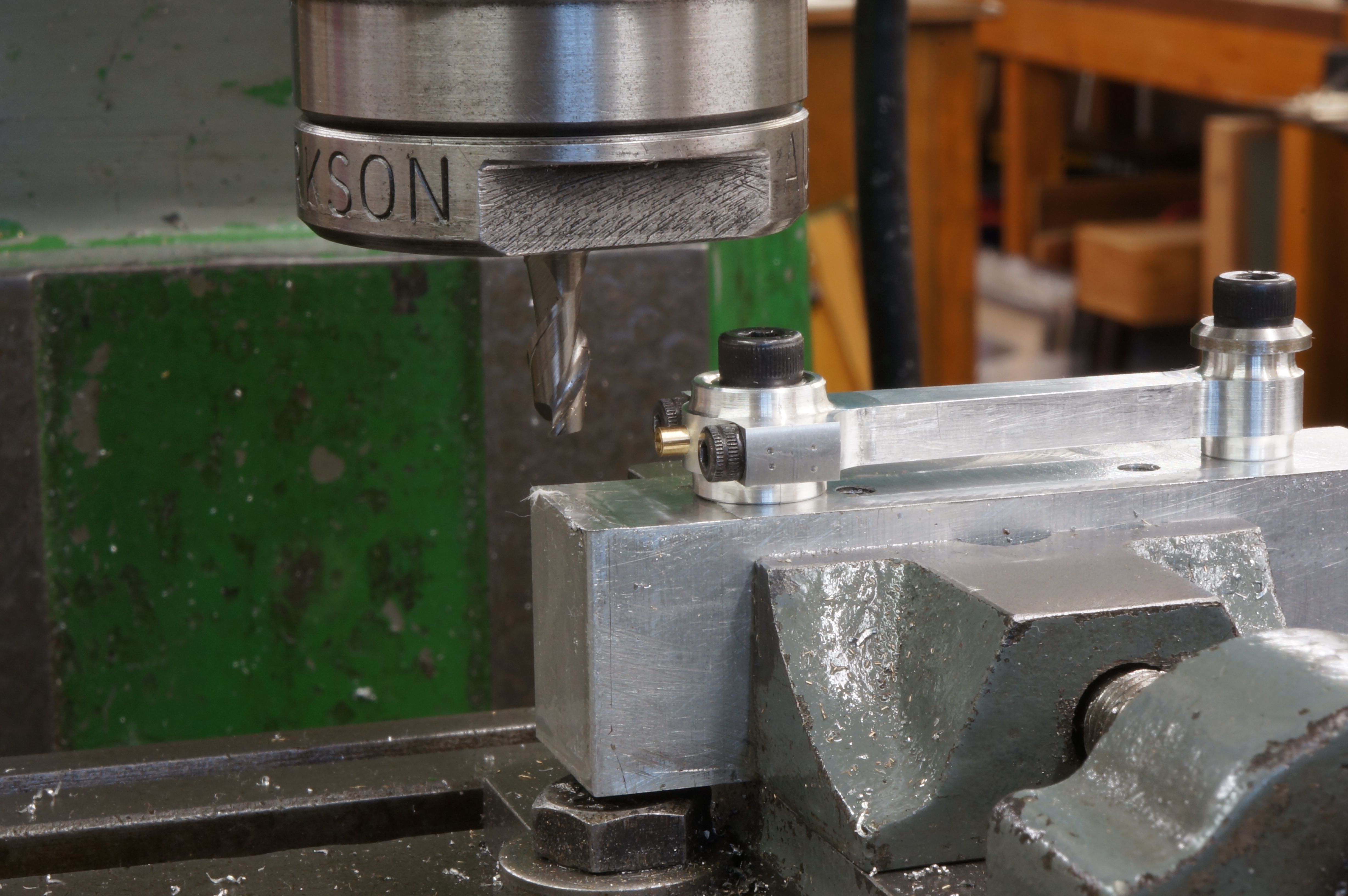
With the alloy block in the milling vice I took a shave off the face to ensure it was true and then drilled and tapped M4 holes 1¾″ apart for mounting the rods.
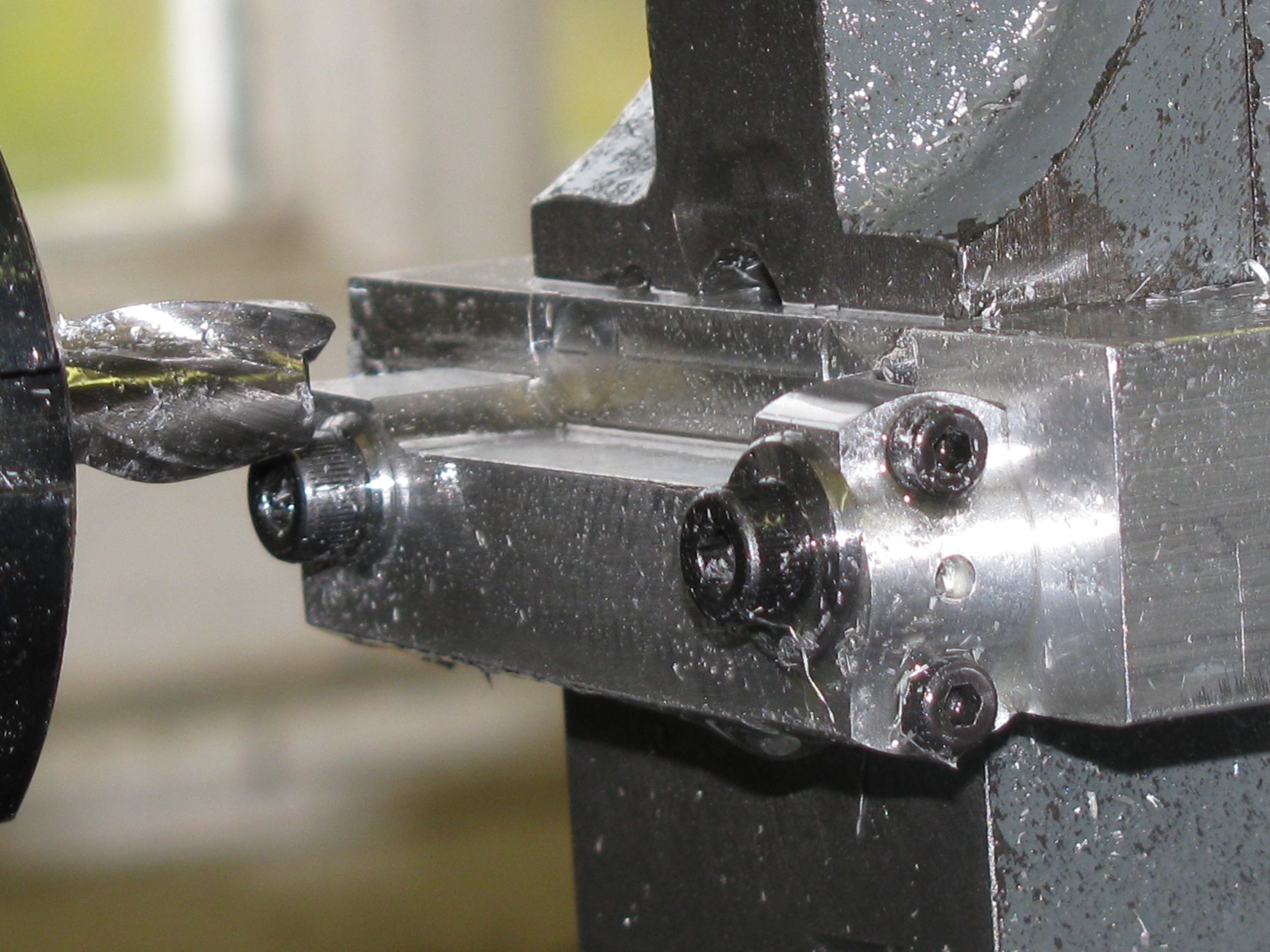
Mounting the first rod, I found there was quite a bit of freedom of position and it was necessary to adjust it to get the top edge level. I milled to a depth of 0.180″ over the whole length, working away from the big end lug and leaving about 1⁄64″. for finishing the lug. Next, I took a further 0.045″ in two cuts of 1.1″ length to start to form the little end. I then worked carefully into the corner with plunge cuts to finish the lug to the correct length and the shaft to the correct width, using a calculated depth reading for the shoulder radius. I left a couple of thou in the bottom to allow for finding the depth of the taper cut by touch, and used this depth setting to make parallel cuts up towards the little end.
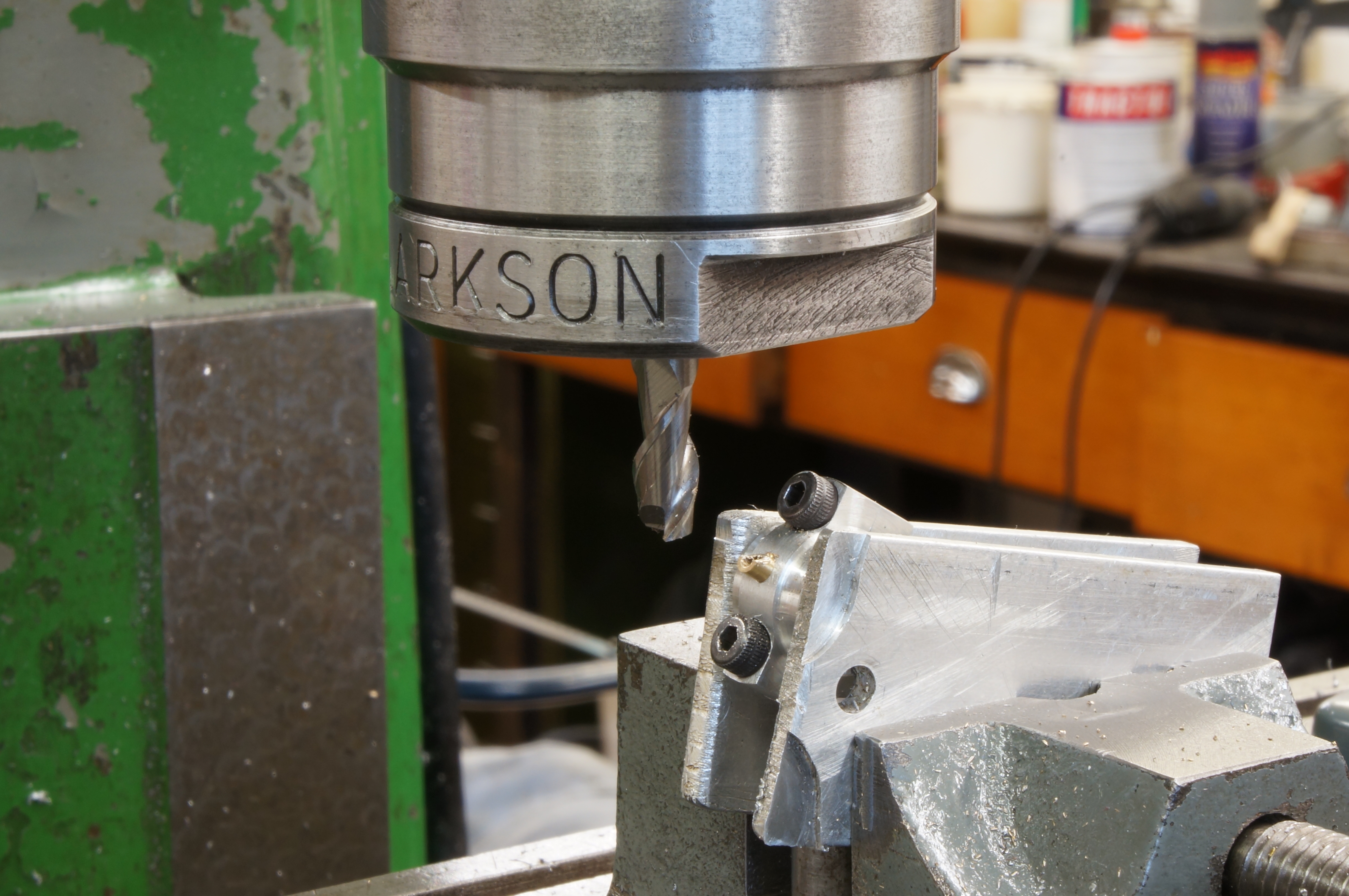
With the sleeve removed from the big-end hole, I re-clamped the rod on the slope, and gingerly cut the flank taper, eventually working the full calculated length to marry up with the circular profile round the little-end.
I started to set the rod up to do the second side, but it seemed to be hard to get it to sit level, so I took it off again while I had a think. (3½ hours)
2012-04-21 - More profile milling
I decided I was right to level the rod for each operation to ensure accuracy. If the range of movement allowed by the bolts makes any difference it will be to the taper cuts, which may result in slight variation of the thickness at the neck, adjacent to the little-end. By pushing down firmly on the rod while tightening the bolts for taper cuts, the slack should be taken up evenly.
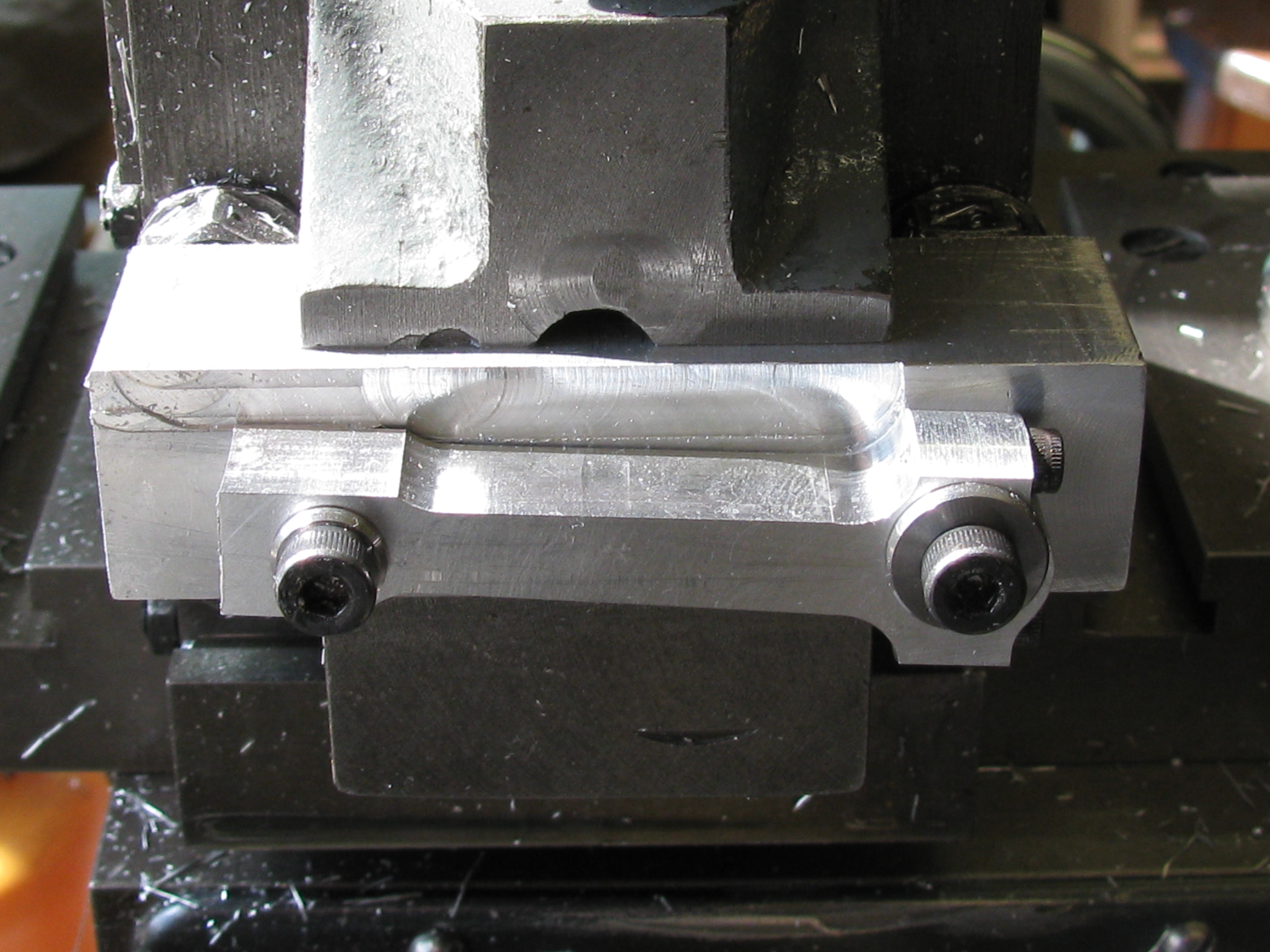
With this in mind, and the rod levelled up for the second side, I again took 6 cuts of 30 thou, leaving 0.018″ over the little-end for finishing the radius. I then took plunge cuts near the big end, leaving about 20 thou to come off the lug and taking cuts of 30 and 15 thou off the flank. A cut feeding upwards finished the lug to length, within a couple of thou of the corner root, and then I took a plunge cut to finish the root, again leaving a shave for finding the root with a kiss of the cutter for the taper cuts. It is safe to find the corner this way if just the edge of the job is used, as a slight overshoot will cut into metal that has to come off to form the bosses anyway.
After repositioning the job and finding the corner datums, taper cuts were taken for 1.169″ length, the value calculated between the end fillet radii. Finally I took vertical cuts over the little-end to trim the rod to 0.005″ thou oversize for finishing. With the rod removed and cleaned up, I measured over the flanks at each end, using 3⁄8″ diameter 'rollers' in the root radii. The thickness was +0.004″ at the little-end and +0.005″ at the big-end, a gratifying result. The second rod was dealt with in exactly the same way, ending up with the little-end neck just 0.002″ under the nominal thickness of 0.205″. (3¼ hours)
.
2012-04-28 - Still profile milling
I took a series of cuts on both sides of each rod to reduce the stem to 3⁄16″ thick. Actually, after checking, the stems were about 0.006″ over thickness, so I decided to take an extra 0.003″ off each side. While by no means necessary, I thought I might just as well take a few more minutes to get it right, and a light finishing cut after taking the bulk off each side is good practice anyway. The milling left tough burrs on the corners, and I spent quite a time removing them without rounding the edges.
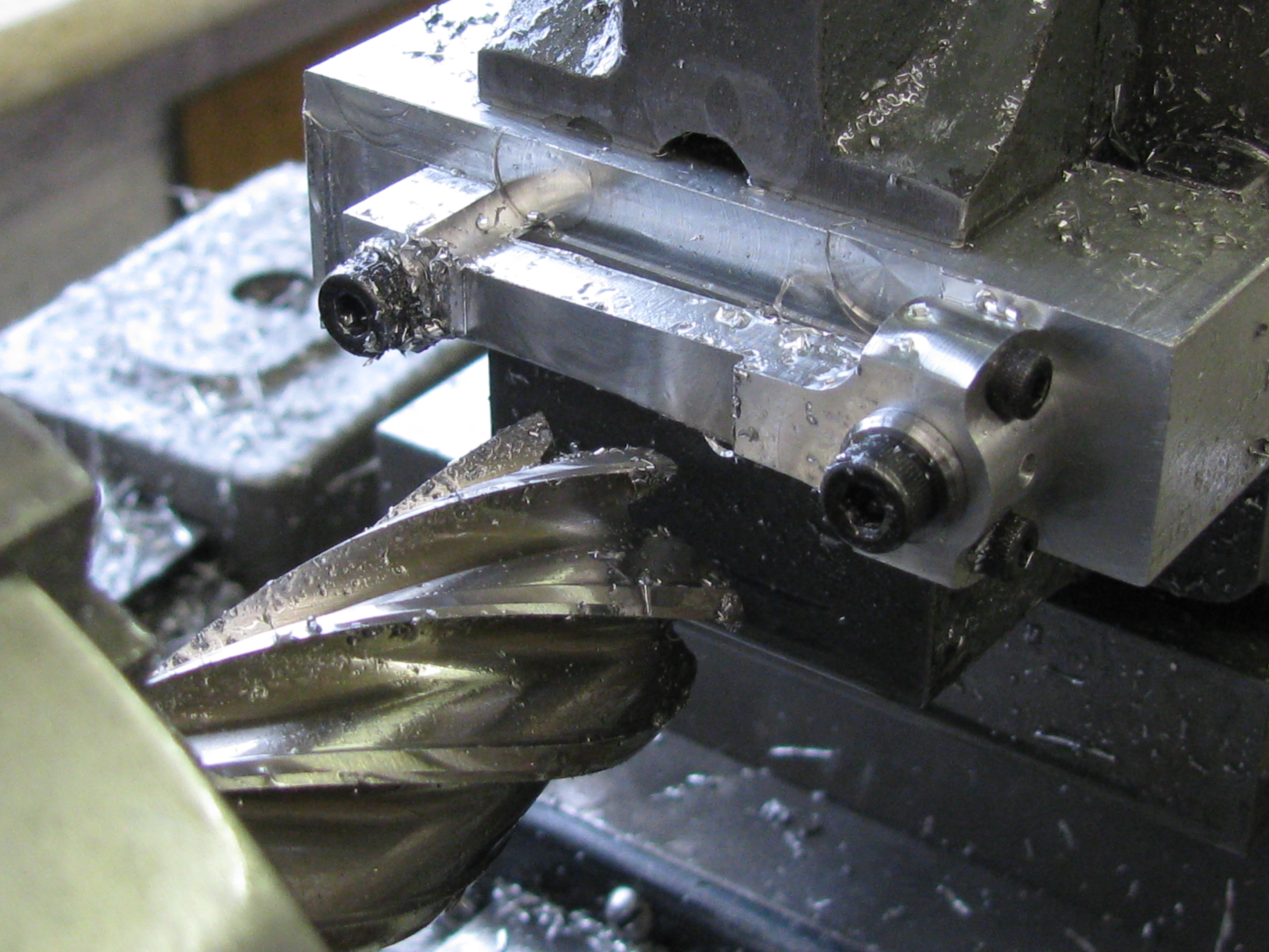
Next I set up the rotary table to mill the profile round the little-end eyes. It is quite fiddly to set the job up, needing a dozen or more small fingers to stop everything falling off before a strategic clamp screw can be nipped up. Let's say it rewards patience. The eye was centred on the table using the previously mentioned pin, and then the hole lined up with the lathe spindle using a clock in the chuck as usual. This means that cuts can be taken along a known axis and the angles of swing of the table can be worked out to get just into the root radii without overdoing it. Setting the stops for 129° swing each side of a zero that is quite arbitrary takes a bit of thinking and double checking when the graduations are four repeats of 0-45-0. I went a tiny bit too deep with the first eye and it ended up 0.003″ under the 3⁄8″ nominal diameter, well within acceptable limits. The second one was within a thou of size.
With the milling done, the lathe was given a good clean down to get rid if the fine sticky slivers of aluminium swarf.
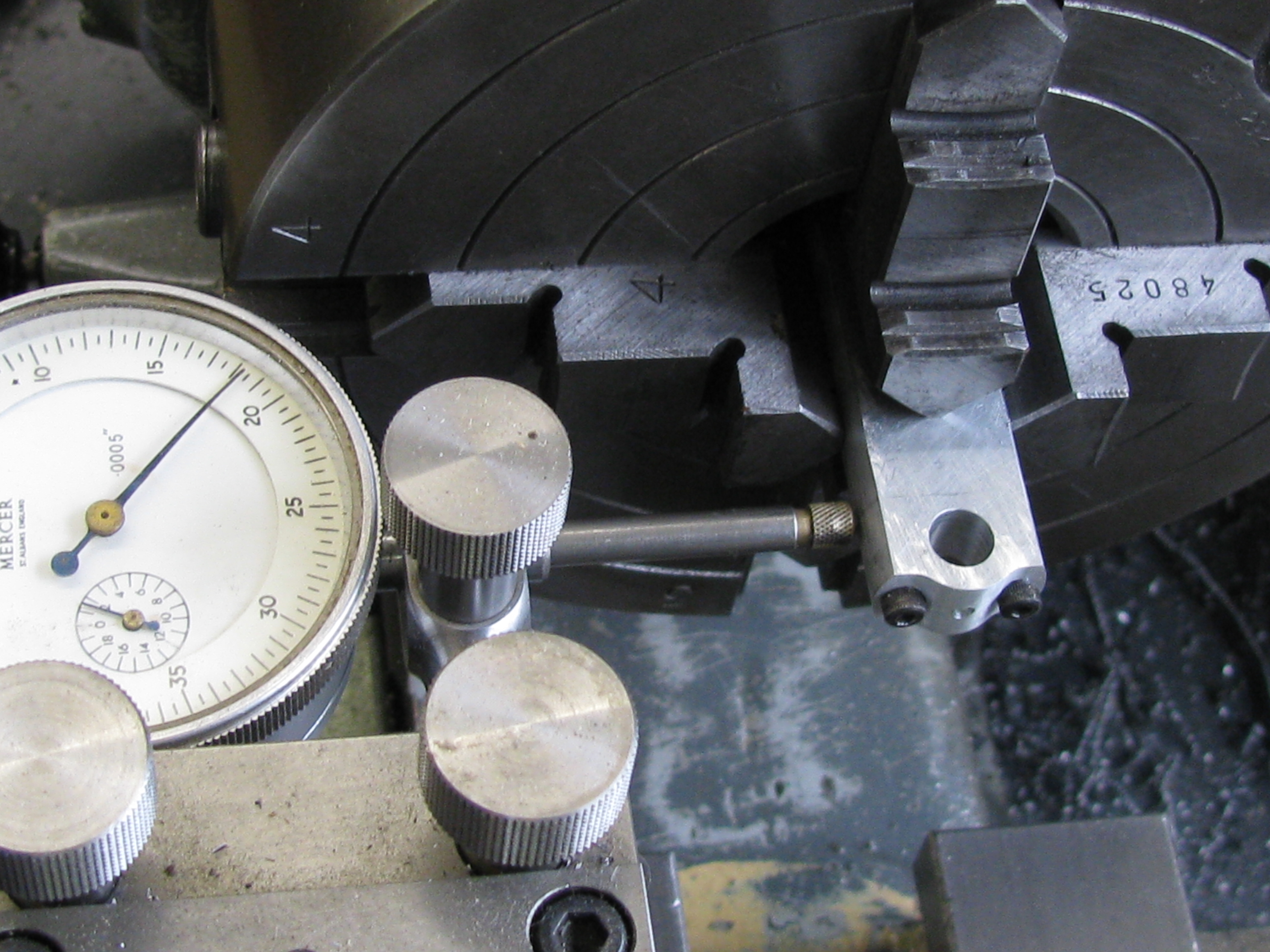
The next job will be boring the big ends, at last. I have been giving some thought as to how to set them up, and decided to try to measure how well centred the existing undersize holes are between the bolting lugs. A quick check with a dial gauge on the surface plate suggests that they are very good, but I need to measure more carefully to make sure. If they are indeed good enough then I can clock from the existing bores, which will make the job relatively simple. (5½ hours)
Considering how to hold the con-rods for boring, I concluded that with a 4-jaw set-up it would be virtually impossible to get the big-and centred and the rod accurately square in two directions. A faceplate set-up seemed more attractive, with the rod fixed to some form of mounting plate, but the size of the central hole in standard faceplate, and the disposition of the slots would make it awkward. I decided there were finally no more excuses for not trying an idea from the long-term back list. I had a spare chuck backplate, and a 4″ disc of steel which has been sitting about waiting for a use some time. (It came from K R Whiston, of "seen my cat?" fame and fond memory to most ancient UK model engineers, so actually it has been sitting about for donkey's years.) These would be used to make a small faceplate, with no central hole and no slots, but instead a matrix of holes tapped M5.
2012-11-25 - Mounting Plate and another sidetrack
So, with the small faceplate duly made (8 hours), and after doing a bit of work on cams earlier today, I started work on a mounting plate for the con-rods. Yet again I found I needed a decent scribing gauge for marking a line parallel to an edge, and yet again I am going to make one this time. Work on the engine is going to have to be put on hold again. This was supposed to be a straightforward, follow the book, project. I should have known. (15 mins)
2012-12-09 - Mounting Plate again
Now, with the scribing gauge completed this afternoon (21 hours), I carried on to finish the mounting plate. Setting up the first con-rod for boring. Late on in the day I find that there is a slight jump from the dial gauge as I rotate the job. The big-end cap has evidently moved. This will need to be investigated. By the time I next get in the workshop I have decided to sort out the timing gear instead.
2013-02-09 - Boring the big ends
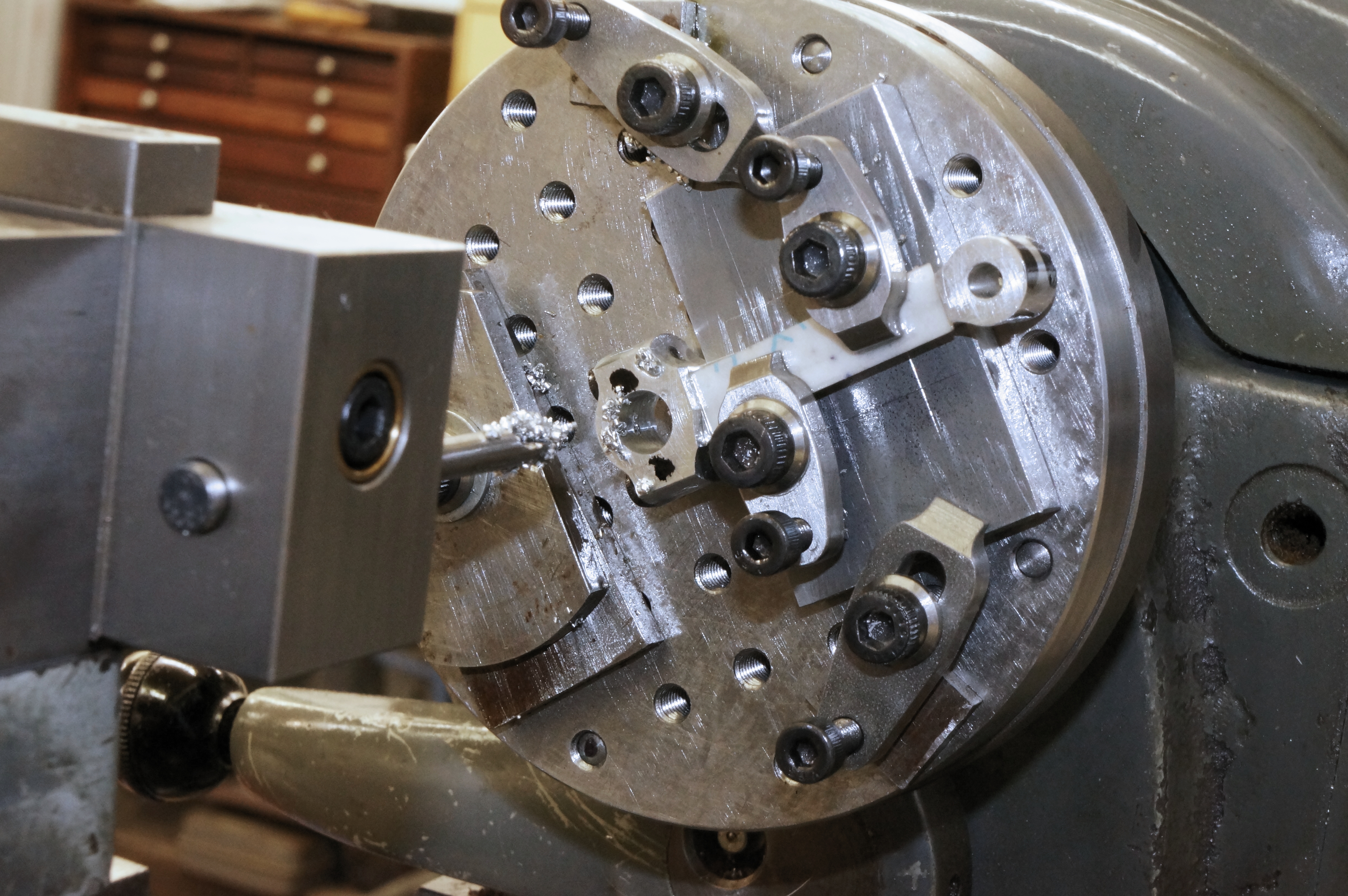
Back with the pilot bores, I checked again their centrality and any misalignment of the caps. One has definitely moved but not enough to worry about. As the external radii of the bolting lugs are the only finished features, I make sure the cap is bolted up with these matching. Both holes are positioned accurately enough to use them as the datum for finish boring.
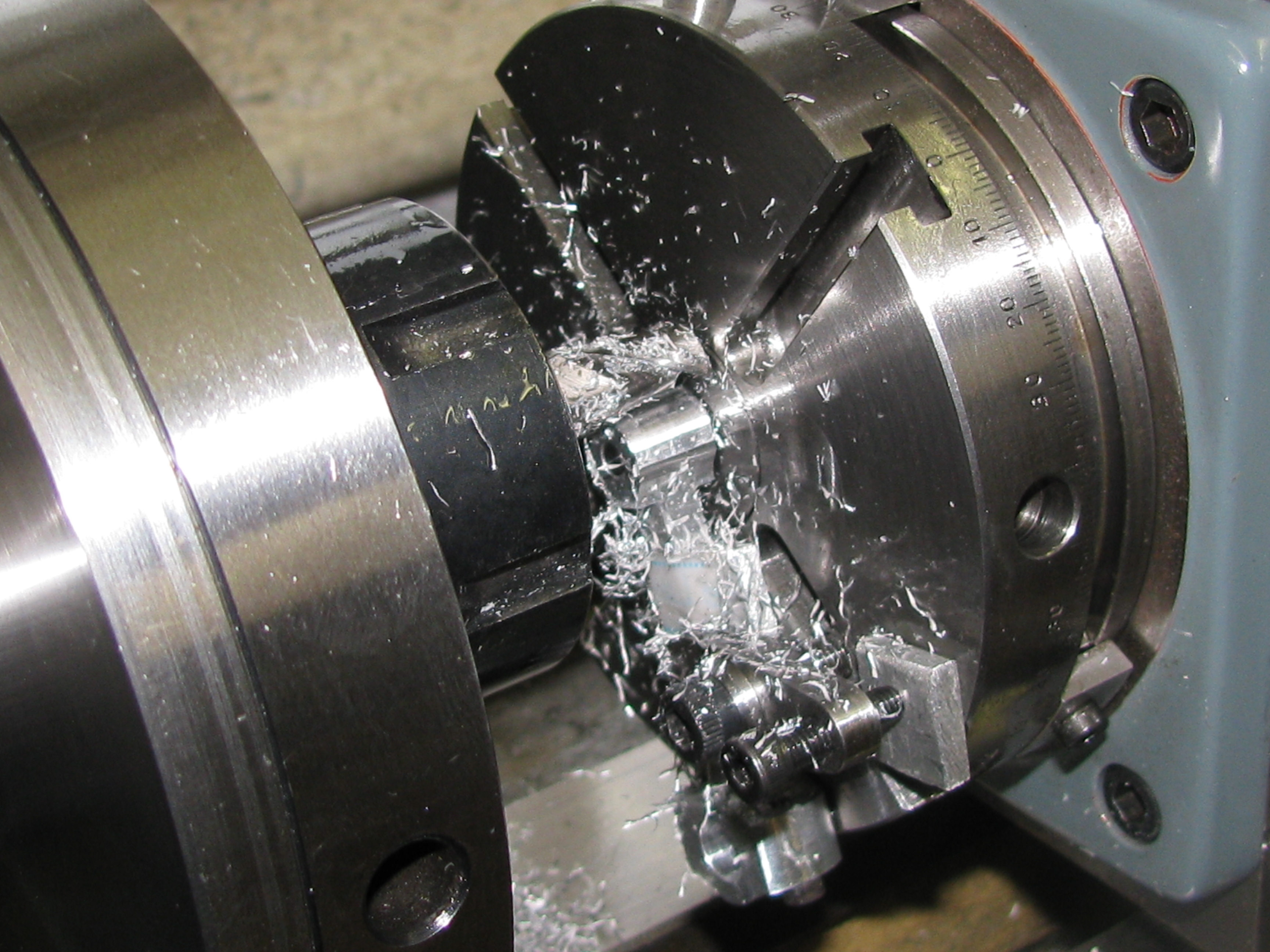
In setting up the better rod, I get the bore running true to 0.000″. Boring at 800 rpm, I take two passes at each setting, taking three successive cuts of 5 thou, one of 1½ and one of ½thou. As the smaller crankpin is at most 0.0003″ down on nominal size, the big-ends can be bored within a whisker below 5⁄16″. This one I measure at -0.0005″ using a Starrett small hole gauge, but using the Moore & Wright gauge with the little balls, it feels closer to nominal. A piece of 5⁄16″ silver steel will not go. That will do. The big end bores need 1⁄32″ radii at the ends to match the crankpins, and as usual I cut a 45° chamfer and then smaller ones at 22½° and 67½° using great care to note exactly when the tool touches the job and then working to dial readings. In this case there was not enough clearance round the projecting clamp screws to swing the toolpost round to do the outer angle. I realised that this would be better done at the next set-up, anyway, as there is still a little metal to be taken off the faces.
With its slight misalignment of rod and cap, the second is a little more difficult to set up, but I still managed to get it running to 0.0008″ TIR. This hole is also bored to rather less than a thou under nominal size. Both big ends can be bolted up onto an accurate piece of 5⁄16″ but are tight. Good. (4½ hours)
2013-02-10 - Big end bosses and radii
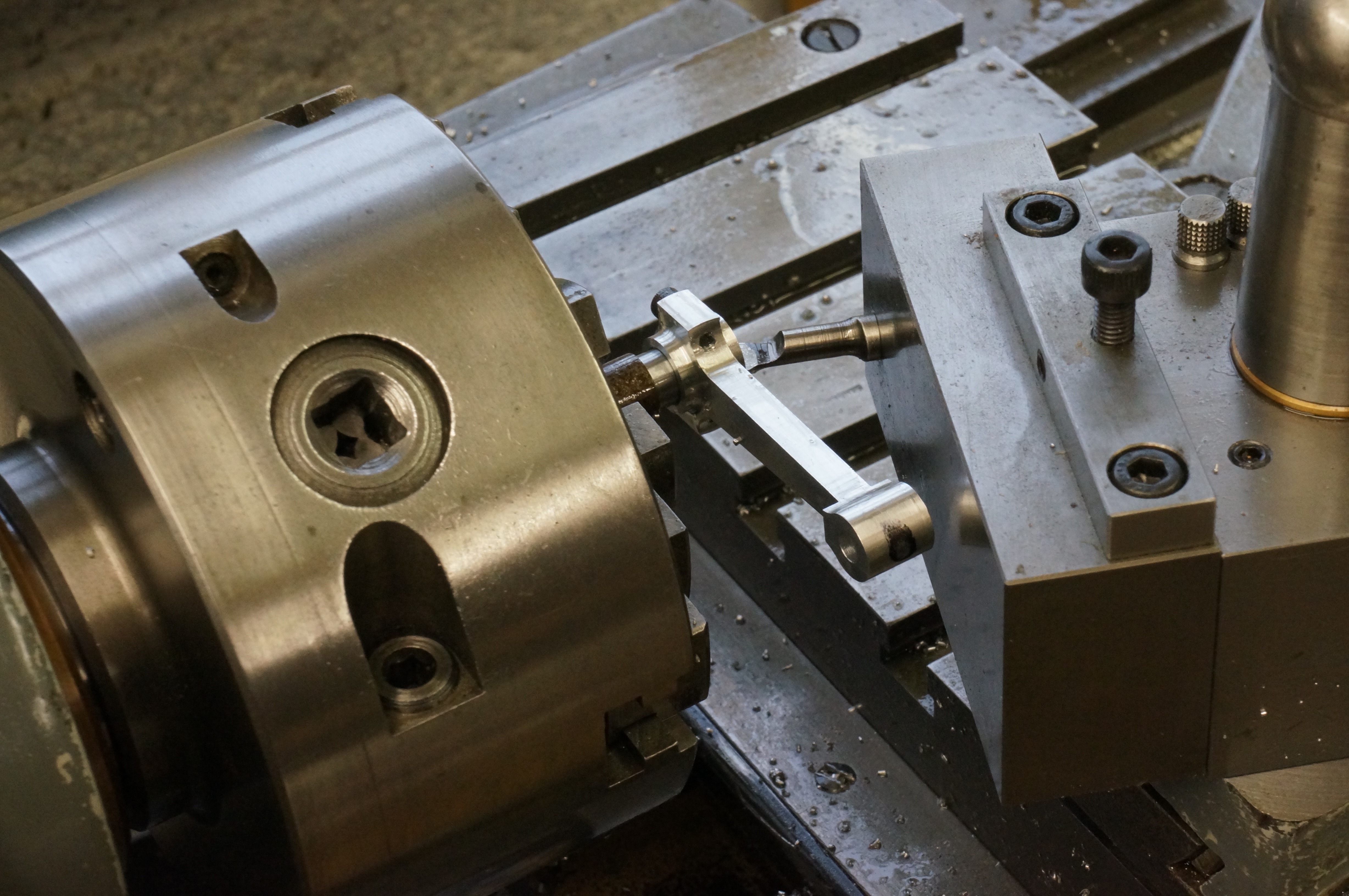
Trying a piece of 5⁄16″ silver steel in the collet chuck I got a run-out of 0.0003″ which would be OK, but I would rather be spot on. Turning a mild-steel stub-mandrel I get a nice finish, dead size. After grinding a tool with a 1⁄32″ radius, I turned the bosses and faced them with just enough clearance between the crank webs, and cut the chamfers 0.008″ on the outside, and internally, feeding 0.018″ at 45° and 0.006″ for the half-angles.
I punched light identification and orientation dots on each rod and cap (marks to go to the camshaft side) and made a start on scraping No 1 rod to the crankshaft. However, really I need to finish the little ends first as I want to use a pin set on the faceplate to ensure the rods are the same length, and I want the big-ends a firm fit on the pin. (4¾ hours)
.
2013-02-16 - Preparing for the little ends
The first job was to make a boring bit to fit in a 5⁄32″ hole. I filed the clearance angles on one of my stock of prepared 3⁄16″ silver steel blanks, then hardened, tempered and honed it.
Next, I wanted to make sure my 3⁄16″ reamer would cut a hole the right size for the silver steel gudgeon pin material supplied in the kit. As supplied this is 0.01878″ in diameter, or 0.0003″ over nominal size. I bored a hole in a little block of aluminium alloy, leaving just 2½ thou for the reamer. This hole was a shade too big, with detectable shake on the silver steel.
I considered making a lap so that I could make the gudgeon pins out of some high-tensile steel, but decided I would first try getting the reamer to cut to size. It was too small to be able to see and feel what I was doing trying to stone the lands, so I tried spinning it with a little garnet paste in one of the test holes it had cut, effectively to blunt the edges a bit. This now cuts (and rubs) a hole that is a push fit on the silver steel as supplied, and a nice running fit on a piece polished to the nominal size.
In making a shouldered pin to mount by the big end, I should have tapped the ¼ BSF hole through it first, as once turned to size it proved difficult to grip tightly enough to resist the torque needed for tapping. Although it slipped a couple of times in the chuck, the diameter fortunately remained on size.
For positioning the pin on the faceplate it would be easiest if I could use one of the con-rods. For this I needed to check the centre distance between the holes. I used the No 2 rod as I had not done any scraping on it so the centre distance would be more accurate. I found an accurately ground 4mm Diameter pin would just fit in the little end, and with a piece of 5⁄16″ silver steel in the big-end bore I could use slip gauges to measure the gap, the correct size would be 1.51525″. Actual measurements were 1.5133″ one side, and 1.5150″ the other, so if I used the latter for setting up, it would be pretty close.
Actually setting up to get the pin in the little end running true proved tricky. Tightening the big end bolts made a measurable difference. I got very close at one point and then upset it again trying to get the last few tenths. Time to stop for the day. (5¾ hours)
2013-02-17 - Little end bores
By sheer fluke I managed to get the 4mm pin in the little end pin running true to within 0.0001". I drilled the hole out to 4.5mm and bored, first pass just touching and then a cut of 2 thou taking the hole to 0.1835″, then reamed with the doctored reamer. The hole was tight. The oversize silver steel would not go in. After two more passes with the reamer it tried the sized silver steel test piece which was a nice fit.
Turning the boss diameter sounded wrong with the job seeming to be rattling round a bit, so I stopped leaving a few thou. Most of the area of the bore is good, but there is also quite a bit scoring. The bosses do seem to move about a little while turning, but, in so far as I can make out from my notes writing this 18 months later, I seem to have decided they were OK, reversed the rod and turned the other side, and and carried on to do the same jobs on No 1 con-rod. I don't think I faced the bosses to final size at this stage.
On checking the resulting holes I found that while they were accurately co-planar, they were out of parallel to a disappointing degree, probably worse than a thou per inch. This needed thinking about. (2½ hours)
2013-02-23 - Little end bores again
I have bought new 3⁄16″ and 13⁄64″ reamers, and have tried a couple of the larger holes in a light alloy block. Although sold as hand reamers they have straight flutes and cut mostly at the tip even when presented with a hole just 1½ thou below nominal size, which seems more like a machine reamer to me. It also seems to cut well over size, and slightly tapered. I found the holes tighten on a piece of mild steel polished to 0.2039″ but are a running fit on 0.2037″.
Looking for a way to support the little end for re-boring, I decided I could use a plate with a finger to fit between the lateral locating pieces and behind the little end. (2¼ hours)
2013-02-24 - Little end bores again
Having made a suitable support tab, and trimmed the lateral supports to suit, I set up a rod to have another go at the little-end bores. I bored the first one to a shade under 0.200″ and reamed it in short pecks, using Rocol RTD paste and running at 200 rpm. With the second rod, the existing hole was some way out of true but came good after a couple of cuts with a boring tool, and reamed OK. I then finished the remaining turning and facing of the bosses on each side, having to re-mount one because I had forgotten the chamfer.
With a turned rod in the little end and 5⁄16″ silver steel in the big end I tried measuring the gap both sides with slip gauges. This is not easy, and I am not sure how reliable the measurements were, so I am not going to reproduce them here. Suffice it to say the holes still seemed to be miles out of parallel and I was puzzled and disconcerted. (4¾ hours)
2013-02-25 - Bronze bushes
I have decided that a different and more rigid set-up will be needed to get these bores right. I do not want to bore them out even larger, so bushing them and boring the bushes to the original size seems the answer. This will result in a bush with a wall thickness of only 0.008″, but it will be supported by being firmly Loctited in place, so I think it will be OK. First I turned some hard phosphor bronze for these bushes, but I took a bit too much off in the final cut, which was as well because I decided I did not like the materials machining properties anyway, so I tried again with a bit of bearing bronze and turned it to 0.2038″ diameter. I parted a couple of pins off, 1⁄64″ over length. These and the bores were carefully cleaned with Loctite cleaner and the bushes fitted with Loctite 641, which cured almost instantly. Finally I faced the bronze back flush. (1½ hours)
2014-05-28 - Setting up
For another go at boring the little ends I decided to use the same mounting plate as I used for the big ends. The big end locating pin has remained undisturbed in the standard faceplate, and the first job was to mill a cut-away in the mounting plate to clear the flange of the pin.
To ensure I could make a good job of boring the bushes, I made an experimental one. One the little boring bit was reground to remove a chipped edge it cut nicely. (1¾hours)
2014-05-30 - Boring again
With a little oil, the reamed hole in the trial bush soon adapted to a piece of polished silver steel measuring 0.1880″ diameter, although neither is perfectly round. I am satisfied that this hole is good enough to carry on with the little ends. they will probably need a little polishing to make a good running surface, but that should be enough to allow the gudgeon pins to be a slightly tighter fit in the pistons.
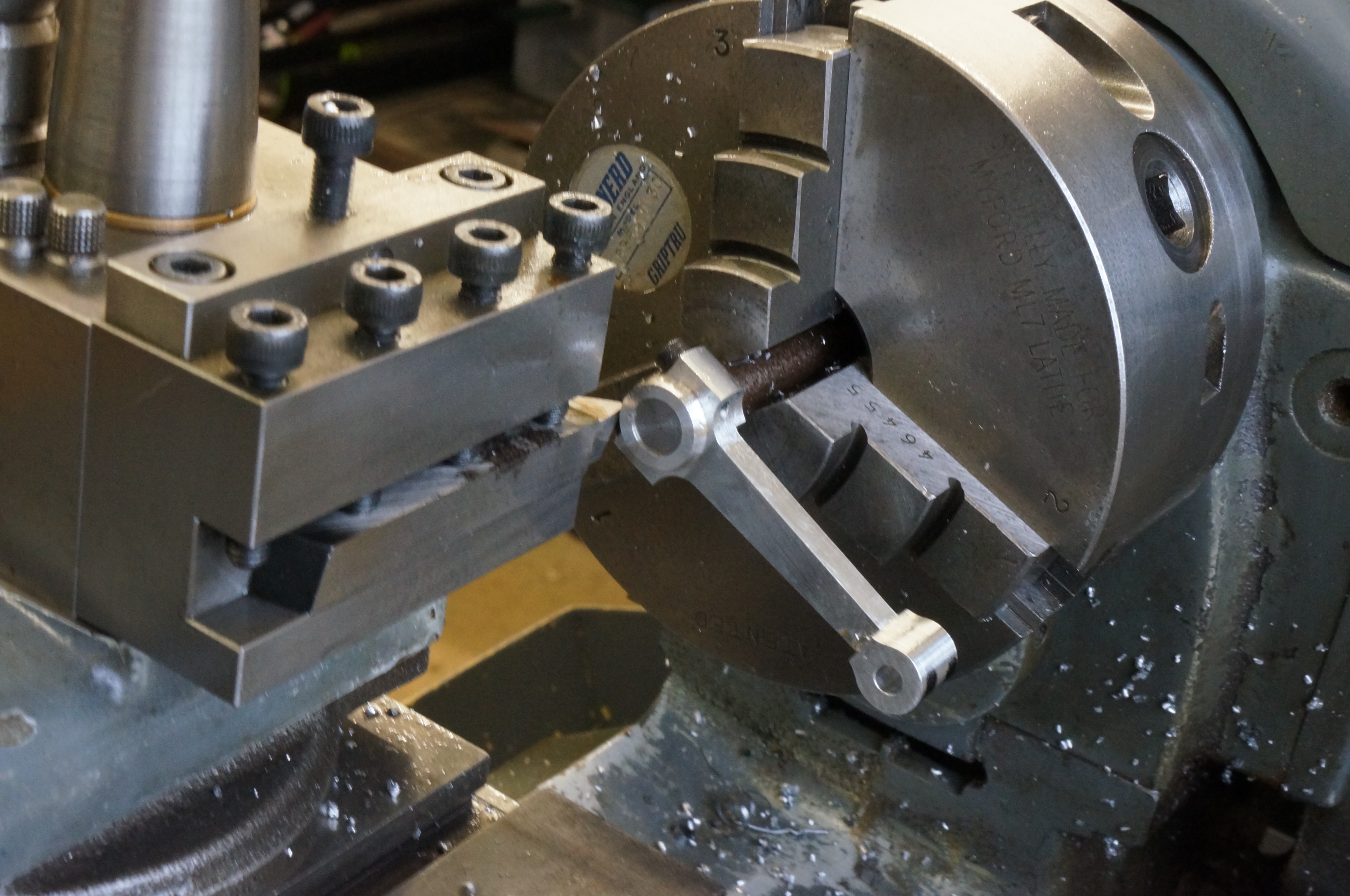
I set up No 2 rod for another attempt. I got the previously machined external shoulder pretty true from side to side, and it was about 1½ thou TIR out radially (along the length of the rod) which seemed pretty good. With balance weights added to the faceplate it was smooth enough at 1000 rpm. I drilled 4.0 & 4.4 mm, to a measured 0.1765″ and took a 5 thou cut to 0.1775″, just over one thou to 0.1783&Prime, 1½ thou for 0.1847″ At this point I put my old 3⁄16″ reamer through and measured 0.1878″. Using a Starrett gauge (the expanding half-ball type) the bore felt smoooth and parallel. That will do. A check on the geometrical accuracy showed the big and little end in plane to about 2 thou per inch, and parallel to about 1 thou per inch. I would have liked better, but that will have to do.
I could not get No 1 rod quite so accurately set up, but the boss was within 0.003″ TIR. I took five successively smaller boring cuts before reaming. The resulting hole was 0.188″ at the mouth, tightening a little towards the back. This one was more accurately coplanar, to within 1 thou in 3 inches, while the parallelism was again about 1 thou per inch.
Tidy up. (5¾ hours)
2014-06-03 - Tweaking
Reviewing the little end holes, No 1 is slightly tighter than No 2, and I want the little ends a less tight fit than the pistons. The new 3⁄16″ reamer would nearly go through, so with plenty of RTD compound, and twisting the reamer gently in my fingers, I took a final tiny shave off both bores. They are now both a close running fit on a 0.1878″ diameter piece of polished silver steel.
Finally I think the little ends are OK. The geometrical accuracy is still less than brilliant, and I am still not sure why. We will have to see how it goes on assembly. The rods still need big-end oil scoops and little-end oil holes, as well as scraping the big ends to the crankshaft. (¼ hour)
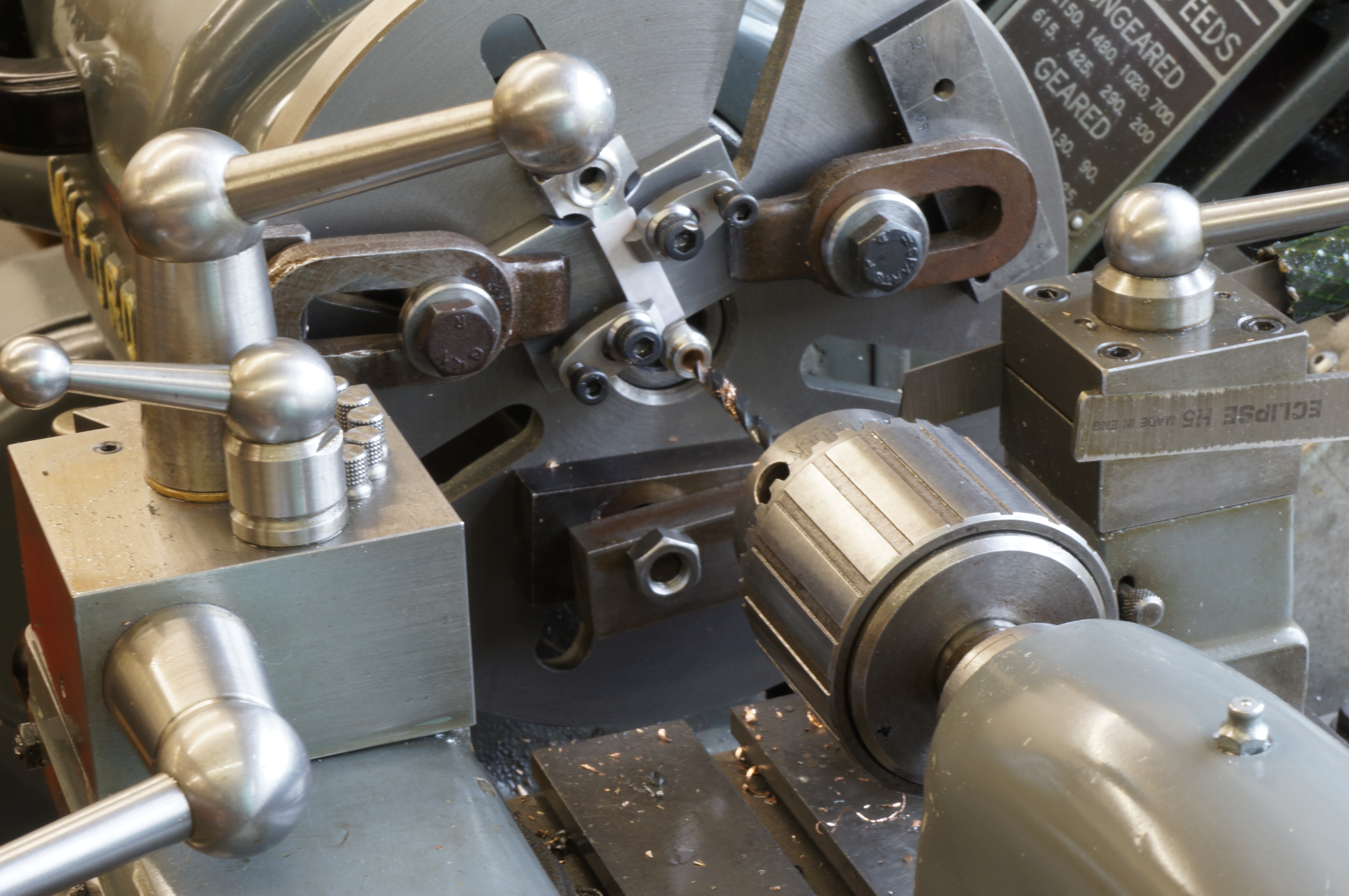
2014-08-22 - Oil Holes
I sharpened a 1.6 mm drill and put the oil holes in the little ends. Checking on the holes for the oil scoops, the holes are a little over size and the scoops would fit better a 0.095″ diameter. I turned them up in brass and Loctited them in place (No 603), leaving them 1⁄64″ over length. Before cutting them down I thought to check the actual clearance over the sump trough. This turned out to be about 0.005″ over design, so nominal will be good. I faced a piece of 3/8 bar to length to make a prop for setting the rods at an angle for milling the leading side cut-away in the scoops. (3½ hours)
2014-08-25 - Oil Scoops
I used a pair of completely over the top set-ups for finishing the scoops; filing would have been quicker and almost as good. First I mounted the rods on a a milling block to trim the scoops to length, and then used the angle setting prop for milling the side cut-away. I adjusted the cut by eye (with headband magnifier) to get the right depth of cut and ensure the whole face was cut, but without cutting into the alloy cap. Getting them right involved sitting on a stool in front of the milling machine with my nose almost on the work. (1¾ hours)
.
2014-12-31 - Fitting No 1 big end
The workshop was too cold this morning, so I decided on a job I could do on the kitchen table. I scraped in No 1 big end bearing to the crankshaft. I got it to a nice running fit with no tight spots, and no play when oiled. Dry, there was the slightest play detectable at the little end. (2¾ hours)
2015-01-08 - and No 2
Again in the kitchen for comfort, I scraped in No 2 today. I left it with a slight tight spot when cold. The rod does not quite drop under its own weight in one position. When the parts are warmed a little on a radiator it is smooth. The rods now just need polishing and they are done. (3¼ hours)
.