
Starter
Having seen this video of a Seal and its starter I then added it to this discussion at HMEM. Surprised and intrigued, I decided to investigate.
The motor in the clip turns out to be a Graupner Speed 400. I looked around and bought, very cheaply it seemed to me, a Speed 320 motor from Howes Models. There seems to be very little information available about it, other than its rated voltage is 7.2 and it draws a current of 0.3A at a no-load speed of 21,000rpm.
Upon further investigation, it appears that this is an (obsolete?) brushed, permanent-magnet motor. Apparently these motors correspond quite closely to a linear torque curve from a maximum when stalled, to zero at max speed. This gives rise to a parabolic power curve with max power at half the no-load speed. So in this case that is close to 10,000 rpm.
The forum discussion suggests an engine cranking speed of 300/400 rpm. Taking the higher figure, that would suggest a reduction ratio of 25:1. Used for short bursts the motors will take a considerable over-voltage. On the other hand, they are most efficient at high speed and low torque, and run hotter at lower speeds. This should not be a problem, once I have an engine that starts easily. Hmm.
A 7.2V drill battery showed 6.5V when it had not been charged for more than a month and 8.4V immediately after charging. I made a balanced torque arm to find the motor stall torque. The piece of 1/4 x 1/8 steel I had in stock was enough to make a bar 160mm long over all. A test with the electronic kitchen scales gave a force of 20g at the first reading then dropping to 14g for another two or three readings, by which time the motor was quite warm.
So, the stall torque is 0.014 x 9.81 x 0.08 = 0.011Nm, and the maximum power (torque x speed) will be about .011 / 2 x 10,000 x 2 x π / 60 = 5.75 watts. Allowing for about 97% efficiency in the gears, that gives an initial torque at the crankshaft of 0.25Nm and 0.12Nm at cranking speed.
Having got this far, and unsure if the motor would be up to the job, it occurred to me that I have a collection of spur gears of about the right size in the old Meccano box. These gears are 37.5/38 DP. A 4:1 x 3:1 x 2:1 train was soon built. I started collecting bits and pieces. M2 and M1.6 cap heads and taps were enough for a first stab. A couple of extra holes in one of the 11 x 5 hole flanged plates to mount the motor, and a 2mm to 5⁄32″ rigid coupling were all that was needed to try it. This was a bit rough and ready but showed some promise. The main problem was poor alignment of the motor shaft extension with its outboard bearing in an ancient Meccano plate, not brilliant at 20k rpm. It was again good enough to go further. I learned a little about radio control car hardware and bought a 7.2V, 3.3Ah NiMh battery pack and charger, thick wires with Tamiya connectors, and a 5A ammeter.
2020-02-08 Improving the drive train
In trying all this it was clear the motor shaft arrangement would not do. I decided to sacrifice the 15T Meccano gear. I turned a shoulder on a piece of ¼ brass bar to fit the bore of the gear (well over the nominal 5⁄32″ diameter) for 1⁄8″ length and Loctited the gear in place, in situ in the lathe, with a centre in the tailstock for alignment. I parted off most of the gear, including its hub, as still usable, while leaving a 3⁄32″ wide slice attached to the bar. I faced off, centred and drilled the end, 2mm diameter to fit the motor and cross drilled and tapped 1.6mm for a fixing screw.
With the new gear simply mounted on the motor shaft and the gear train tidied up, replacing a particularly eccentric 57T wheel on the second shaft, it all ran much more sweetly. I measured the output shaft at 995 rpm, indicating a free running motor speed of 24,000 rpm. The current was 0.5A, much the same as the free running motor, so the unloaded train was putting insignificant load on the motor. Gripping a wheel on the output shaft with a rag, I could load the motor up to 4A or more without anything appearing to be unduly perturbed.
To try this rig out, the next thing I needed was a load. At this stage the engine had not run, and still had very little compression. A realistic starter test could not be carried out until it had some, so seating the valves was the next job.
2020-03-22 Trying different ratios
With decent compression established, I could try things out. First I tried the 24:1 ratio already set up. The motor would not crank the engine at all. By adding another 3:1 pair to the gear train I tried it at 72:1. This produced a free speed measured at 336 rpm, indicating free running, and a loaded cranking speed of 275 rpm, drawing about 2 amps. This indicates a motor speed of 19800 rpm. Next, I swapped the final drive to 2:1, for a 48:1 overall ratio. this gave a cranking speed of 355 rpm, at a current of 3 amps and a motor speed of 17040 rpm. Finally, I took out the last set and changed to a 4:1 x 3:1 x 3:1 set for an overall 36:1. With this set the motor drew over 5 amps and it all sounded thoroughly unhappy, so I did not make it wait while I measured the cranking speed. It was too slow to be useful anyway. (2¼ hours)
So far, then, the best choice is 48:1, and I have exhausted the range of ratios I have the parts to make up. In the evening I had a search around the wonderland that is Meccano Spares and ordered a 95 tooth gear so that I could try a 5:1 pair in the reduction train.
2020-03-28 Trying more ratios
With the new gear I set up a 40:1 train of 4:1 x 5:1 x 2:1 while the 7.2V battery was charging. This gave a cranking speed of 320 rpm, at a motor speed of 12,800, theoretically close to the maximum power point, and a current off the scale of my 5A meter. Again swapping the final pair to 3:1, for a ratio of 60:1, I got the same 320 rpm cranking speed at about 2.8A and a motor speed of 19,200 rpm, not much less than with the 72:1 ratio.
Clearly, the best cranking performance is to be had somewhere fairly close to the 48:1 ratio, as shown in the video clip. The characteristics of this motor do not seem to correspond very well with the little theory I know. At 3A, it is using well over 20W, but seems quite happy at that. I don't have any measure of the output power though. I think this is promising enough to justify some design work to try to produce a compact reduction box using commercial gears and ball bearings.
I have also bought a sprag clutch. It is 22mm OD, and that is likely to be a determining factor in the gearbox design.
If I find I am a bit short of power I can always increase the voltage.
| Starter motor reduction ratio | |||
|---|---|---|---|
| ratio | cranking speed | motor speed | current |
| 72:1 | 275 | 19,800 | 2.0 |
| 60:1 | 320 | 19,200 | 2.8 |
| 48:1 | 355 | 17,400 | 3.0 |
| 40:1 | 320 | 12,800 | > 5.0 |
.
2020-11-03 Trying nylon for a coupling
As a part of setting up to run the engine, using the lathe as starter motor, I need a coupling to the timing end of the engine. The starter unit will also drive the timing end of the crankshaft, so I decided to investigate making a suitable coupling. I am thinking in terms of a dog (aka jaw) and spider coupling. and the first consideration is what to make the spider out of. I have a small piece of 10mm thick white nylon plate in the material oddments box, and that seemed a possibility. I cut a piece out and milled it to a rectangle. This produced a lot of burring which is difficult to remove cleanly. (1 hour)
2020-11-05 Milling the spiders
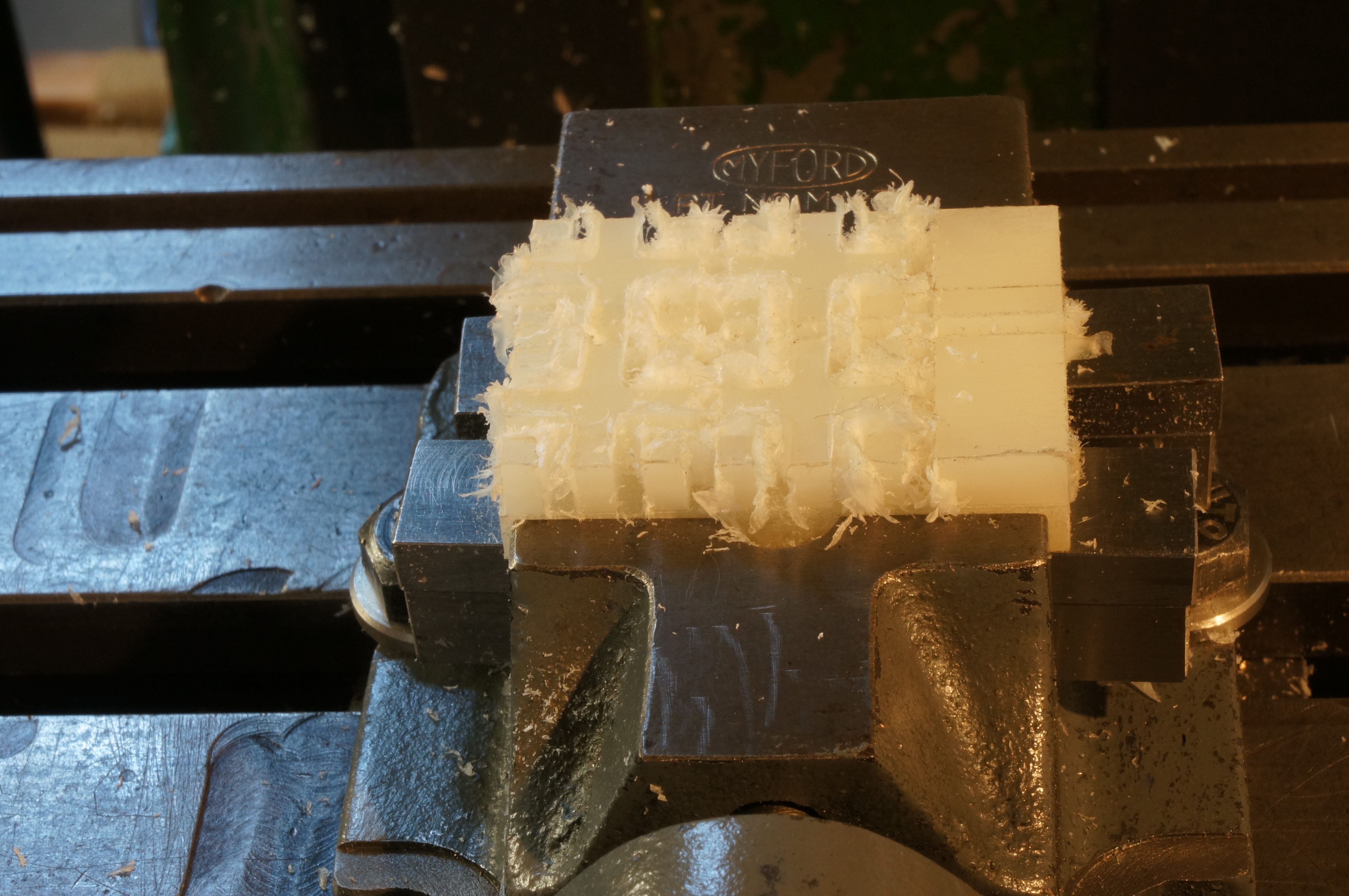
Firstly I milled grooves to form four squares of white chocolate, and then milled out the corners. I used a 3⁄32″ slot drill running at 2200rpm. Again, this produced a lot of burring. A lapse of concentration means two of the spiders will have a thin leg. I decided deburring would be easier with the pieces separated, so I sawed the block to individual pieces and started cutting the waste out of the corners. (3¾ hours)
2020-11-14 Trimming the spiders
I continued hand trimming the nylon spiders. Differences in surface finish taught me that I should not climb-mill nylon. I milled one spider to final thickness and tidied it up. The result is not bad. (time not recorded)
2020-11-15 Making a drive dog
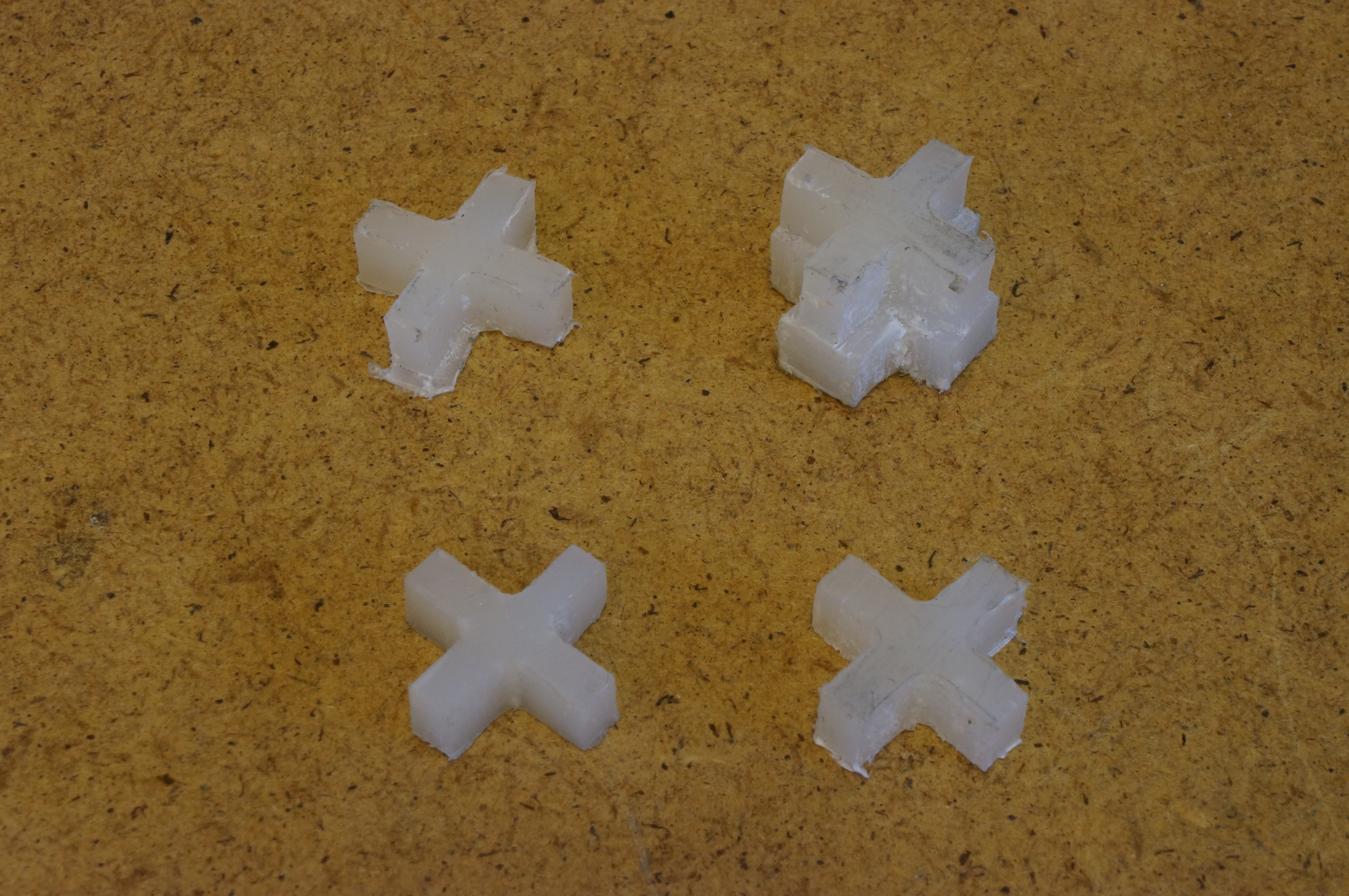
Today I started by turning a trial crankshaft drive dog, then I continued finishing the spiders, milling the backing material off three more. The photo shows them in various states of completion. Finally I milled the dog teeth on the coupling. When nearly finished I turned a handle the wrong way and one dog has a bit missing, but it will be good enough for evaluating the design. A spider is a tight fit but looks good, and the dog can be used as a chuck for finishing the spiders to thickness. (4¼ hours)
I am happy with the general idea of this coupling for the starter, but decide to use another arrangement for getting the engine running. There will be some delay before work resumes on the final design of the starter.
2021-07-24 Starting the Starter
With some other jobs out of the way and most of the materials to hand, I made a proper start on the gearbox today.
After checking the gears, I made the primary and secondary layshafts and Loctited the two gears on each shaft. The second shaft has a slightly reduced portion to allow enough clearance for the input gear on the first. After fitting the gears, I found I needed to increase the length of the reduced part, which was a bit tricky with the gears in place. The four bearings all fitted OK, one barely tight enough, the other three being a tight push to light press fit. Assemblies oiled and bagged. (5½ hours)
2021-07-31 Staring the output shaft
I started work on turning the output shaft, parting off, facing to length and centre drilling, drilling and tapping both ends. Tapping the M2 holes was a pain. I may have used a slightly undersize tapping drill to be sure of getting a good thread. I dismandled the torque limiter that was used in getting the engine started to extract the sprag clutch, which is now needed for the starter. (1¾ hours)
2021-08-01
Working with the output shaft between centres, I turned the 5mm seating for the drive flange and the one for the sprag clutch to 7.99mm. I had to debur the edges of the keyway in the sprag clutch to get it to fit, and after doing that it was a slip fit - a little bit easier than perfect. I turned the bearing seat to 0.2365″ leaving a bit for polishing, to fit the bearing and for the oil seal to run on. (2¼ hours)