
Flywheel
2010-10-23 - Parting Off
I think the piece of 2½″ mild steel bar supplied for this may have been an end or offcut as there were some marks of previous work on it, including a partial saw-cut, and it was well over length. Firstly I faced up both sawn ends. Not wanting to have to machine away or waste the nearly ½″ excess bar, I decided to part it off. Using the narrow parting tool I got to a depth of 5⁄8″ (half way) before it jammed, and thereafter it jammed too regularly to allow me to make decent headway, so I gave up and hacksawed it the rest of the way. Finally I faced both the cut surfaces. I now have a flywheel blank and a useful steel disc.
2011-03-18 - Preparation
Today I resumed work on the engine after a break of almost exactly four months, during which time, among other things, I completed a George Thomas design Small Bending Rolls, also a Hemingway kit.
I made a between-centres mandrel for the flywheel, and a taper reamer for the bore. The taper-turning attachment has not been moved since the crankshaft was machined, so the tapers on these jobs should be just right. For cutting tools made of silver steel I like to normalize the material first by heating to bright red, and burying in vermiculite until it is cool. I this case I roughed cut the taper beforehand. As the surface of the finish-turned taper was still rather rough, I polished it a little, even though there is a risk of upsetting the accuracy of the taper. After milling to a D section, hardening and tempering, and honing the flat face, I found it would not cut.
I tried boring a taper in a test piece, using the top-slide just set to 5° on the scale. It machined very nicely but it was a bit tricky to measure the size. I decided to try using a 5⁄16″ steel ball. A bit of trigonometry allows the diameter to be calculated from the depth the ball goes into the taper. I decide to forget about the reamer, and bore the taper in the flywheel. (5 hrs)
2011-03-19 - Grooving tool
Today I ground up a narrow tapered tool with a 1⁄32″ nose radius for machining the pulley groove. I found it hard to get an even radius all round. Next job - Quorn grinder.
Making a start on the flywheel, I roughed out the shoulder at the front. The piece of bar was nominal size as supplied, so I wanted to get it running as true as possible, which was not made easy by it being irregularly out of round by up to 15 thou. (2 hrs)
2011-03-20 - First and second operations
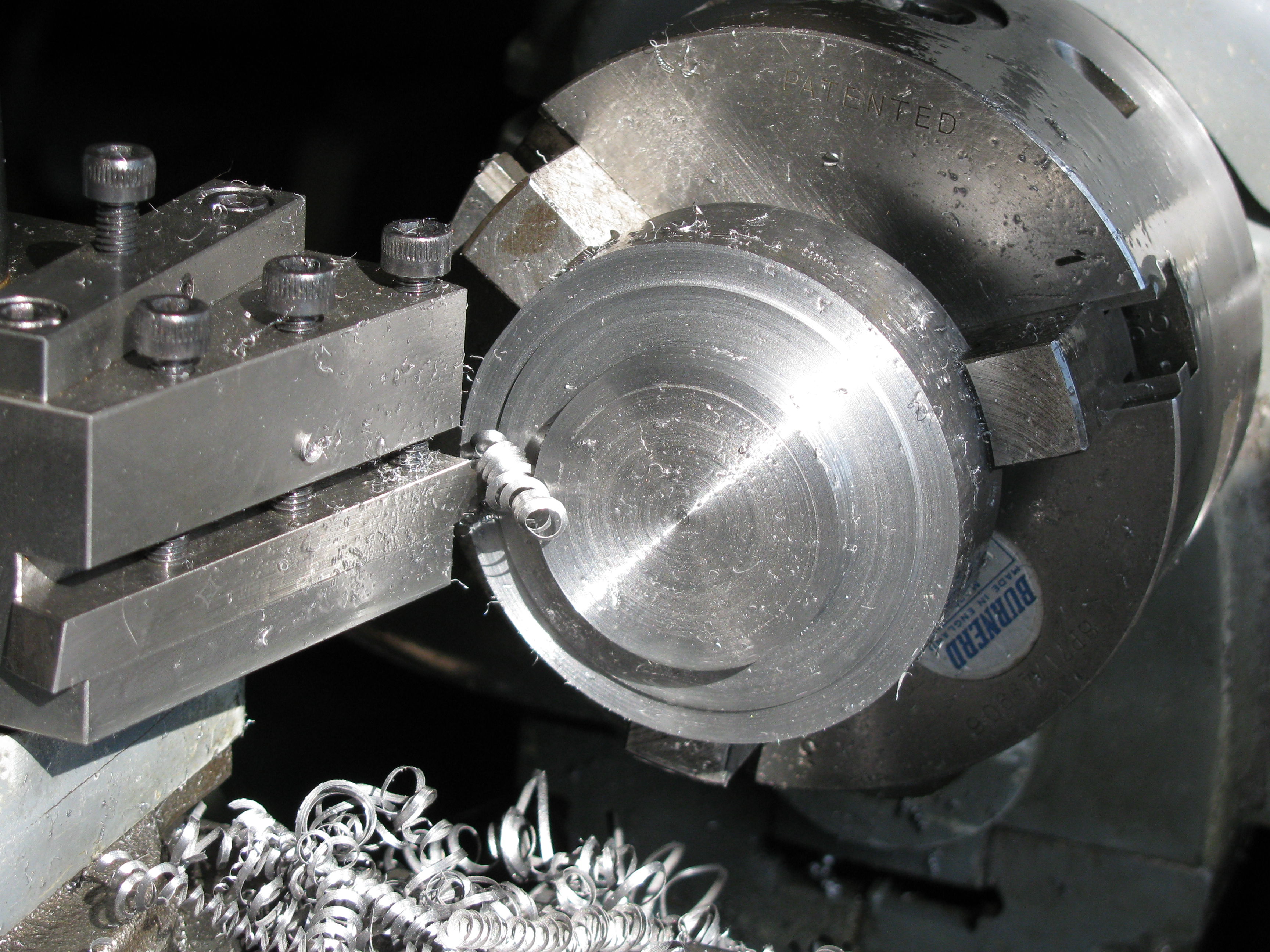
The grooving tool made yesterday worked very nicely doing what I had feared would be a tricky job. I machined the slopes of the pulley groove by alternating the top-slide 15° each way, but keeping the tool square on, easy to do with my indexing toolpost. I generally left about 5 thou all over for finishing on the mandrel later.
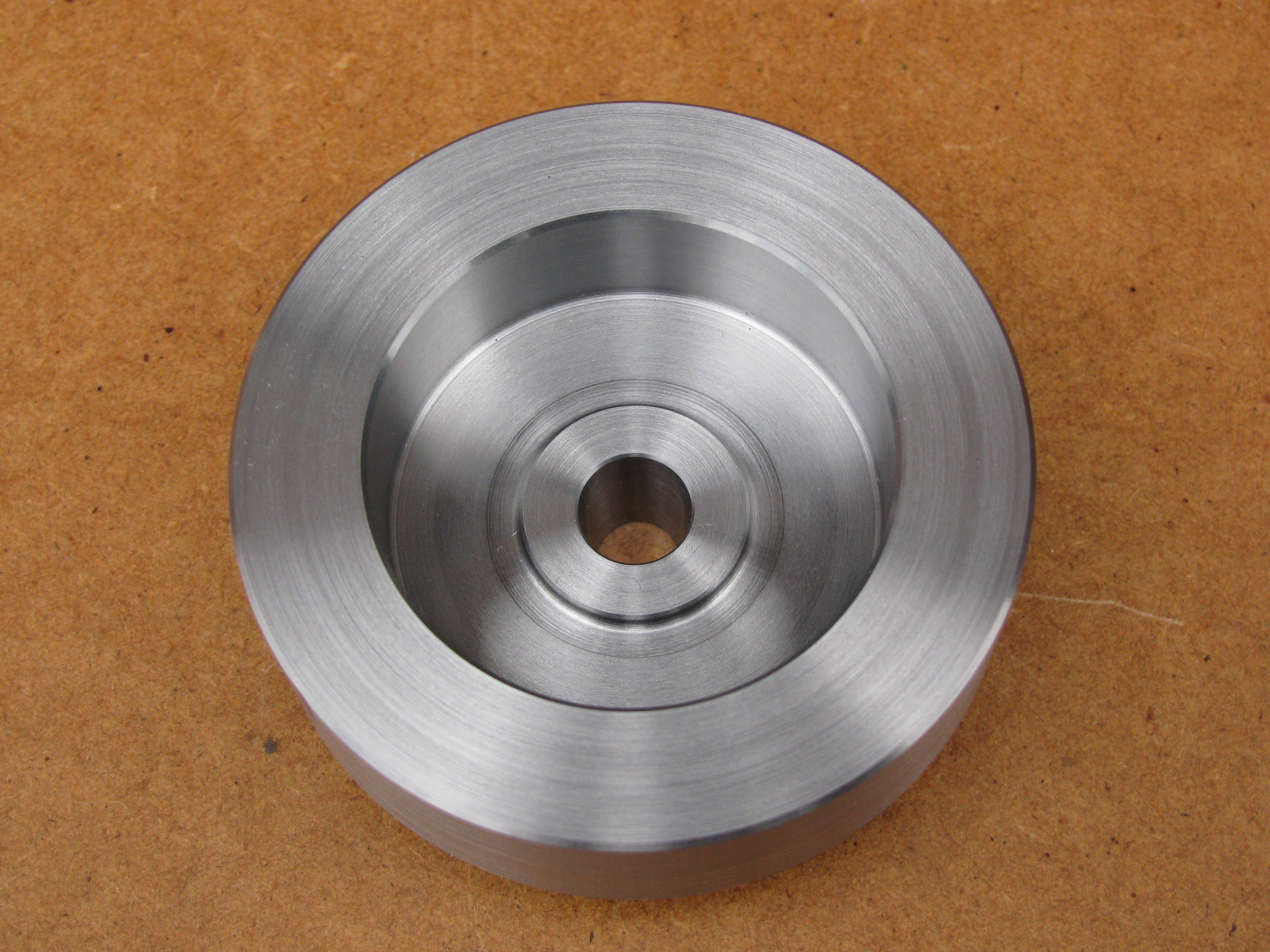
Chucking the other way round for machining the back was made more difficult by the root radius between the flywheel face and the pulley diameter. I had to use shims to pack the face out from the chuck jaws. I could have used soft jaws, and I cannot recall why I didn't. I took enough off the OD, about 10 thou, to clean it up, centred and drilled the hole in 2 stages to 7 mm, roughed out and then finish machined the recess in the back, including the recess in a recess to form the central boss. Rather than grind up a special tool to cut the inside and outside radii, in the manner of a trepanning tool, I used different tools, measuring the depth from the back face on the topslide dial. Again, I left 5 thou on the back face for finishing. I found the steel machined easily to an even tool finish.
For boring the taper I could re-set the taper turning attachment to taper the other way, or I could set the angle on the topside. Either way, the correct angle needs to be set within fine limits and I intended to set it from the taper already machined on the mandrel. I did not want to disturb the position of the taper turning attachment unneccessarily, so I opted to use the topslide. The chuck, with the flywheel still in it, had to be taken off to set the mandrel between centres as a gauge. I managed to get it spot on.
Having put the chuck back in place, I took 4 taper cuts each of 10 thou. (5 hrs)
2011-03-21 - Finishing the bore
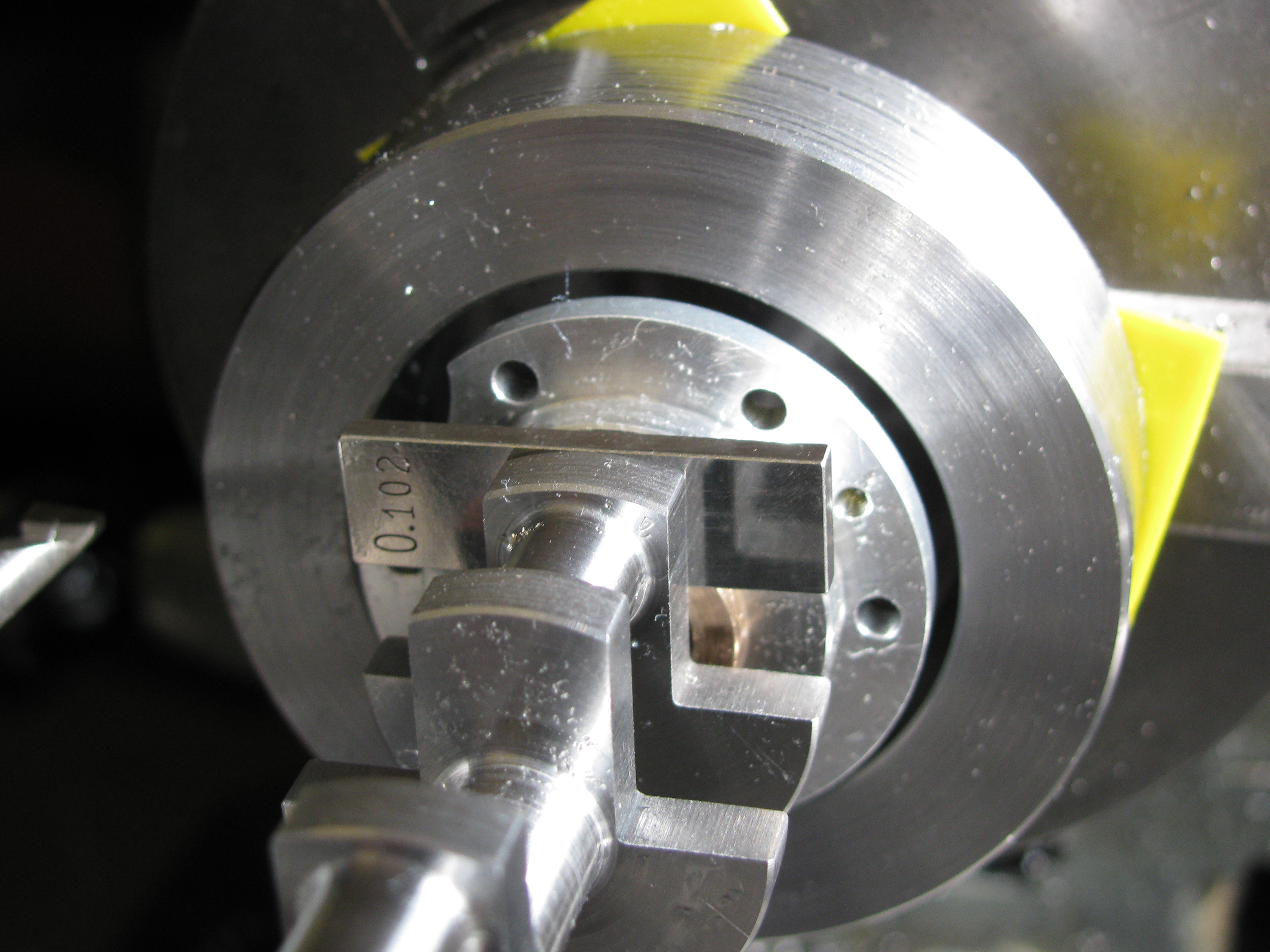
The shaft blues up well in the hole, and seems to fit nicely. After fiddling about with the
5⁄16″ ball to measure the taper, I realised it would be much
better to just try the crankshaft in place, with the font bearing, and working towards the intended
1⁄64″ clearance. I pushed the bearing up against the back of the
flywheel hub, and measured 0.102″ with slips between the inside of the bearing and the crank web.
Further cuts of 5 and 2.5 thou took the clearance, now measured with feelers, to 0.018″. As I would
expect the tapers to bed in a bit, that will do nicely. After lightly chamfering the bore and the boss
face, the job was taken out and tried on the shaft and some clearing up done. (1½ hrs)
.
2011-03-26 - Between centres
This was one of those days when you know something is slightly wrong, but you are not sure what, and it does not seem too bad anyway, so you carry on, hoping it will work out. You ignore, usually wrongly, because it is not forceful enough, the part of your mind suggesting you stop and investigate properly.
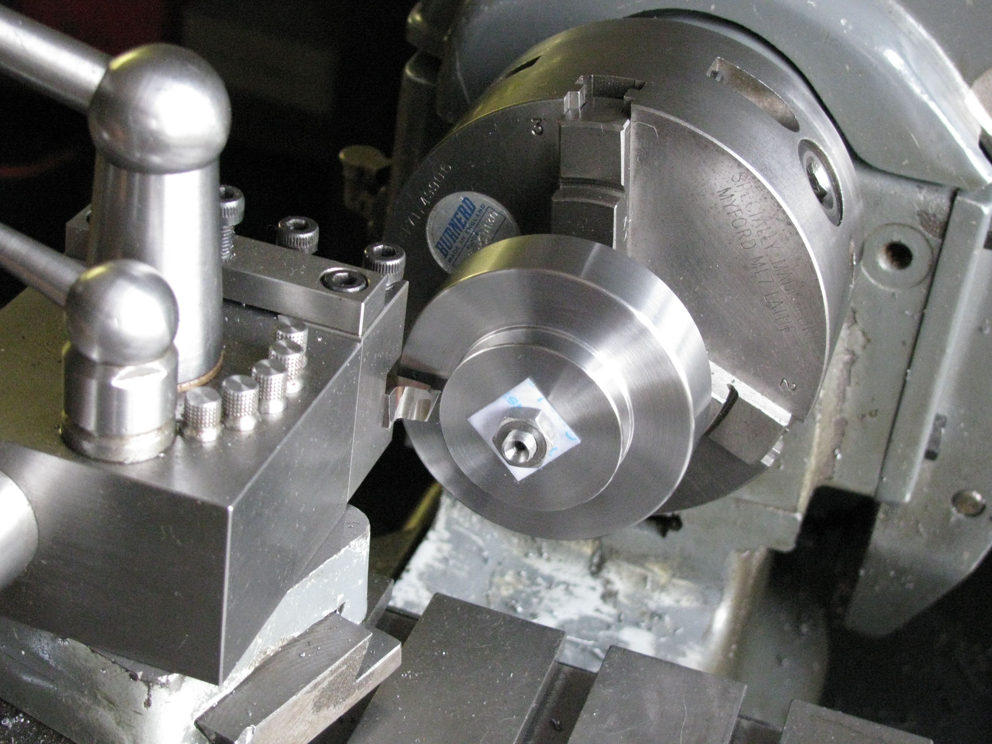
With the flywheel mounted on the previously prepared mandrel, using a sharp tool, light cuts,
and a lowish back-gear speed I was rewarded with a fine tool finish that looked just right.
On the other hand I was surprised how far out of truth the work already done seemed to be.
Well, you can't do anything more accurate than turning between centres, can you, so it must be right.
I cannot remember at what point it became clear that tightening the retaining nut on the mandrel was
throwing it out of true. Possibly when I took it off to finish the front face and then discovered
that the amount of runout changed when I put it back. Anyway, I took the finishing 5 thou off the face,
finished the shoulder, took a cut to true up the OD and another very light cut at 40 rpm, and faced
the back to size. I cut chamfers on the rim, and chamfered the chamfers, as I usually do to make a radius,
then blended them in with a fine file and 400 grit wet-or-dry & paraffin. I finished turned the
the flanks and root of the pulley groove, and put the radii on in the same way. In taking the job out of
the lathe, I put a little mark on the face with the point of the running centre, so I put it back and
machined it out. Finally I turned it end for end to finish the radius inside the rim at the back. Pleasingly,
it proved to be held on the taper too tightly to twist off the mandrel, which needed a tap to remove.
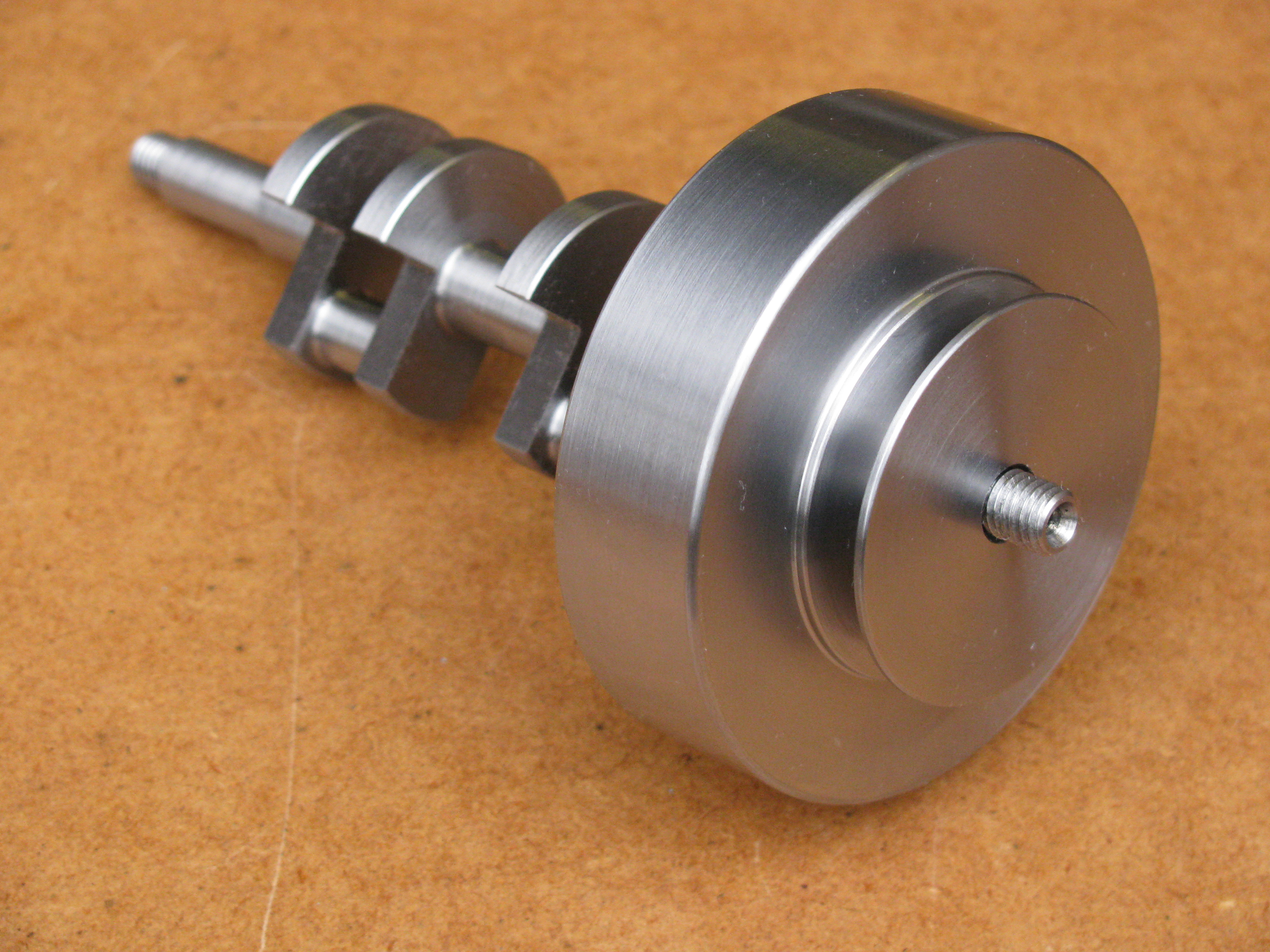
Trying the flyweel and crankshaft together, mounted between centres, it showed a slight visible eccentricity
but no noticable shimmy. (4¼ hrs)
.
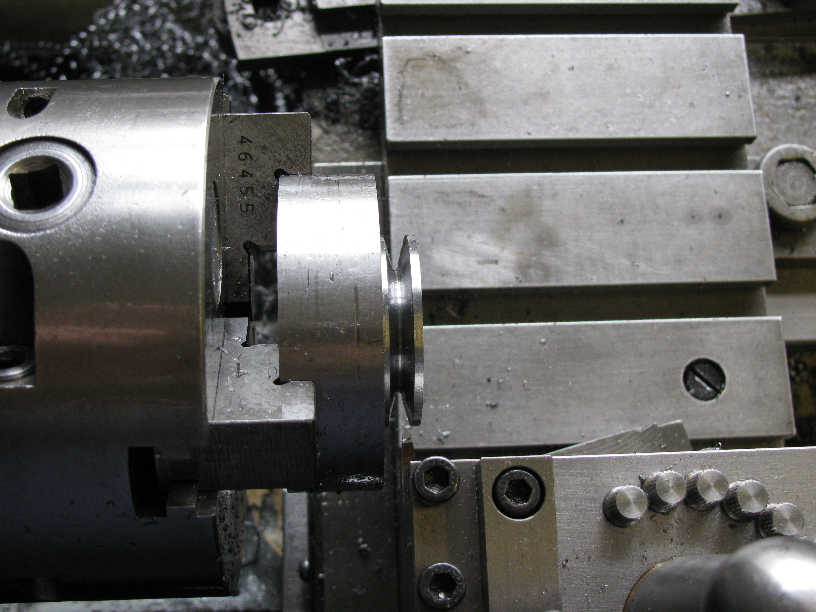
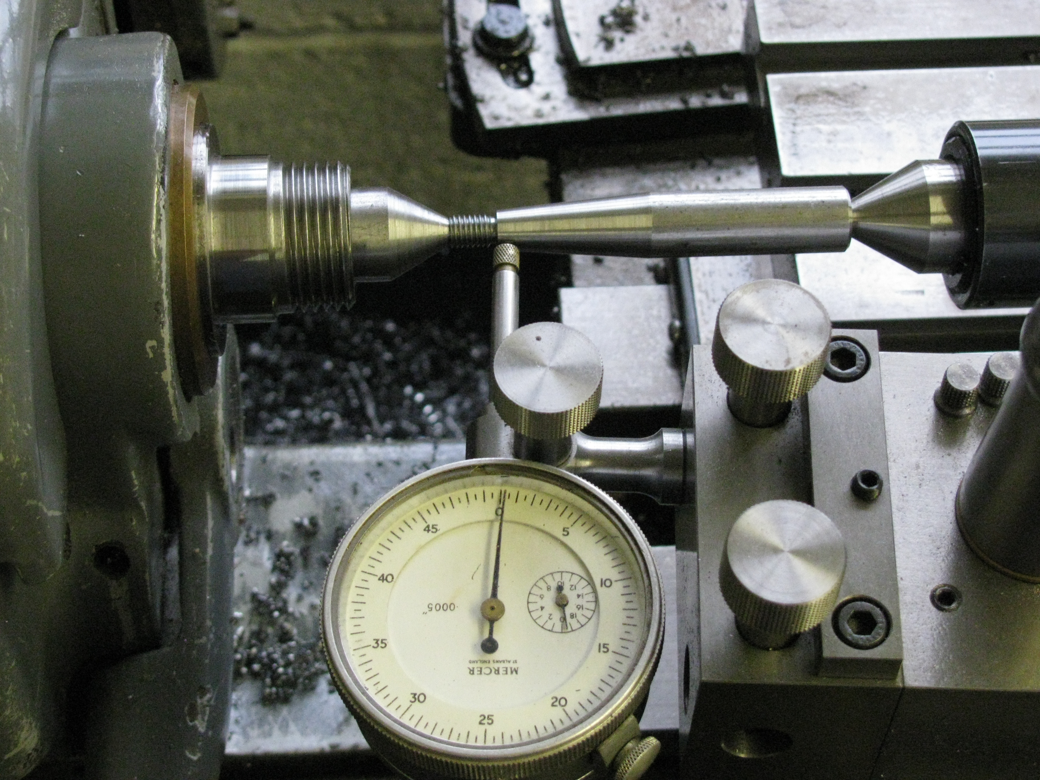
2011-03-29 - Stub mandrel
Unhappy with the idea of a flywheel that was not true, I decided to have another go. I put the mandrel in the chuck, with enough sticking out to be able to get a narrow tool to the back face, and trued up the taper, taking a second cut after finding it did not fit because I had forgotten to get the tool accurately on centre height. The bore blued up nicely, but the flywheel would not wring on as before, so I held it on with a nut (with a card washer under it). Clocking up, I found 2½ thou runout at the flywheel nose and 1 thou at the back, which tends to support the idea that the nut was bending the nose of the mandrel when mounted between centres. Using it now as a stub mandrel, without tailstock support, would not give rise to the same problem. With this set-up I fully re-machined the whole of the exterior, taking off as little as possible. This means the dimensions are all a few thou off, and the pulley groove a bit wide and deep, but it does not have to mate with anything, so it does not really matter. (2½ hrs).
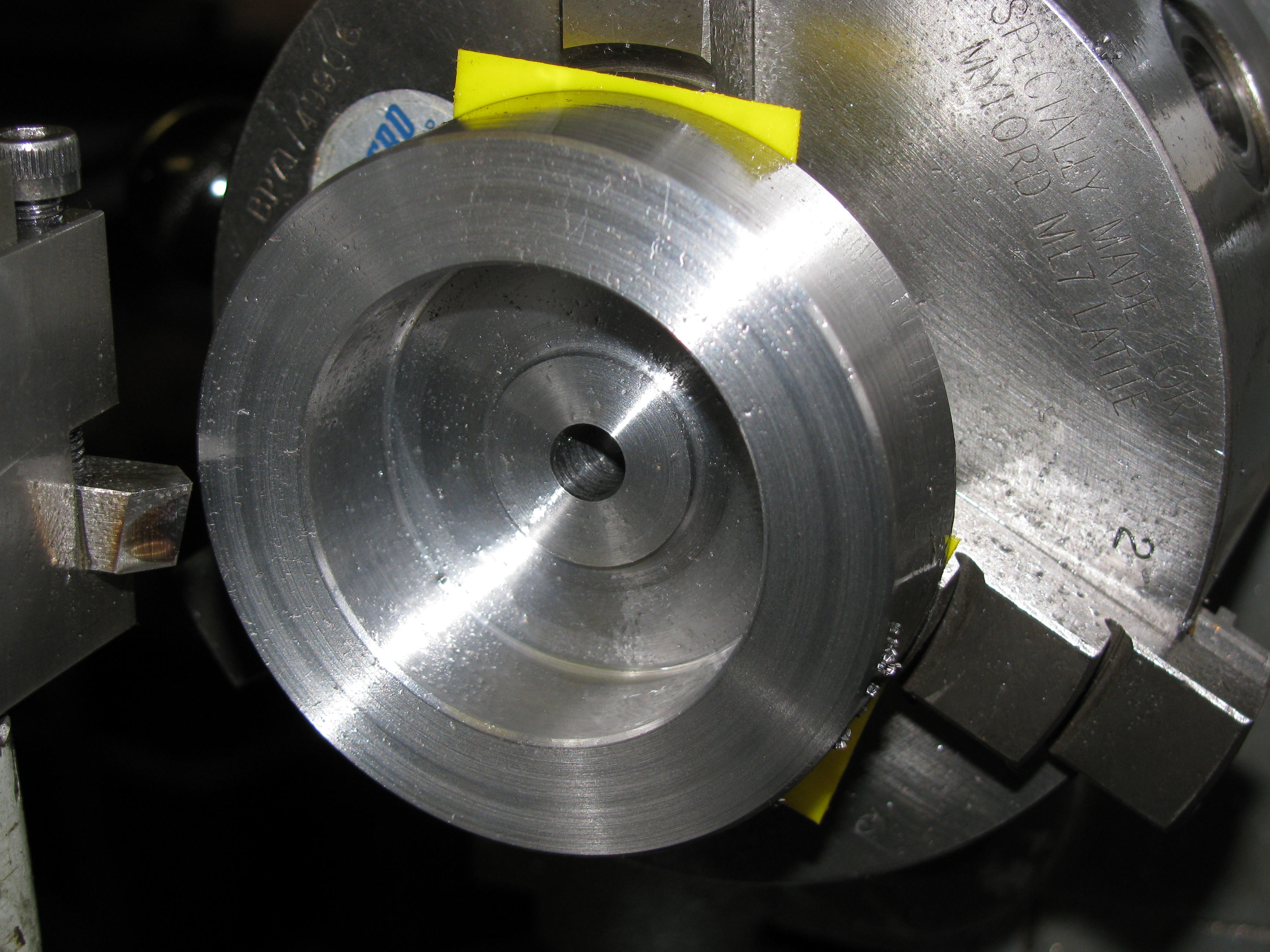
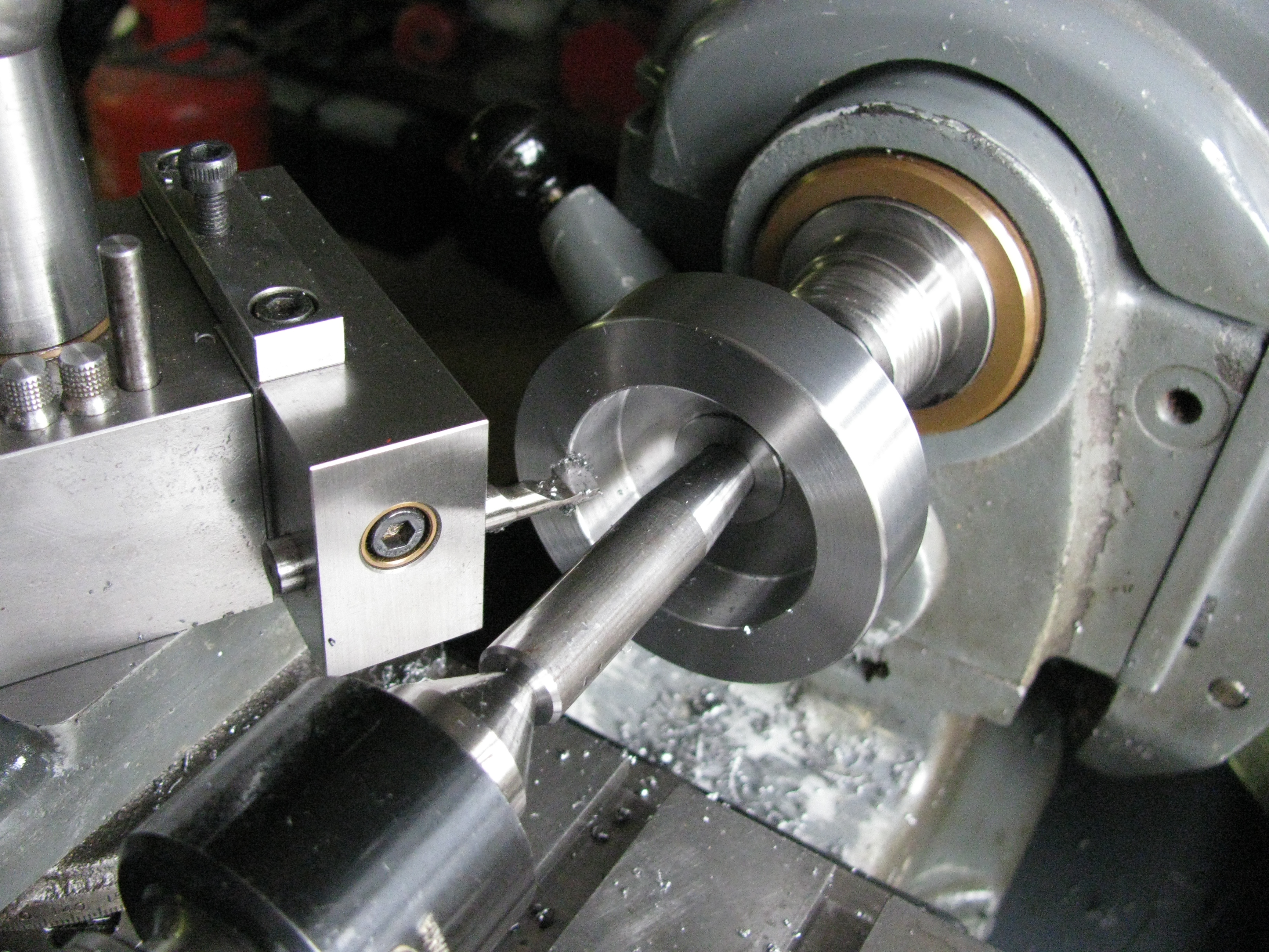
2011-07-22 - Drive holes
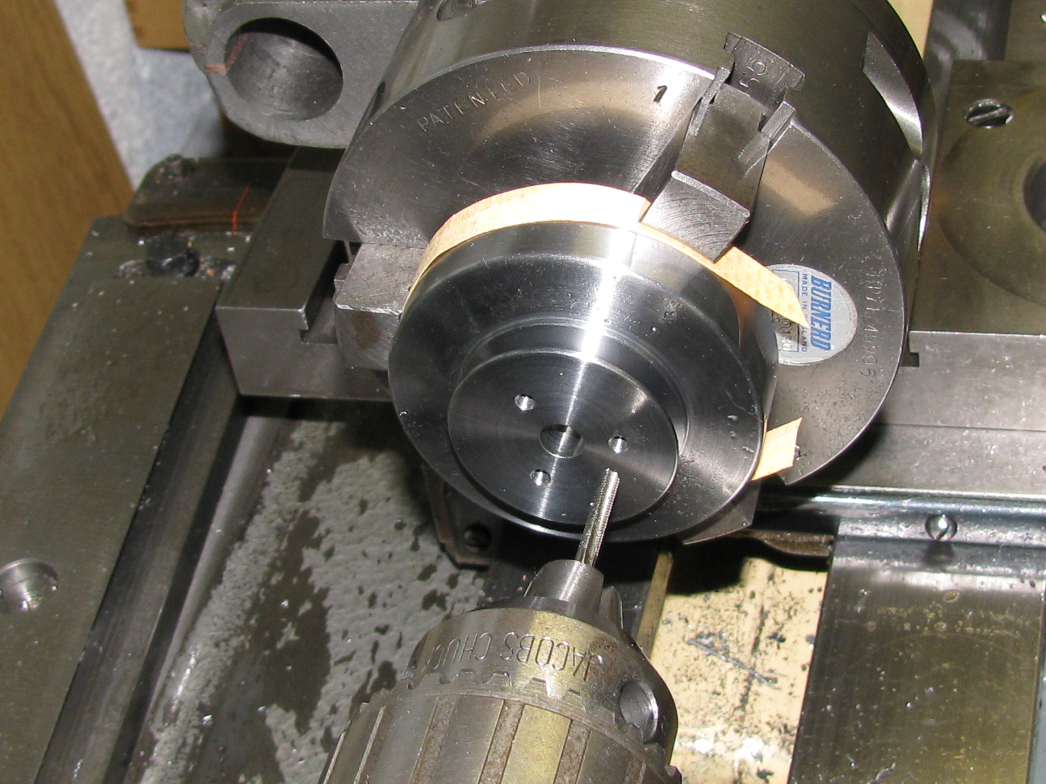
Now that I have drawn a flexible coupling to take the drive from the engine, I can put some holes in the flywheel to take the drive studs. Using the outside jaws to hold the flywheel (with paper softening, obviously) I adjusted the Griptu chuck to get it running true and then transferred the chuck to the dividing head on the saddle block. I drilled, counterbored, tapped and lightly chamfered three 5BA holes on ¾″ pitch circle. Flywheel done. (1½ hrs)
.