
Tools
Here are some rather random details about some of the tools and jigs I have made while making the engine. Some are general purpose additions to the workshop facilities, and some are very specific to the Seagull project. The amount of detail I have recorded in making them varies enormously.
Cylinder head bolt drilling jig
2014-01-21 - Starting the drilling jig
I cut out a piece of 3⁄16″ mild steel for this jig and milled one side. (1 hour)
2014-01-22 - Drilling jig milling
Today I finished milling the main plate. By compensating for the fact that the cross-slide is not exactly square to the bed, I managed to get the plate pretty accurately square, with the sides parallel to 0.001″ and a maximum of 0.002″ undersize. I cut the side and end fences from some old and rather rusty 15mm by 3mm mild steel and milled the pieces to length, then drilled and tapped the 6 BA fence holes in the plate and finally drilled the clearance holes in the fences.
There will now be an interlude while a second-hand milling machine is acquired, stripped, cleaned-up, repaired and re-commissioned. (It still needs quite a bit work, and a paint job, but I want to get used to it for a while and then decide exactly what else needs doing). Then the first job was to make the base for a DAG Brown pattern Small Drill Sharpening Tool. (3¾ hours)
2014-03-20 - Preparing the drilling jig
After a discussion on a couple of forums I decided that the drilling jig would be most accurate if the holes were made for hardened bushes, one for tapping size and one for clearance size. I also decided that if I was going to all this trouble I should position the holes using the toolmaker's button method. I ground up a small boring bit for the purpose and then stamped the top side of the jig plate. (½ hour)
2014-03-23 - Drilling the drilling jig
I marked out the initial hole positions as honed the sides of the jig to remove the 0.001″ taper and to improve the squareness. I drilled the holes on the milling machine. I think the Y-axis dial moved, as some of the holes ended up a mile out; a good thing I decided on buttons for final position. I tapped the holes, set the button for the first hole using slip gauges and the surface plate in the usual way, and set the job up on the lathe faceplate with the button clocked true. I opened the hole out with a 5⁄32″ slot drill to avoid following the tapped hole, and then bored and reamed the hole 3⁄16 ″. The boring tool evidently was not right as it would only cut on the outfeed. I repeated the process for the second hole. (3½ hours)
2014-03-24 - Boring the rest of the holes
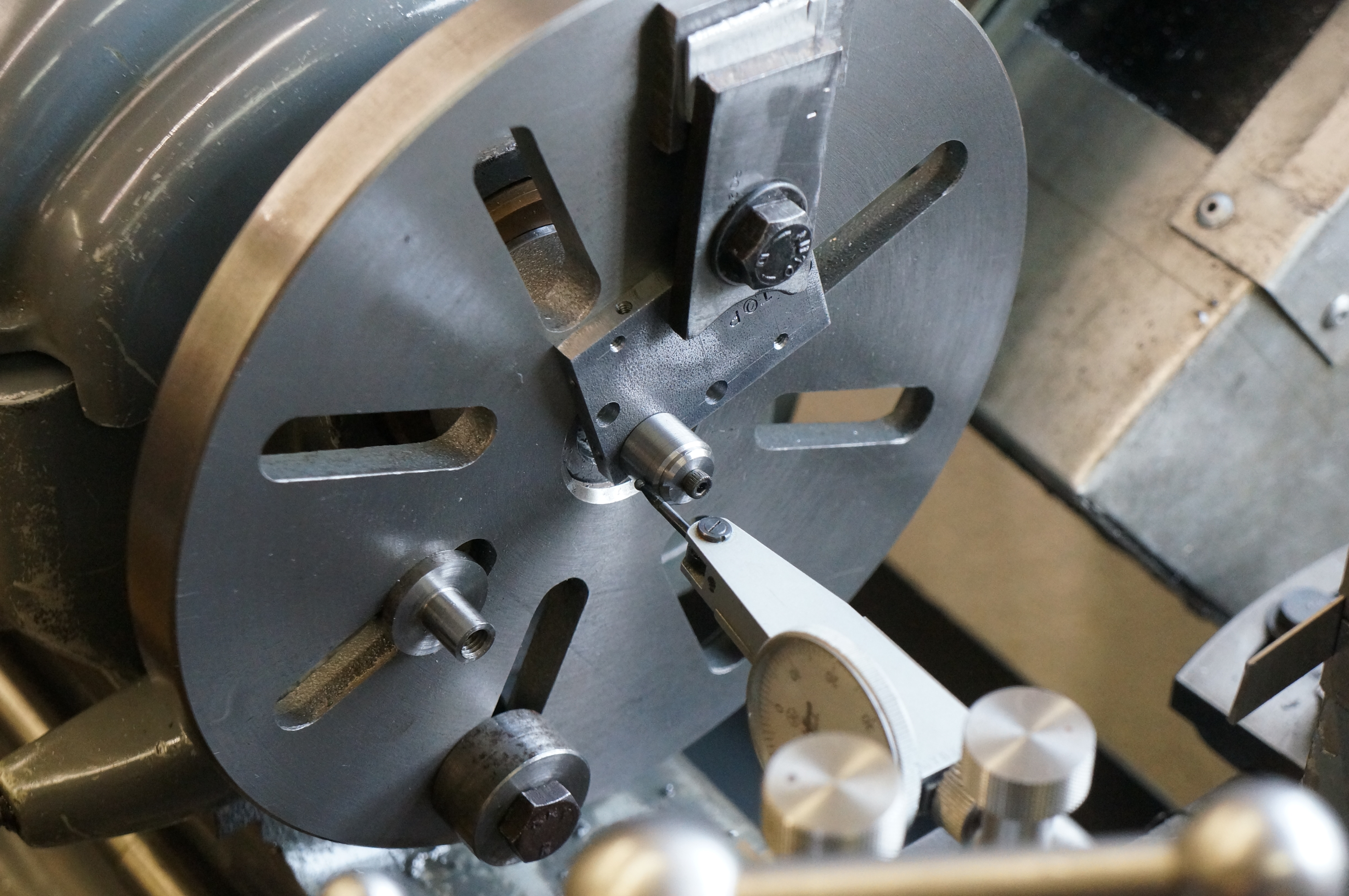
Today I bored all the remaining six holes, setting up each one with the toolmaker's button on the surface plate and then re-mounting on the faceplate. Note the stub is still in place on the faceplate for mounting the con-rods for machining the little ends, as I have yet to make a satisfactory job of them. (4 hours)
2014-03-25 - Re-working two holes
I had forgotten that I intended to move the holes by the combustion chambers out a bit. There is only room for another 1⁄64″ between centres, but even this much will make a difference. I had to set the toolmaker's button with a washer and nut behind. I opened the holes to a little over 7⁄32″ to completely re-machine the old misplaced hole. I will have to either sleeve them back down to 3⁄16, or make special drilling bushes to fit.
Later, I machined the drilling bushes from silver steel, one drilled 2.2 mm for tapping and the other 2.8 mm, which is nominal size for 6-BA. I will try drilling the clearance holes nominal size first as that will give the best alignment of the parts, short of dowelling, but if the drilling is not perfectly accurate I may have to open the holes out a little to provide enough clearance. (3¾ hours)
2014-03-28 - Completing the jig
The first job today was to harden the drill bushes. I did not temper them. Next, I made mild steel sleeves to reduce the size of the two repositioned holes to fit the drill bushes, parting them a little over length. I Loctited them in place and filed the faces flush with the plate, then put the 6BA tap through the side-plate fixing holes a second time, as opening out the drill bush holes had slightly broken into the tapped holes. (1½ hours)
Coolant pipe soldering jig
2014-09-22 to 27
I am not going into the details of making this jig. It is just some pieces of mild steel flat bolted together. Its construction and use will be seen here. I later added pieces to adapt it for soldering the silencer body.
Cylinder Lap
2014-08-25 - A lap
I tried making the business end of a lap from a piece of 1″ × 1⁄8″ copper strip annealed and wrapped into a circle. I messed about with machining it but the result was not much good. (1¼ hours [wasted])
2014-08-29 - A second lap
Having begged a short offcut of 7⁄8″ copper tube with a 1⁄8″ wall, I bored it, rough turned the outside and drilled a matrix of holes.
2014-12-10 - Slitting the sleeve
With a 4″ saw, I was just able to slit the sleeve in one simple set up (without slitting the stud up the middle too). I cut a length of ¾″ steel bar and turned it to the diameters for the head and tail ends.
2014-12-11 - Slitting the shank
With the 4″ saw again, and another slightly hairy set up, I slit the shank. Normally I run slitting saws the other way round and with the lathe in reverse. This means that if anything untoward happens the clamping collar will immediately unscrew and so stop driving the saw. With this job it kept unscrewing anyway, as going backwards, any deflection of the work was pulling onto the saw. I could have remounted it above the spindle, but decided to risk running forwards for once. The slit bar has opened out about 4 thou. Finally I milled an enlarged slot at the root of the slit, intended to ensure it flexes in the right place.
2014-12-16 - Drilling
Putting retaining screw holes in both parts.
2014-12-20 - Final details
Adjuster holes drilled and tapped. Retaining and expander screws cut down to fit. I tried turning the sleeve in situ but getting a nasty surface, so I annealed it, as I don't think I have done so yet. With tailstock support and a slow speed the finish is much better. I turned it to fit in No. 1 liner.
A hollow centre
2015-05-30 to 06-02
Something is needed to support the ends of the valve stem shanks for turning these long, slender items. The diameter is too small to centre drill. The answer is to put a 60° cone on the valve stem, and use a hollow centre. I decided to make a simple rotating one using a No 2 morse taper blank arbor. This is turned to 7⁄16″ for a 1¼″ length, drilled, and bored for a bronze bush. The interchangeable centres are made from ¼″ silver steel and run in the bush, which is finish bored after Loctiting in place. The end thrust is taken by a single ¼″ hardened steel ball sitting in a pocket at the bottom of the hole. A small radial oil hole is provided, which also allows air in and out when swapping the centres.
The big one - A Cam Grinder
2016-11-12 - The finished grinder ready for use
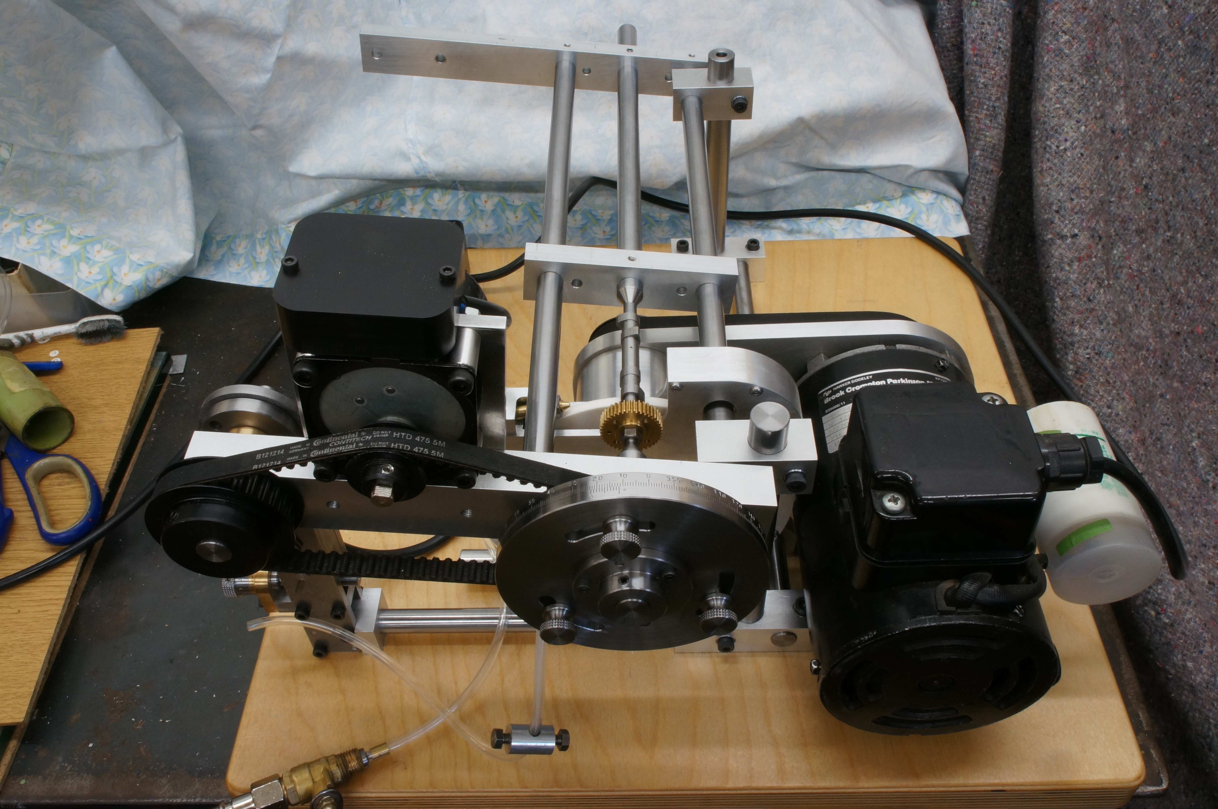
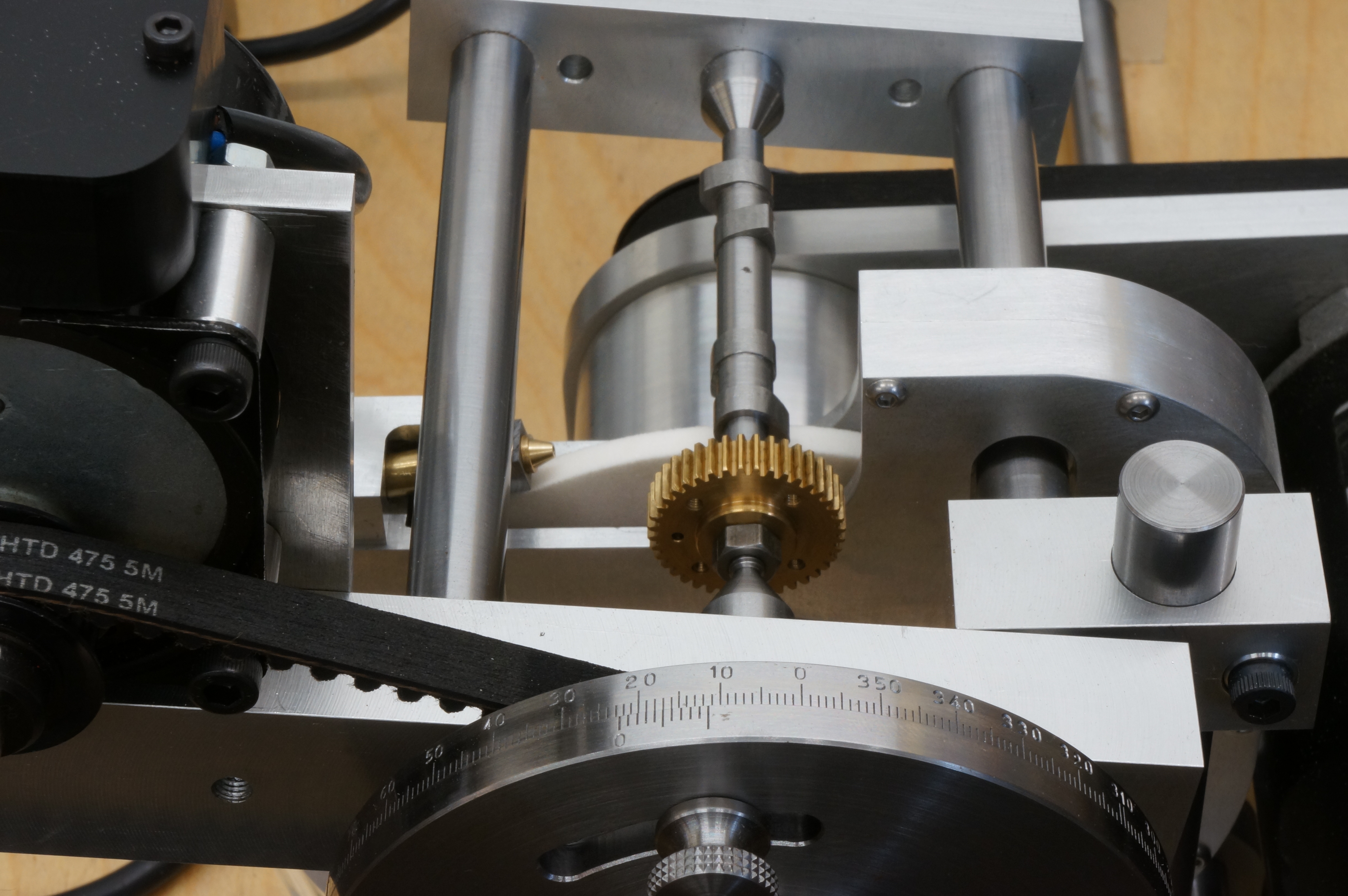
I am not going say much about the construction of this tool, other than that it was an interesting but quite straightforward job. Weirdest was machining the wheel guard from solid.
.
A taper reamer for the carburettor choke
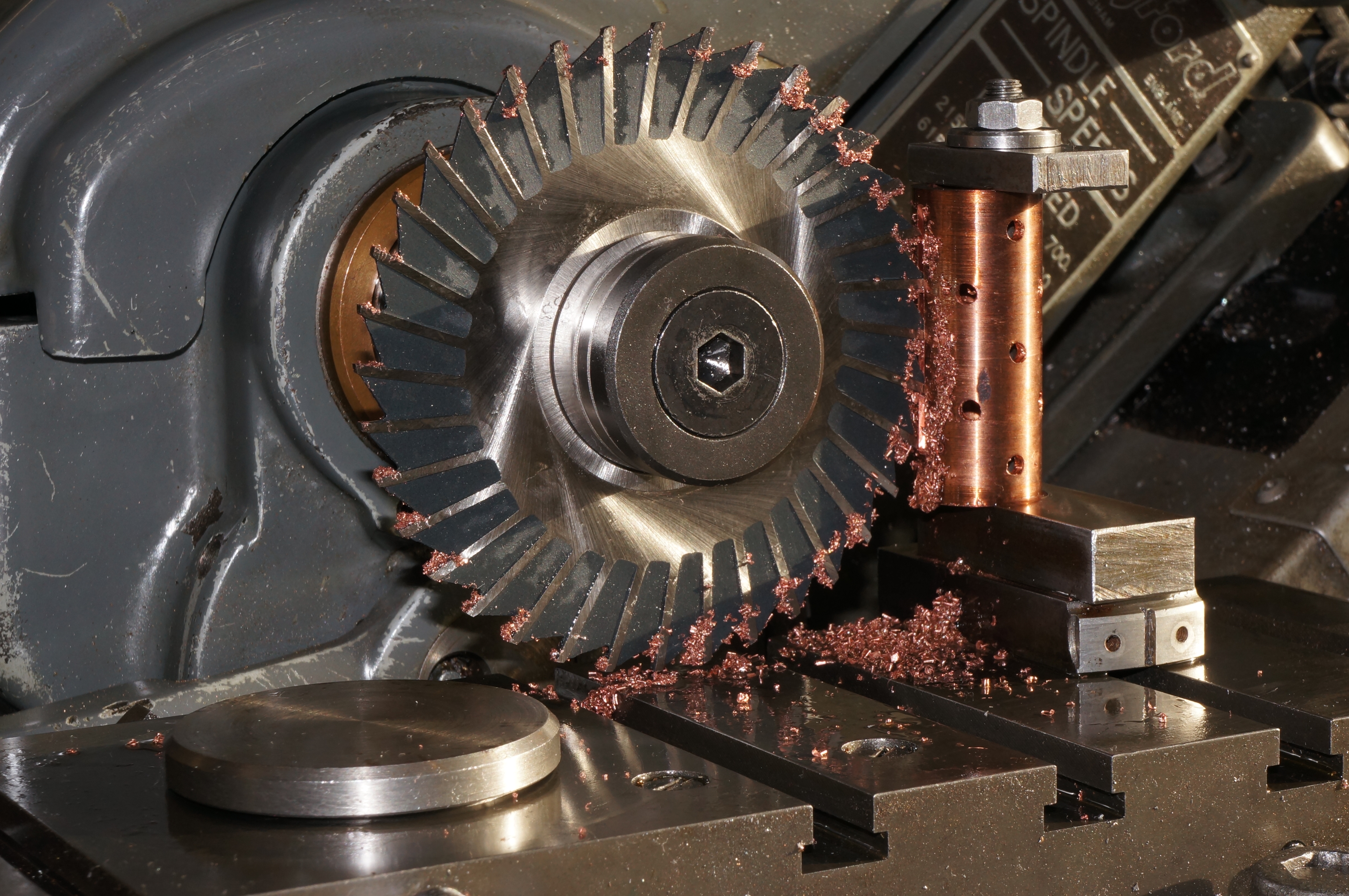
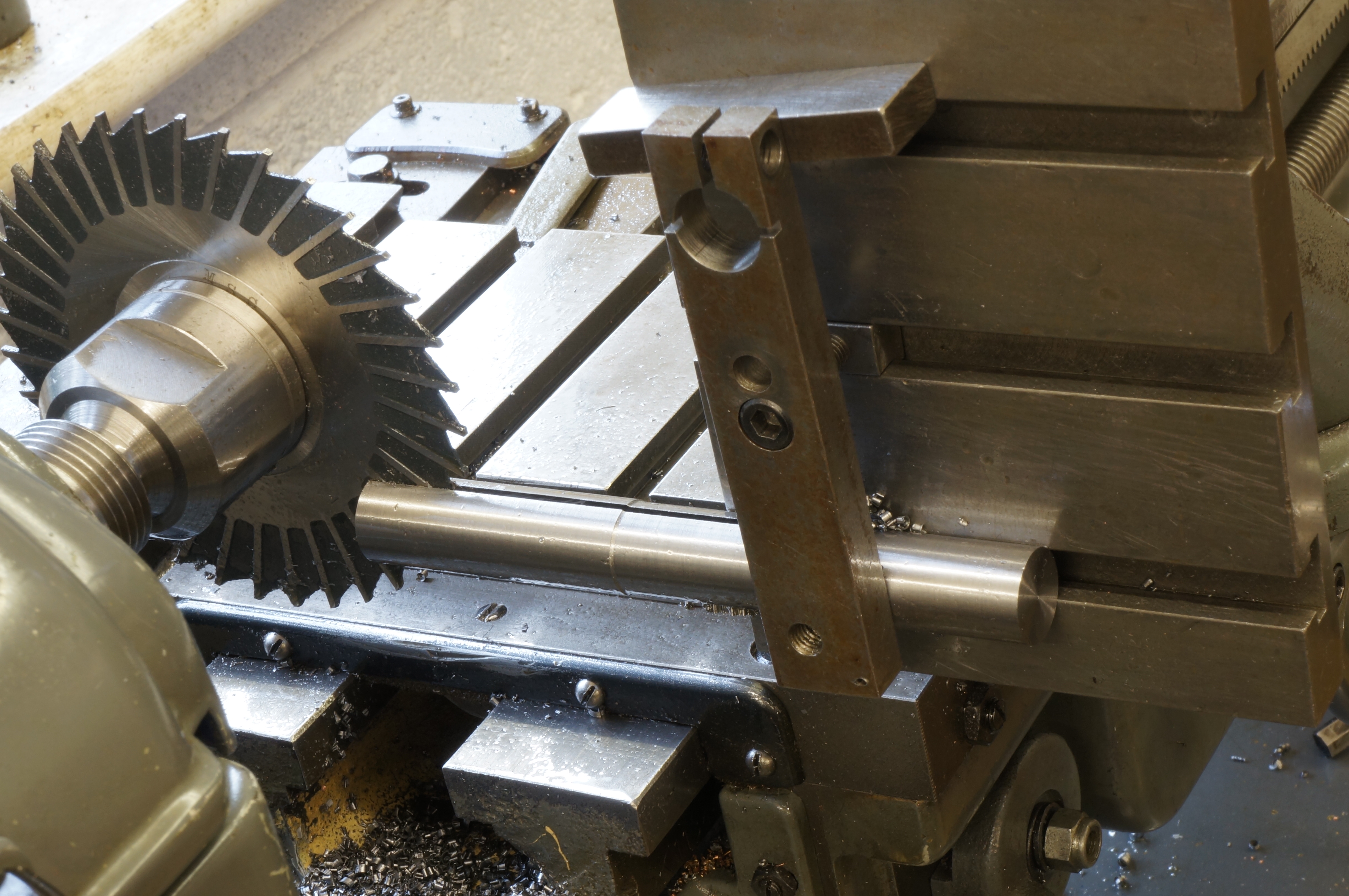
2019-04-01 - Milling the flutes
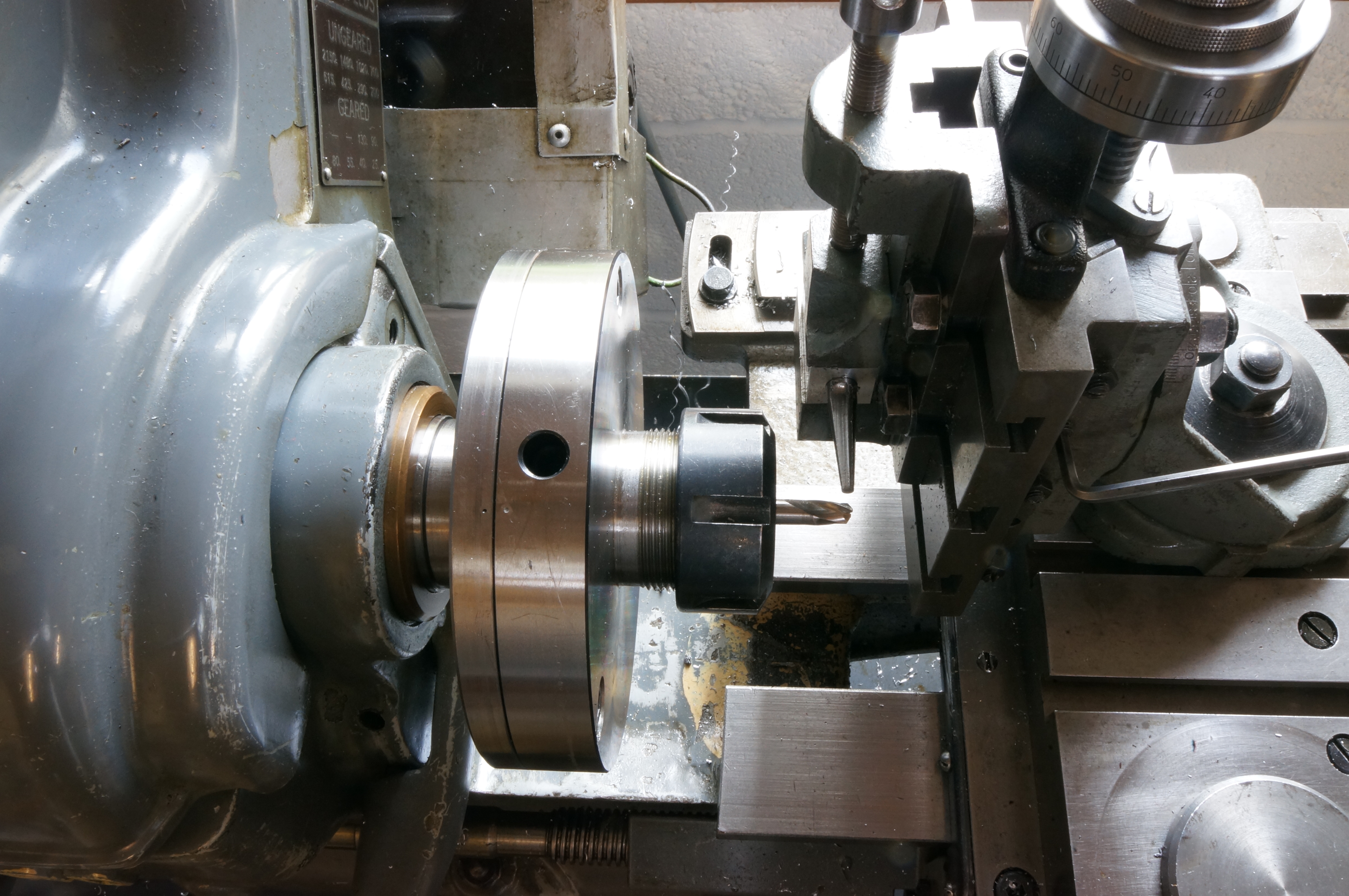
Designed to be similar (in the strict geometric sense, ie the same shape at any section, but a different scale) the flutes are milled at a compound angle. In this case they worked out at 2.8°, set with a vernier protractor, to give the tapering tooth depth, and, more critically, 0.9°, set by trigonometry with DTI to give a consistent rake angle.
.