
Main Bearing Housing
Westbury's drawing of this shows the nose, even at its thickest, thinner than the bush it is supposed to support and tapering almost to nothing. I cannot see why. I have drawn it substantially thicker, with a coned section to transition the profile to the flange and to comfortably accommodate the oil way. Equally, I cannot see any good reason for making the locating spigot 3⁄16″ long at this end, necessitating a recess to accommodate the bearing flange, while at the timing end the spigot is 5⁄32″ deep and the bearing flange sits proud. I have chosen to make this end the same as the timing end. The spigot diameter is reduced by 1⁄16″ to 11⁄16″, and the fixing holes pitched on a 1⁄32″ smaller diameter, to allow more metal round the holes. I have also shown a cut-away for the camshaft bush, and have offset the holes 10° to dispose them equally about the cut-away, and added a couple of 8BA tapped holes for jack screws so the housing can be removed without marking it.
A piece of 1½″ alloy bar is supplied for this part. As it needs to be cleaned up to look right the OD will inevitably end up a few thou under nominal. The machining sequence can be tackled in a number of ways. In any case, the heavy roughing cuts on the exterior should be done first, but should these unimportant externals surfaces be finished at this setting, or as a third op? Will the bush be pressed in or fixed with Loctite? If so, should it be finish bored at the same setting as the spigot diameter and flange face are machined, to maximise geometrical accuracy? The last is a no-brainer — it can be, so it should be. I may well want to lap the bore, it is too important to leave to the uncertainties of reaming, so a lap needs making (and trying out) first. Loctite seems fine for retaining the bush. I have a bottle of 641 bearing fit. The order of machining boils down to gripping in a ring or soft jaws for the second op, or chucking and finishing the outside on a stub mandrel. I will go for the first option, and as I have soft jaws, that is the way to go. A fairly narrow ledge on the jaws will allow transfer to dividing head for drilling, tapping and machining the cut-out. Paper protection will be needed, even with 'soft' jaws.
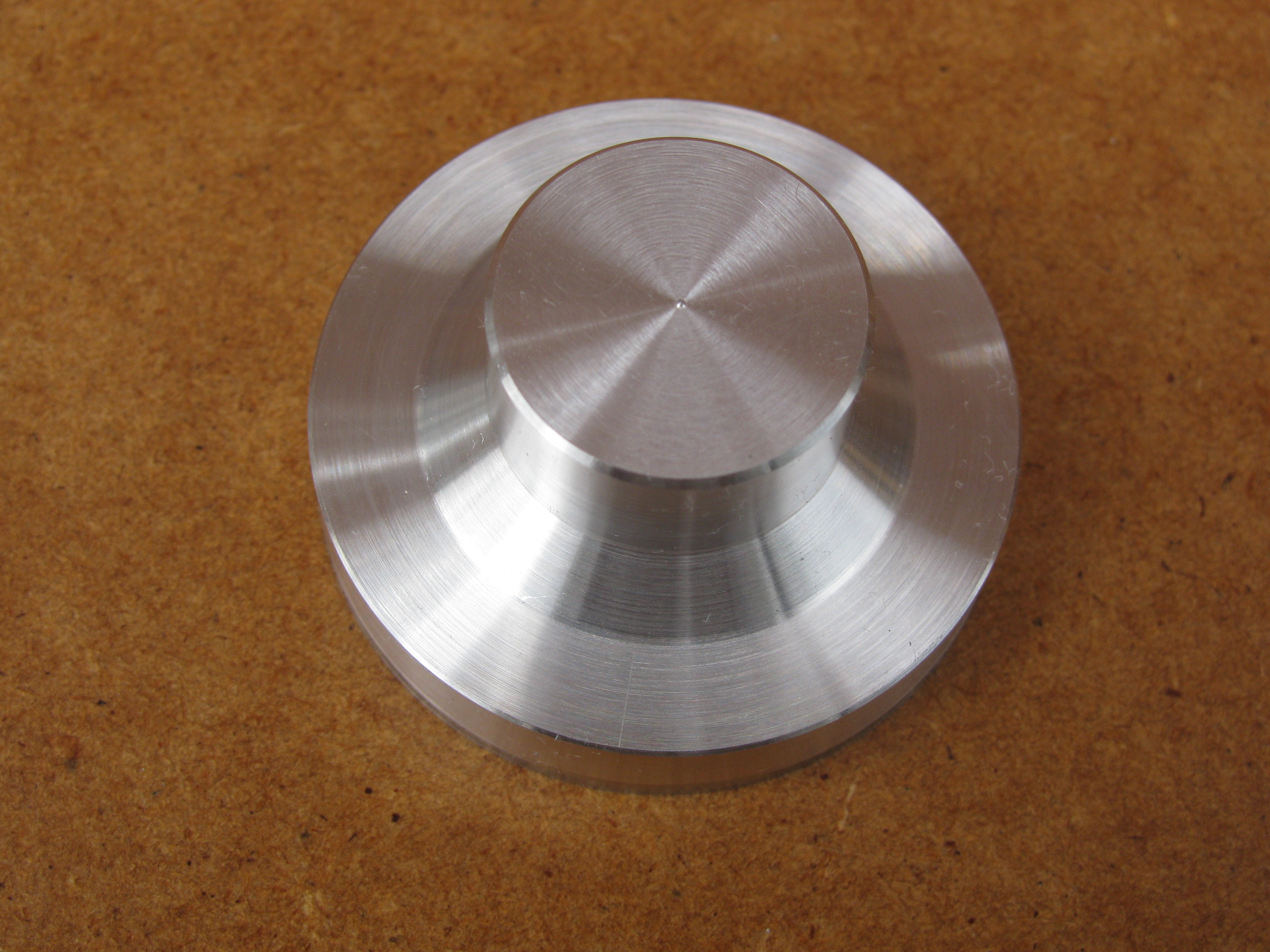
2010-08-23 - External shape

After rouging out yesterday, I completed the exterior to my modified profile. With the topslide set over and the slope length calculated, I finished the cylindrical part, the cone and the face, feeding outwards, in a continuous pass. The resulting distance from the outer end to the flange was 0.499″, so I felt pretty smug. By comparison with the castings, the surface is very shiny. If it were not mostly hidden by the flywheel I would be tempted to sand-blast it. Finally I parted it off from the chucking piece, and moved on to the timing case. (1 hour)
.
2010-10-22 - From the back
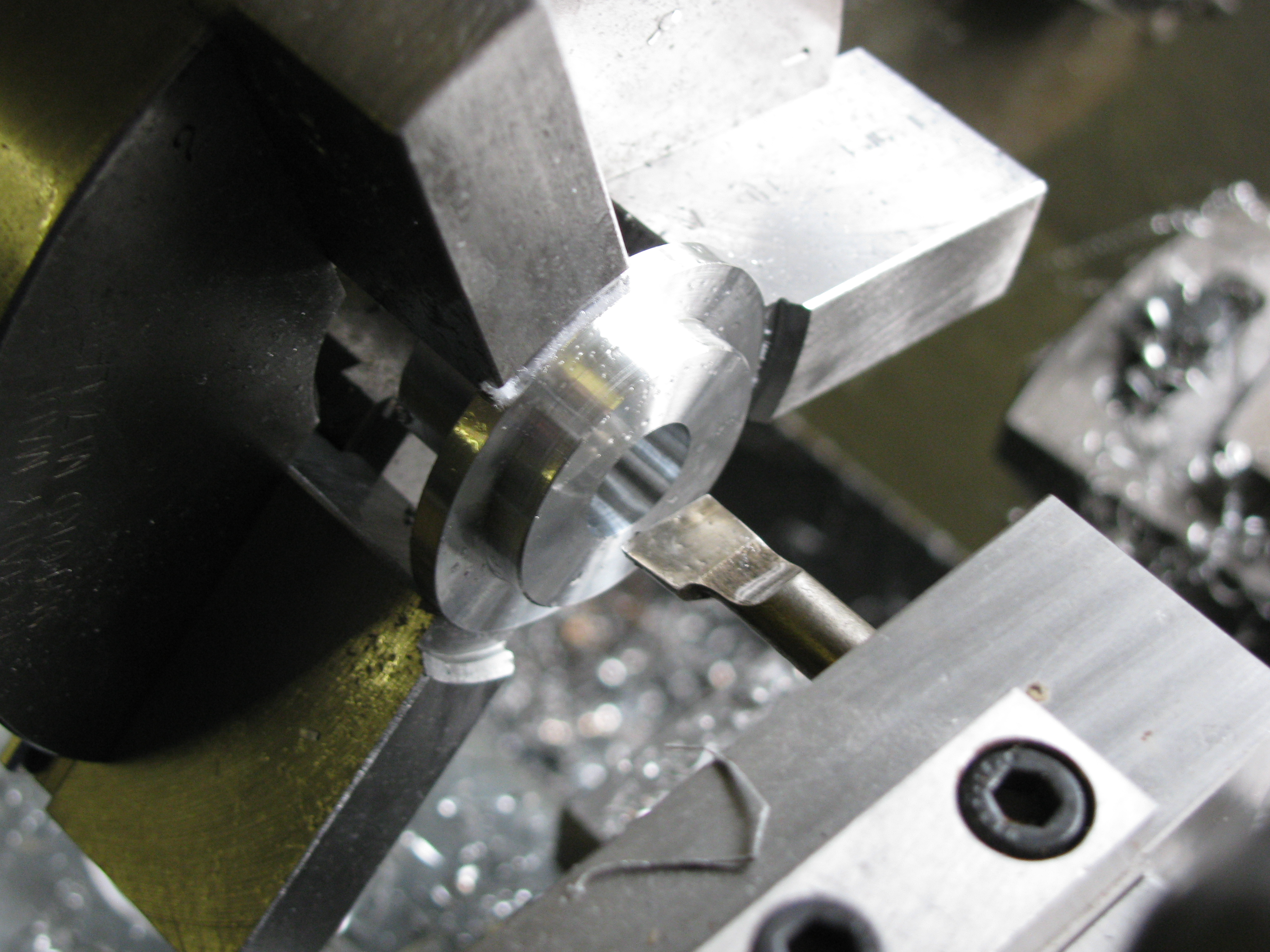
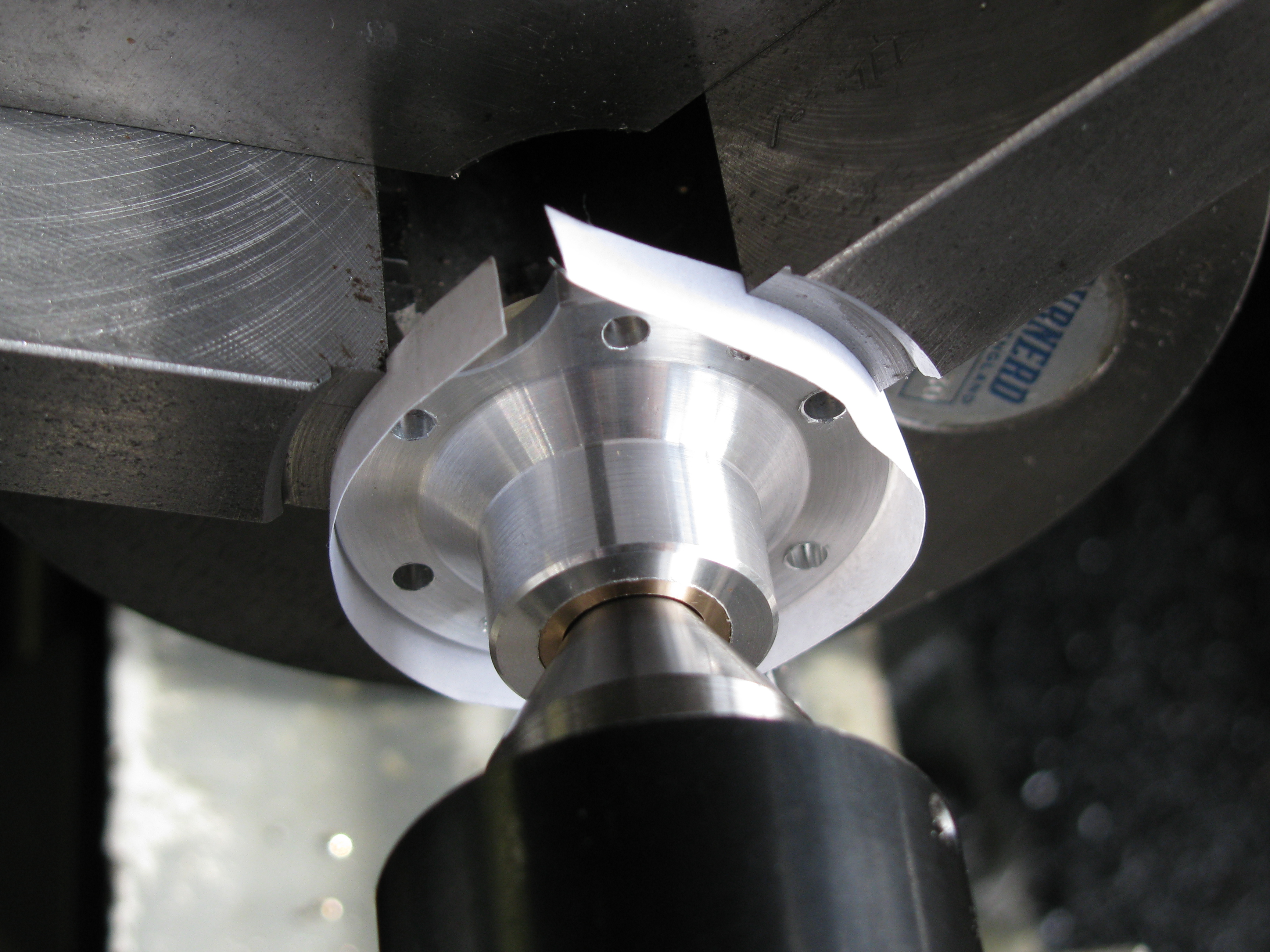
Not long ago I bought two sets of soft jaws for my 3-jaw chuck, and this is the kind of job where they really make a difference. The only other good way to grip this part truly for second operation turning would be to make a split clamping ring. With an offcut gripped below the face of the jaws, I cut a shallow seating, making sure to slightly undercut the corner. I gripped the flange with a ring of notepaper round it to protect the finished periphery, and tweaked the Griptru chuck to get it running dead-on.
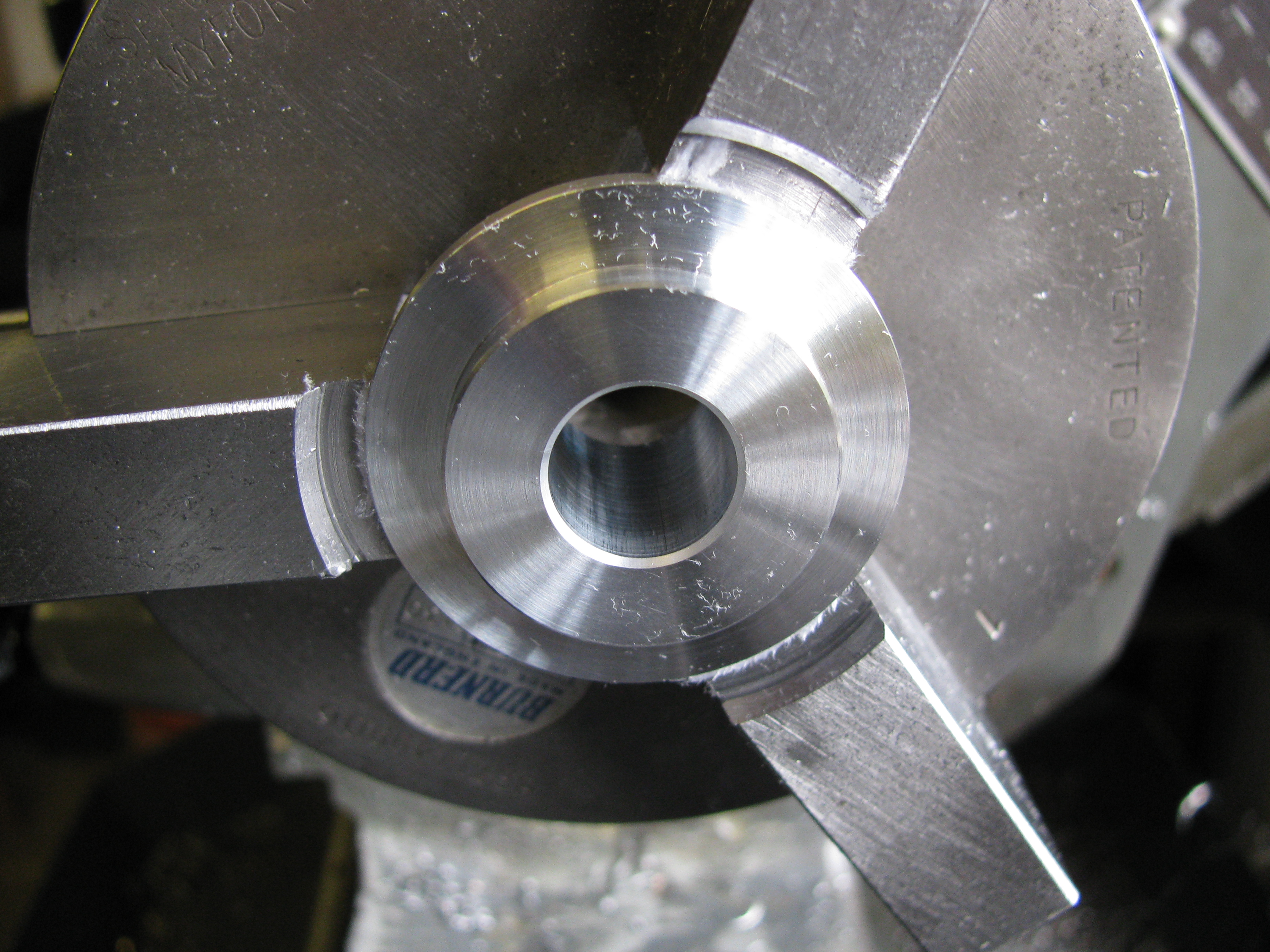
I drilled the central hole out to 11 mm, faced to about a thou over size, and turned the locating spigot to length, and to diameter plus about 0.0001″. Boring the hole, at +0.0005″ the bearing bush would not go in, but taking another cut at the same setting gave +0.001″, and seemed pretty parallel. The bearing slipped in with a little bit of shake detectable, ideal for Loctite. After putting a small chamfer on the OD, a slightly bigger one on the spigot, and a good 1⁄32″ one in the bore, I took a further shave off the first part of the bore to accommodate a slight step on the OD of the bearing bush. I cleaned everything up and glued, again using the tailstock centre to apply a little pressure while curing.
I gave it half an hour to go off and then faced the bearing bush to length, more by luck than judgement, having another near-miss with the depth micrometer. Again, I took about ten passes to open out the bore. For some reason I can turn almost anything nicely parallel on the outside, but I can rarely get bronze bushes parallel in the bore. Having got this one to 0.3745″ at the outer end (inside on the finished engine) and about 0.374″ at the smallest, I decided to leave the rest for lapping. A whole thou is quite a lot to expect to remove by lapping, but I did not want to risk taking any more off. I put a 17 thou chamfer cut at 45° and then two more cuts halving the angle each side and making three lands of equal width. The radius will be scraped to fit the crankshaft.
Without taking the job out of the chuck, it was set up on the dividing head, on a vertical slide for drilling. As usual, I clocked the bore to get it concentric with the lathe spindle, and used the cross slide dial to measure the radius for the holes. I drilled the six clearance holes, and put in two holes to be tapped for the 8BA forcing screws. At a radius again set with the cross slide, I roughed out the cutaway for the camshaft bush with a 5⁄8″ slot drill, and took a further 15 thou with the boring head. The cutaway is not exactly equidistant between fixing holes, as I offset them by 10° while the camshaft hole is at 41° from vertical, relative to the crankshaft. (5 hrs)
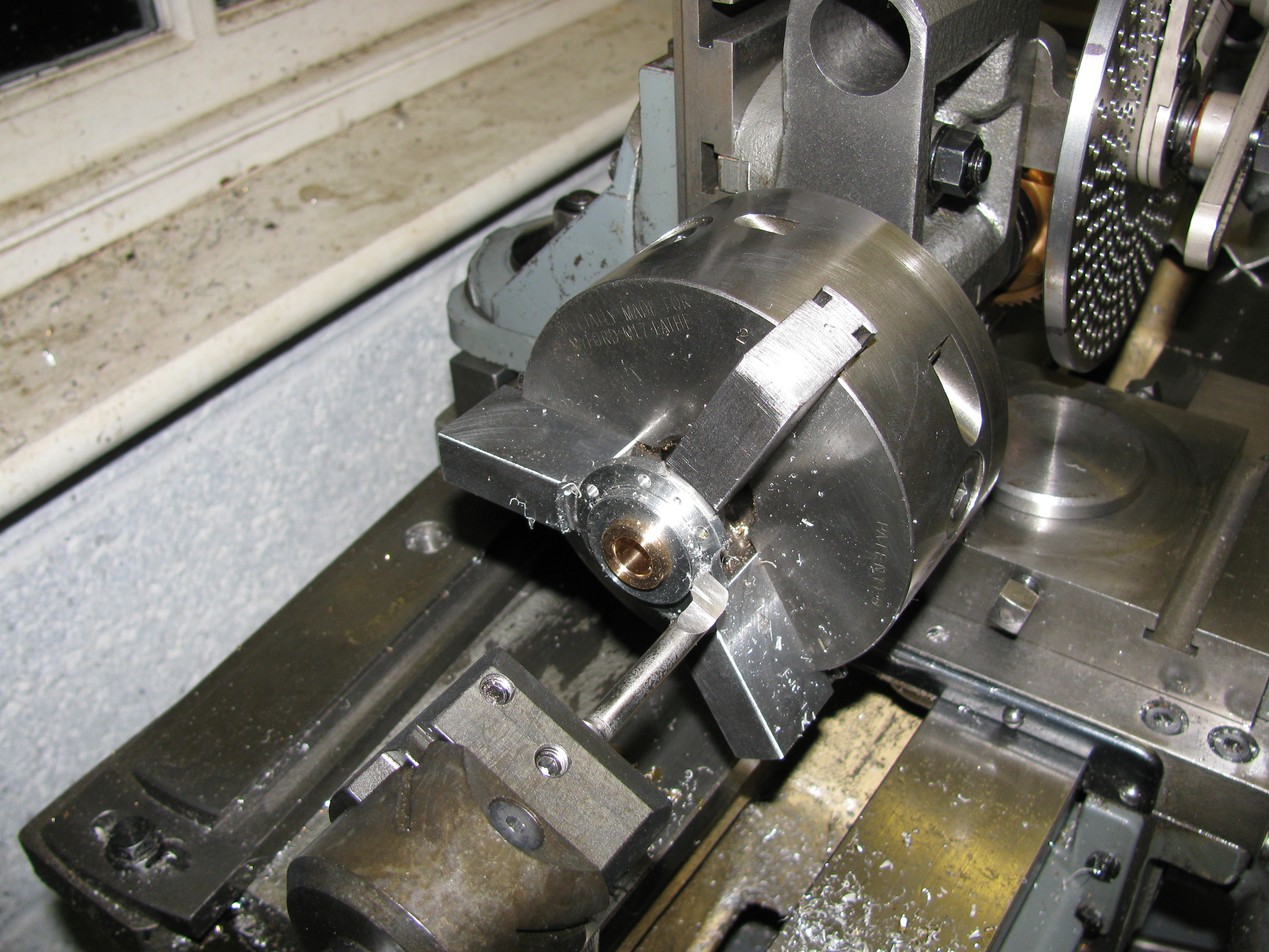
2010-10-23 - Facing to length
I tapped the two 8BA forcing screw holes, and then, using the soft jaws and paper protection again, took a shave off the outer end of the bearing bush to the exact 7⁄8″ length. The photo shows the tailstock centre being used to make sure the job is sitting properly in the chuck. The next job was to drill and tap the crankcase. (1 hr)
2010-11-06 - Oil hole

The lathe was set-up for drilling the oil-hole in the Timing-end bearing housing, and the same set-up was used, at a different angle, to put the hole in this one as well. The last job is to lap the bore. (½ hr)
.