
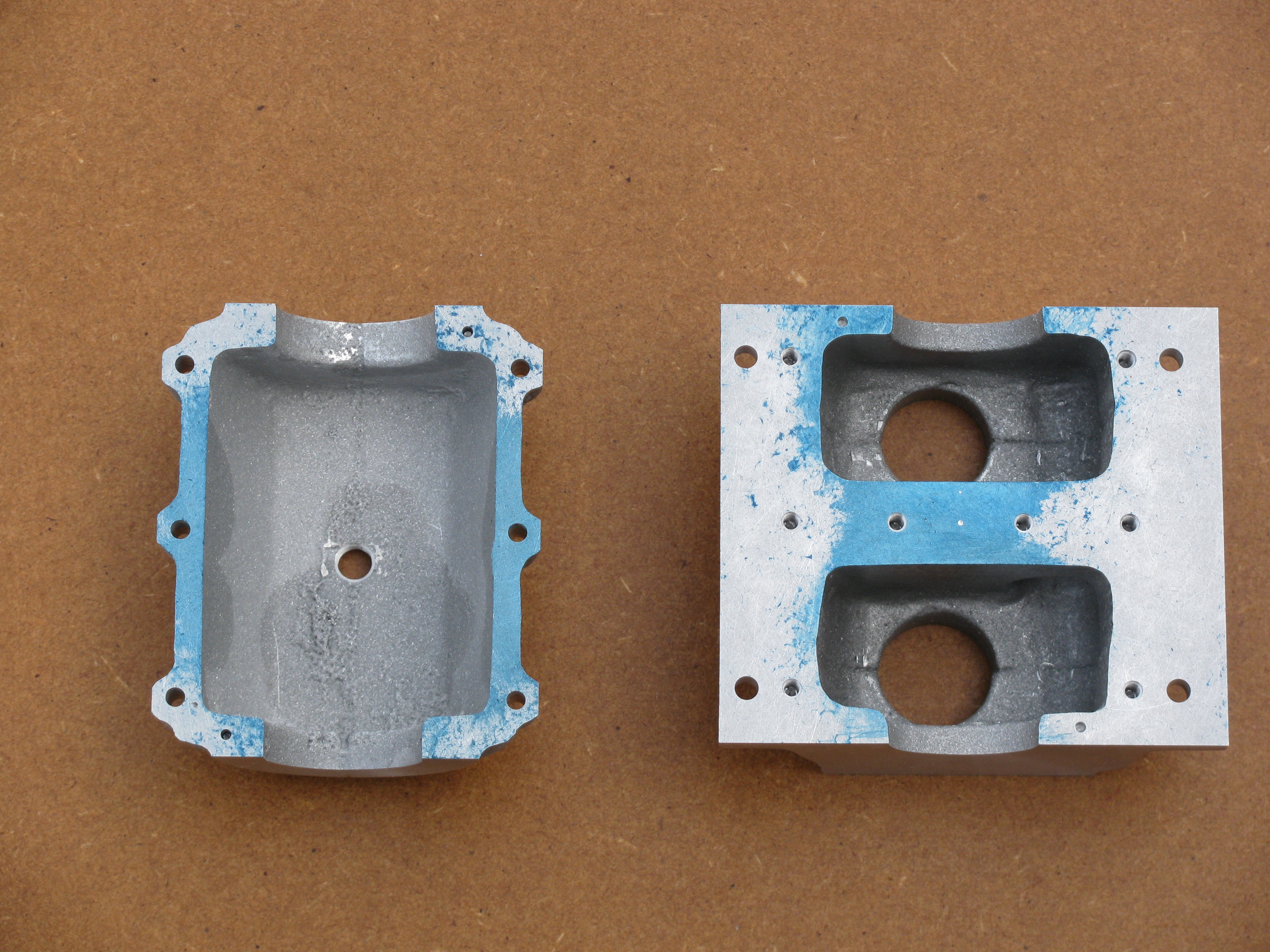
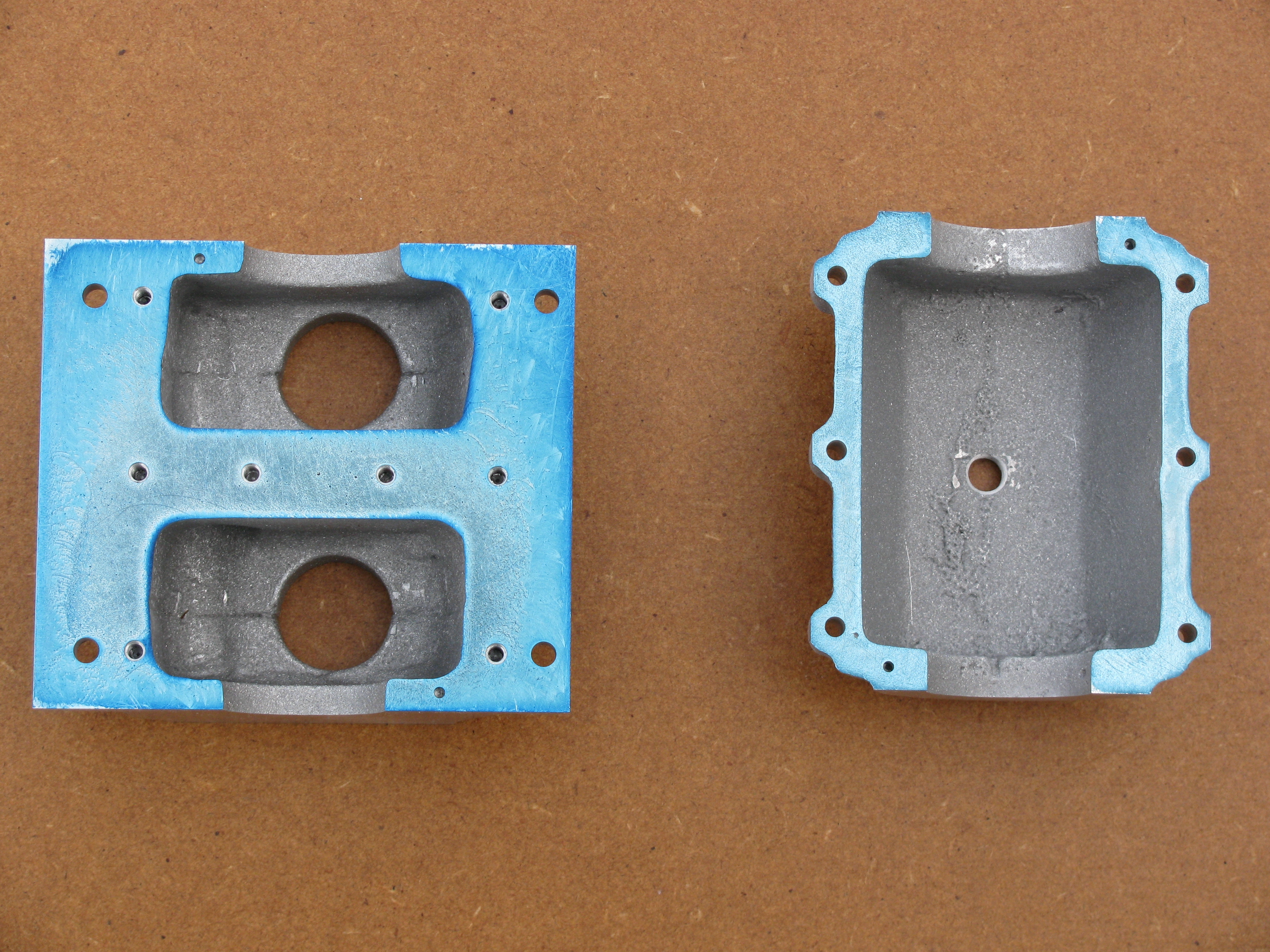
Crankcase
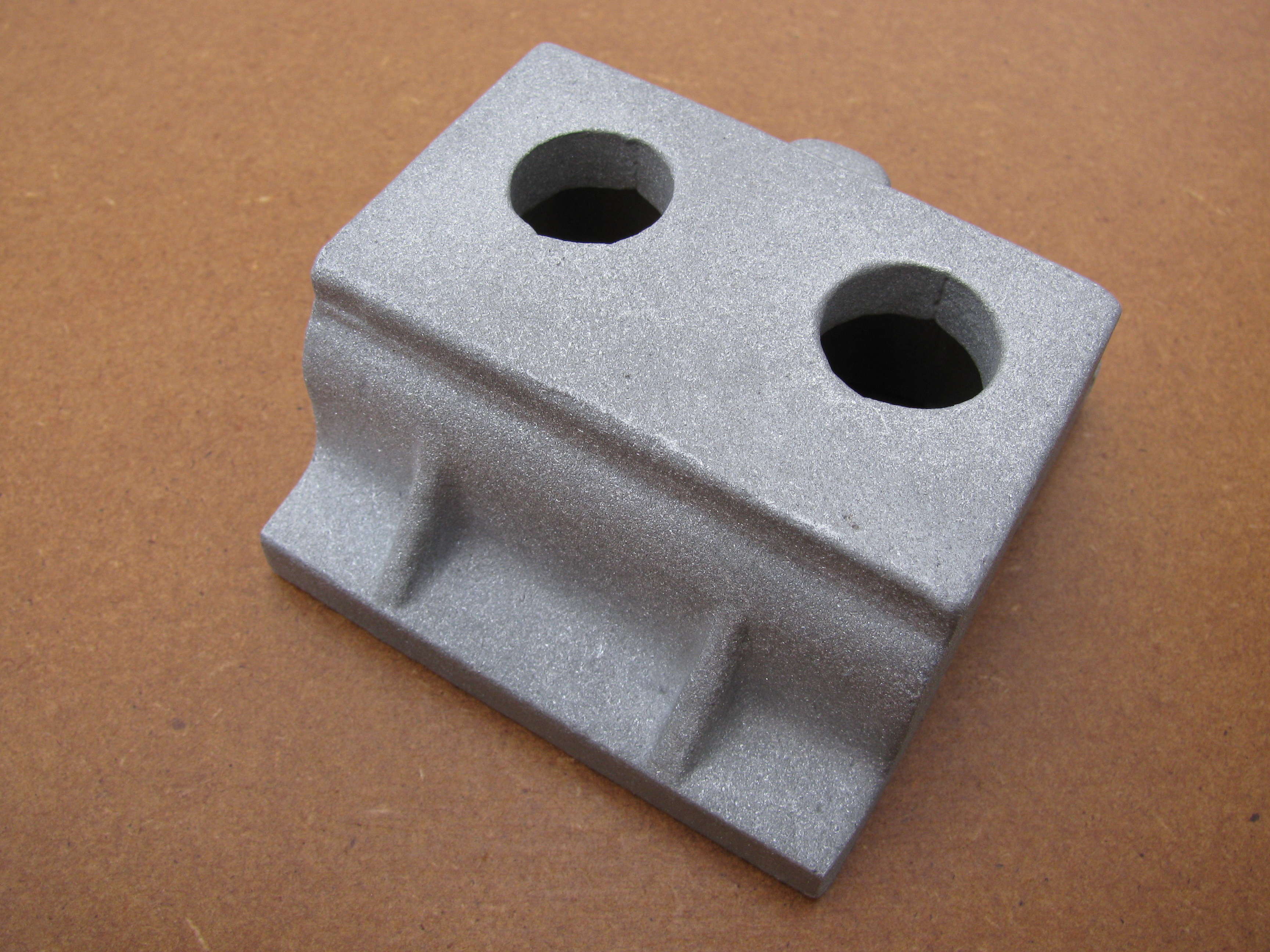
The lateral centreline needs to be determined before the end faces are finish machined (with the sump), so that the tapped holes for the centre bearing cap and sump can be located prior to final machining. Initial measuring up of the casting shows a considerable discrepancy in the lateral positions of several features. It is clear that if the mounting flange is left at the design width of 3″, it cannot be reconciled with other more important dimensions. It may need to be reduced by something like an 1⁄8″ on the camshaft side to maintain symmetry while allowing an adequate amount of metal round the tappet holes. Detailed measurements of the casting will be needed as work progresses before the best datum positions can be decided upon.
Externally, it does not look as if it will be possible to get the gussets equally positioned. The position of the breather boss is probably the most important feature to aim to centre. The cored holes for the cylinders seem to be offset a little and these will need to be checked carefully for sufficient metal to clean up. The crank race core holes also need to be taken into account, as there is not much latitude on the central web. Both end faces need to be cleaned up to enable a definitive longitudinal position to be arrived at.
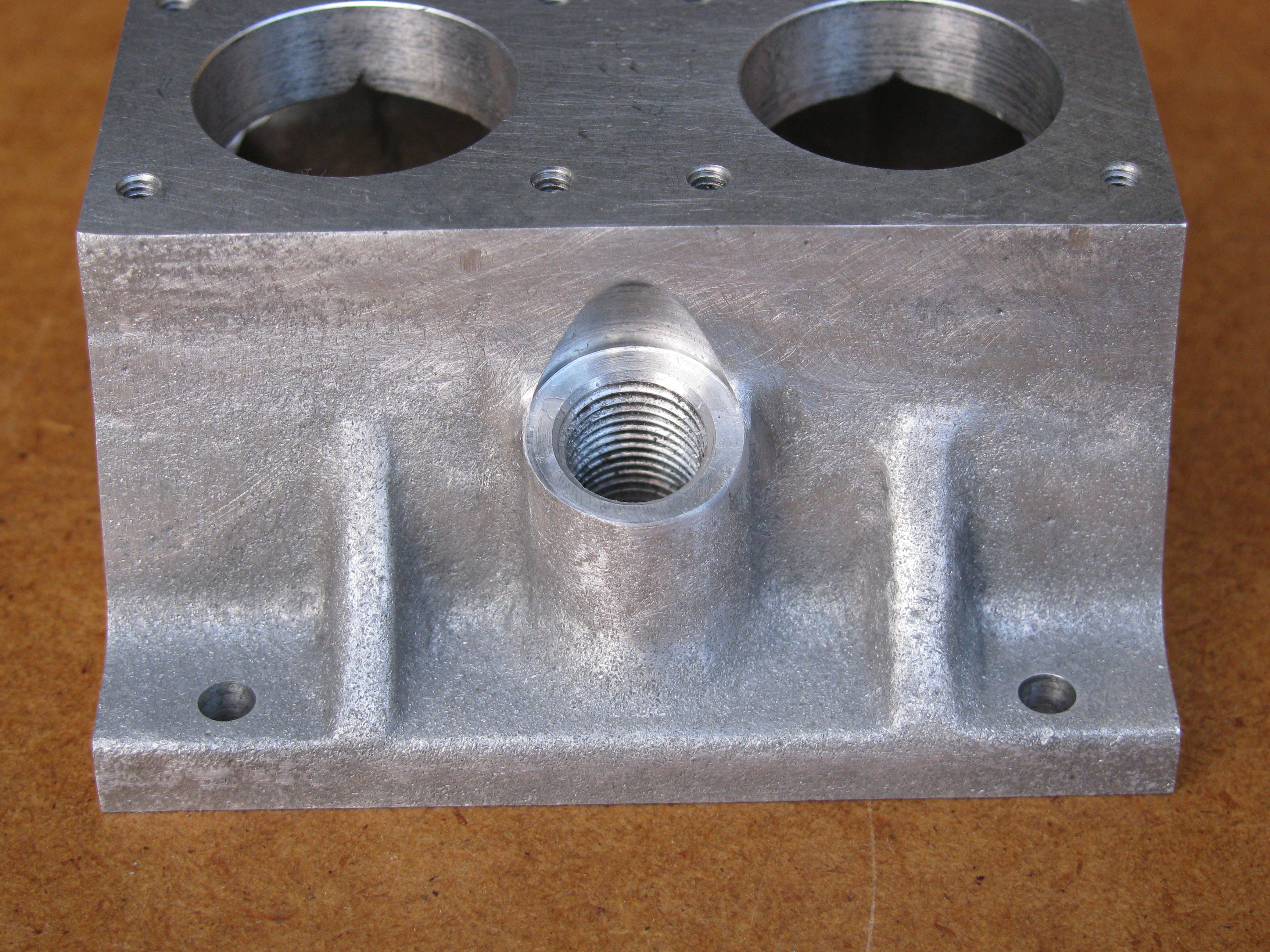
The breather boss is not to drawing. It has been altered to allow it to be cast without a core or loose piece, which would be OK, except that the top of the boss is rounded off and reduces the seating width. It is not wide enough to get the breather in without cutting into the side of the casting. This is consistent across all the castings in stock at Hemingway when I called. Several solutions have been explored, and the asymmetry of the casting has caused confusion. Initially it seemed it would be necessary to cut into the top face of the casting and set it considerably closer to the centreline than as drawn. Another attempt showed that by lowering the height of the facing, the cutaway could be well clear of the top. This will involve a redesigned filler to clear the side of the casting. The angle has also been increased, from 15° to 17° to ensure that the hole in the casting does not interfere with the central sump bolt. To machine it, drilling undersize from the bottom will establish the correct lateral position, then, working from the top, the longitudinal position can be verified from the boss. The face can be machined with a ½″ slot drill, followed by a boring head to create the clearance in the cut away, and counter-boring and tapping.
The edge above the breather boss should be used as the initial reference for setting up square. The cylinder flanges come quite close to this edge, so an uneven width of the margin would be quite noticeable.
I see no particular reason why the end holes for the bearing housings need to be 11⁄8″ diameter. There is no need to be able to get the crankshaft through, so they could be smaller. The bearing housing bolt holes appear to come extremely close to the bore at the timing end, and at the flywheel end it would be helpful to reduce the pitch circle so that the nuts do not overlap the edge of the bearing housing, for which the piece of bar supplied is to finished size. Reducing these bores to 11⁄16″ would do what is needed. It will also allow a little more lattitude in positioning the crankshaft centreline. The angular position of the ring of holes at the flywheel end could usefully be altered to equalise the disposition about the cut-out in the flange needed to clear the camshaft bearing.
Particularly with the narrower mounting flanges, the 3⁄16″ Holes for 2BA engine mounting bolts seem infeasibly large, and a 2BA nut looks out of scale. A spot-face for a 4BA looks as though it would be more in keeping, and as probably the smallest of several possible sizes, this is what I will initially drill for. Moving the holes in from the ends by 1⁄16″ to 5⁄16″ also looks better balanced to me. Finding a best compromise position across the width of the flange is also difficult. Too far out and the edge of the flange looks weakened, while too far in puts the hole too close to the outside profile of the sump.
2010-03-14 - Making a start
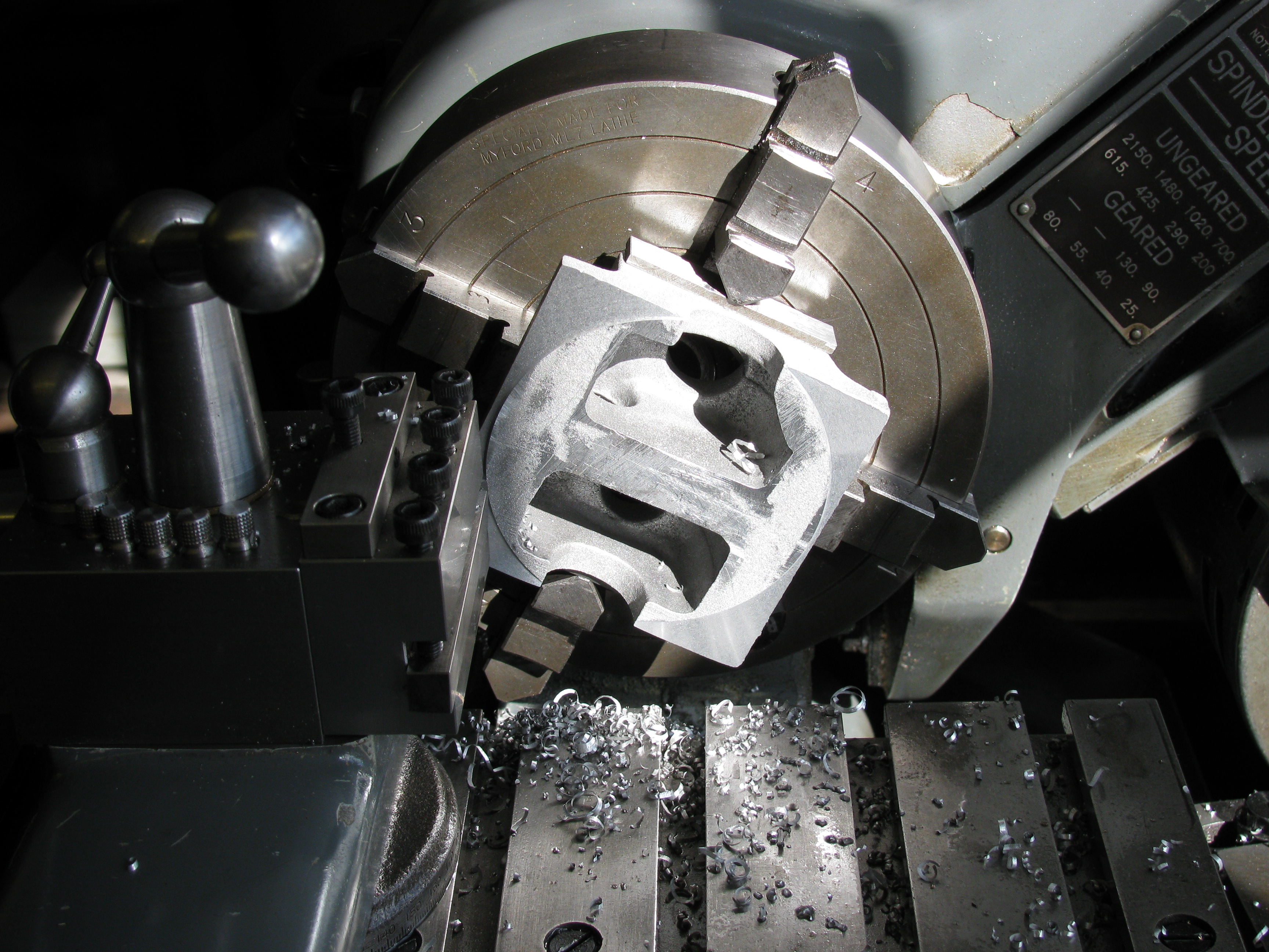
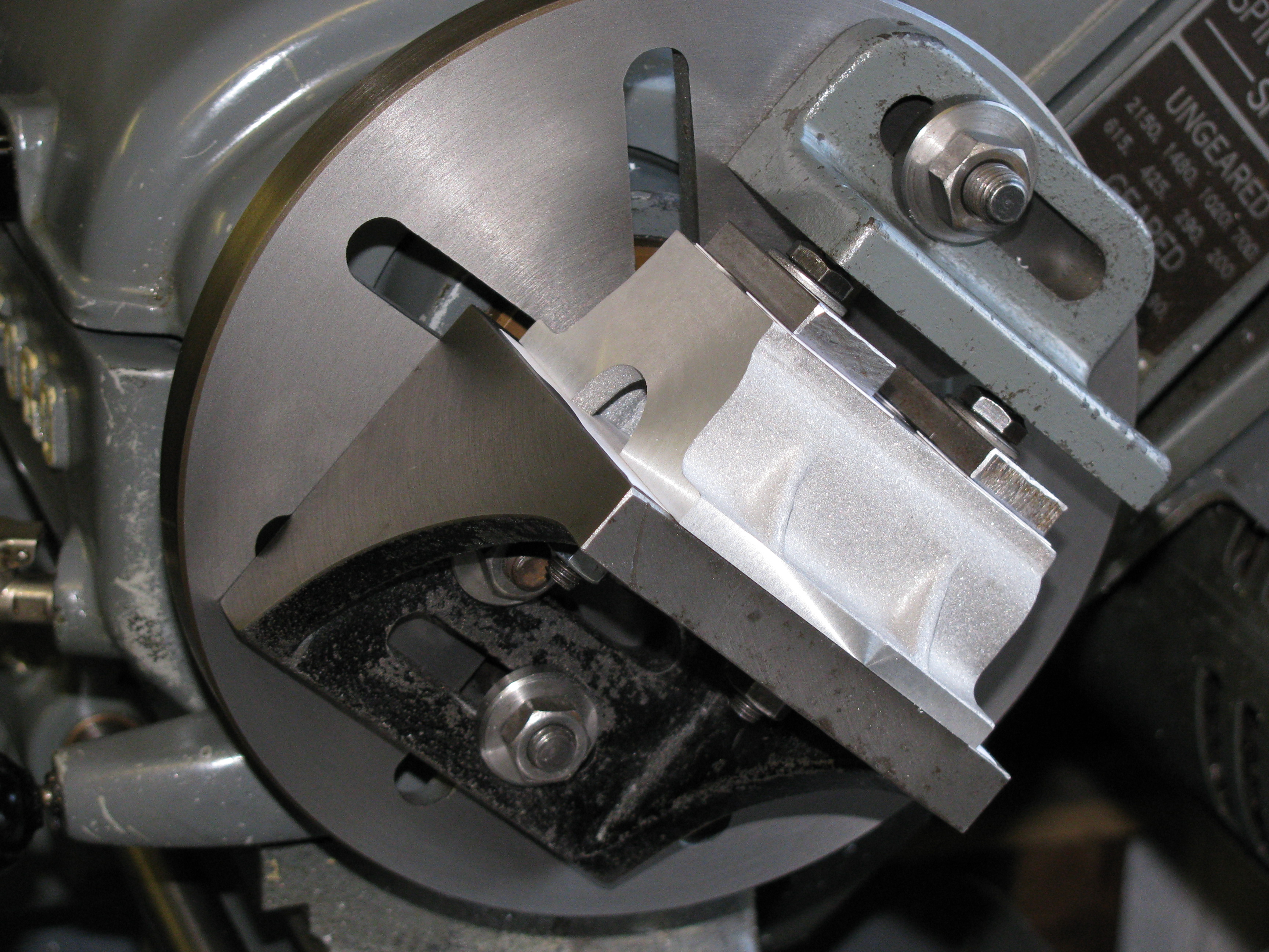
After fiddling about with filing and rubbing on a diamond lapping plate I decided the best way to get an accurate measurement of the thickness of the engine mounting flanges would be to take a trial cut. Set it up in the 4-jaw and took 35 thou off to clean up all over. Measuring up showed that, naturally, the worst discrepancy in thickness was across the diagonals and therefore impossible to correct. There was also some difference from side to side. I set it up on the faceplate with 10 thou shim under the camshaft side, and took a light cut of about 15 thou to clean up the surface all over.
For machining the remaining cuts the casting needs to be held flat. This is best assured by using a faceplate, but there is no way to hold the casting centrally by the top face. The two cored cylinder holes are much too close together to allow bolts through the faceplate slots. A long term solution I have in mind is a small faceplate consisting of a chuck backplate with a false face mounted on it having tapped holes all over. That is more work than I wanted, so I opted to make a mounting plate to go on the faceplate. I chose a 4″ square of 3⁄8″ plate, tapped a couple of 5⁄16″ holes in it and faced both sides, on the faceplate. (6 hours)
2010-03-20 - Faceplate investigation
As the lathe turns a face slightly concave, as it should, I decided to scrape the outer face of the sub-plate flat. After I had done this I checked the thickness at the corners and found them off by a thou or so. Mounting the plate on the faceplate gave a similar runout. I tried carefully cleaning the spindle nose and faceplate mounting, and it was still off. So I put a clock on the faceplate and found a runout of 0.0012″. I did not want to re-face the plate, so I re-machined the sub-plate and marked both so that it could be mounted in the same orientation each time. After tapping two suitably positioned M5 holes in the sub-plate, the crankcase was clamped on by the cylinder core holes and 30 thou taken off the bottom. There remains 46½ thou to take off.
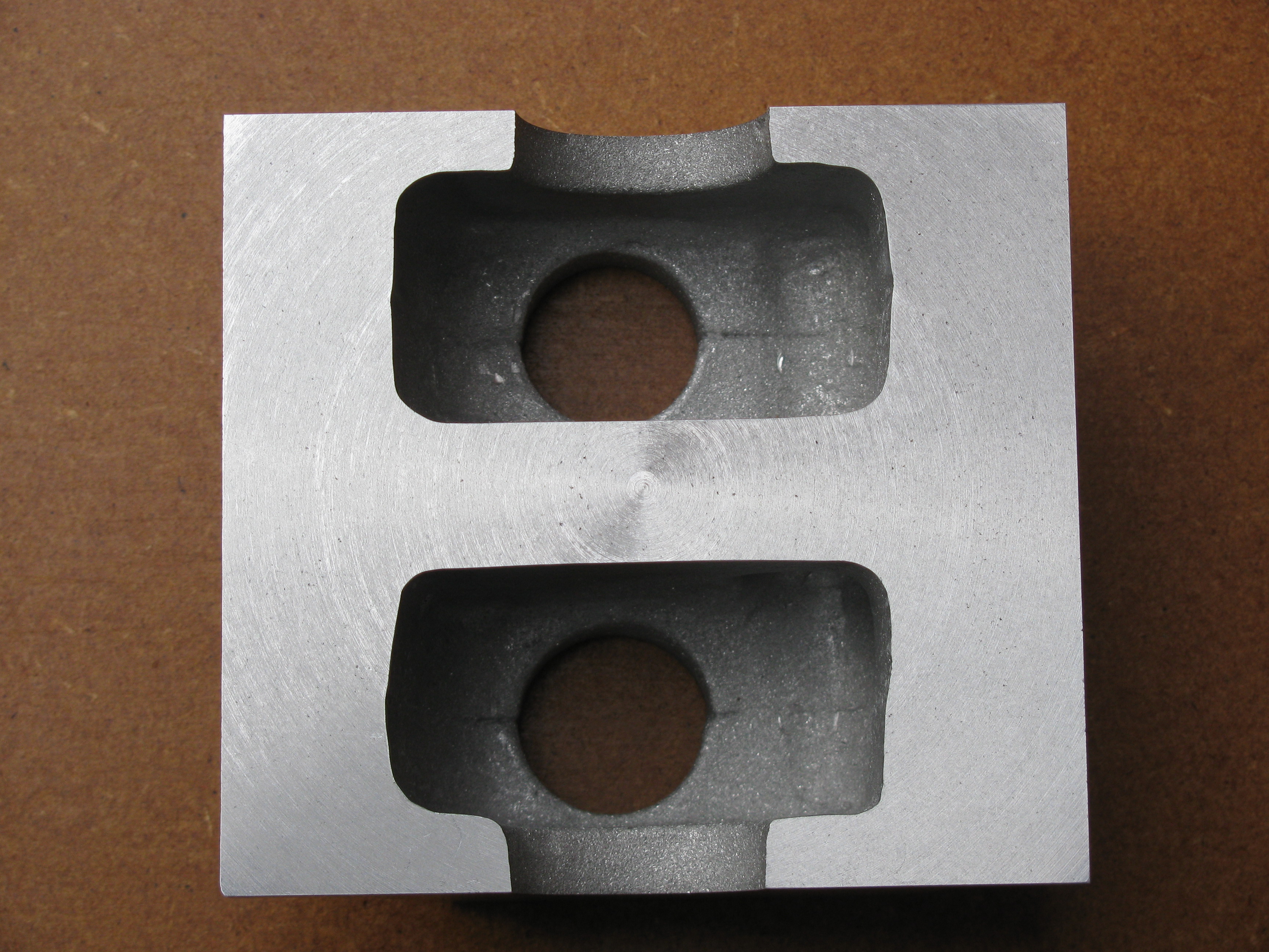
Using a depth micrometer to survey the thickness of the top of the crankcase, I found that it was already only a few thou over ¼″ at the thinnest point, between the No1 tappets, where it should be 9⁄32″. The cores have a bulge which appears to be intended to create a clearance in the camshaft tunnel. As this is bored 9⁄16″ for a ½″ camshaft this is not really necessary. Leaving enough metal to need boring right through would make machining a little bit more difficult as there would be a long intermittent cut, but would have left more support for the tappets just where the side thrust is highest. It may be worth fitting guide bushes as Westbury suggests. The top surface of the casting has not been machined back far enough to remove the cast corner radii, so it still needs a bit more off. The engine mounting flanges will end up well over 3⁄16″ thick, whatever I do. I decide to take 1⁄32″ off the bottom and 1⁄64″ off the top. (2 hours)
2010-03-21 - Not thinking

 Set up on the sub-plate, bottom out and take cuts of 26 and 4 thou. The result is as close to parallel as I can measure,
with 0.0165″ to come off, exactly as intended. Decide to aim to leave 1½ thou for lapping. Set up other way out, dogging direct
to the faceplate with a protective piece of paper under. I knew there was a bit of runout at the rim of this plate, but it did not seem to
be bad near the middle. Now, when touching the tool on the job for a start reading, I should have realised
there was something amiss when it did not touch both sides. It was late, and I
wanted to finish. I took the
planned 15 thou off in 2 cuts. Measuring up, it was +.0002″ at the timing end and +.0010″ at the other. This much will lap out later, but it will probably
end up a tad under size. In the meantime I need to remember to use the bottom as the datum face, which it will be until the sump is fitted for
boring. Also, maybe the 7″ faceplate needs sorting out. I do vaguely remember years ago deciding that the 9″ plate was better for accurate
work. (1½ hours)
Set up on the sub-plate, bottom out and take cuts of 26 and 4 thou. The result is as close to parallel as I can measure,
with 0.0165″ to come off, exactly as intended. Decide to aim to leave 1½ thou for lapping. Set up other way out, dogging direct
to the faceplate with a protective piece of paper under. I knew there was a bit of runout at the rim of this plate, but it did not seem to
be bad near the middle. Now, when touching the tool on the job for a start reading, I should have realised
there was something amiss when it did not touch both sides. It was late, and I
wanted to finish. I took the
planned 15 thou off in 2 cuts. Measuring up, it was +.0002″ at the timing end and +.0010″ at the other. This much will lap out later, but it will probably
end up a tad under size. In the meantime I need to remember to use the bottom as the datum face, which it will be until the sump is fitted for
boring. Also, maybe the 7″ faceplate needs sorting out. I do vaguely remember years ago deciding that the 9″ plate was better for accurate
work. (1½ hours)
2010-03-22 - End faces & datum edge
I decided to tackle the faceplate. I took it off and carefully cleaned the spindle nose and bore and threads of the plate and re-mounted it. I then took a very light cut, about 2 thou across the face with a carbide tip, starting at 80 rpm and increasing in steps to 200 near the centre. An immediate check showed that there was now a surprising ½ thou runout at the rim. I decided to tighten the spindle bearings a little - it is not so long since I had it apart. Another cut resulted in minimal runout. Removing and refitting the plate gave a runout of ½ thou again. Trying again with careful cleaning and tightening it well reduced the runout to around a tenth. Evidently this plate is very sensitive to how it is mounted. The sub-plate will need machining again now.
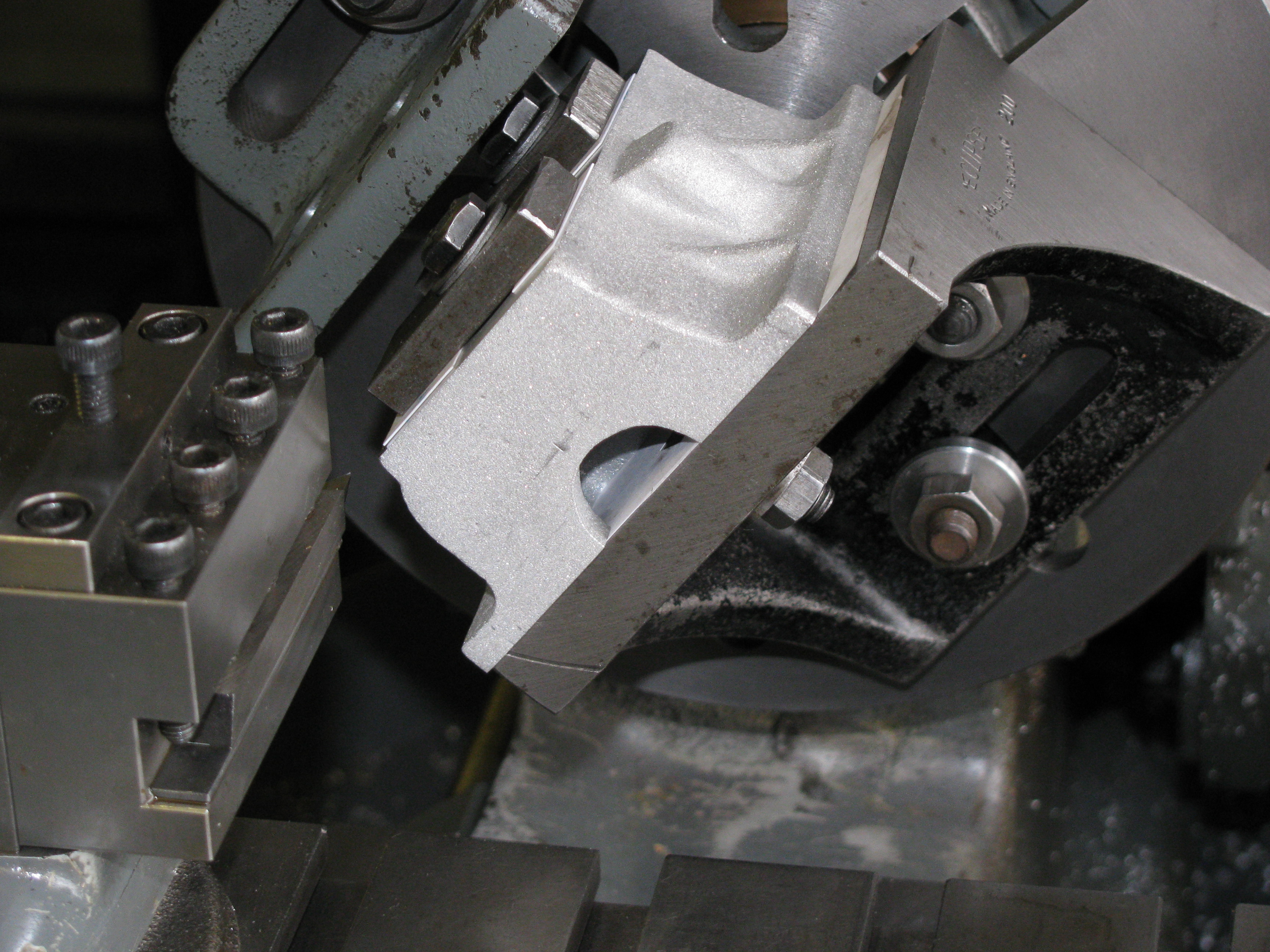
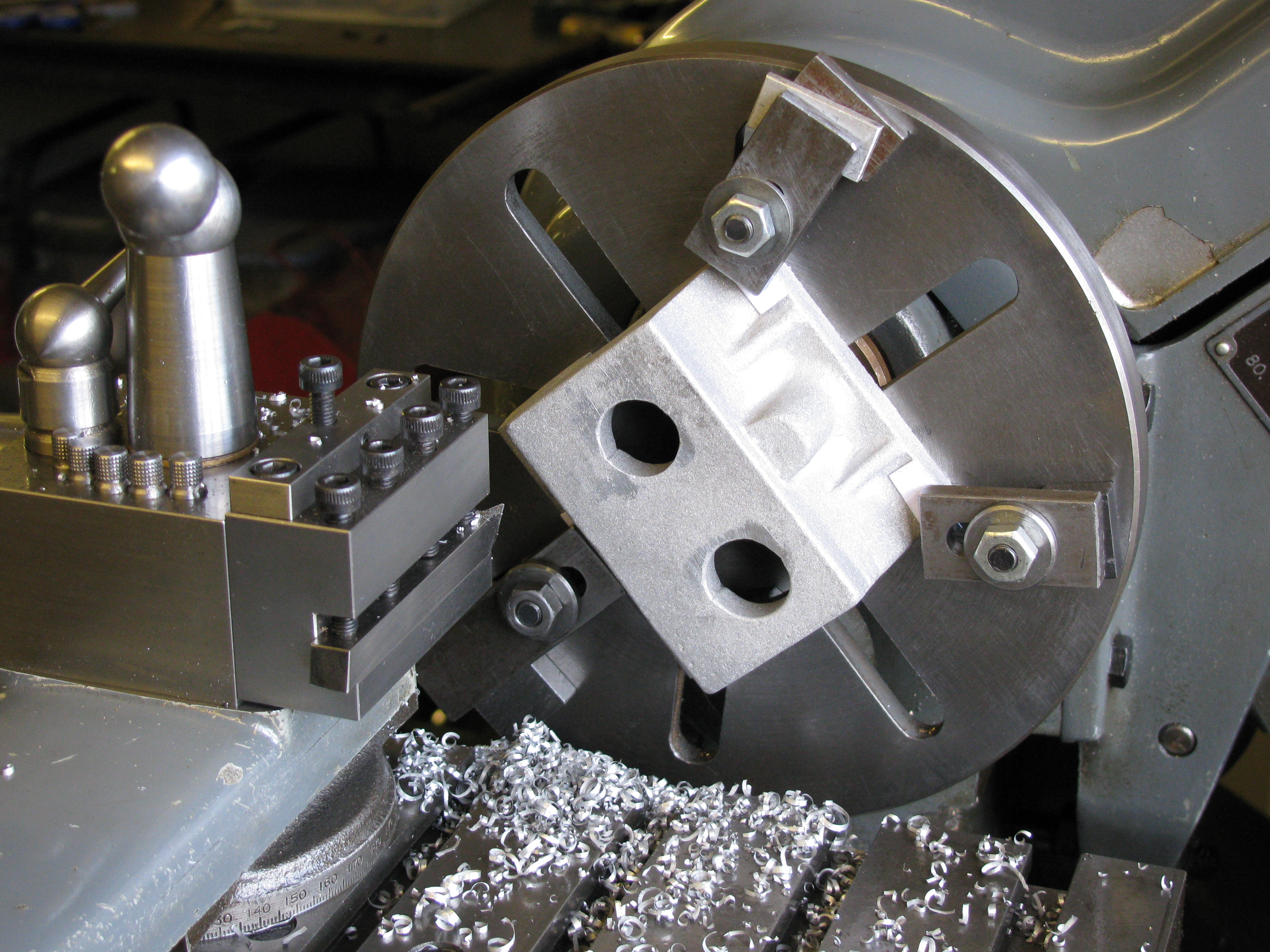
I set the crankcase up on an angle-plate for roughing out the ends. The top edge on the breather side was set square to the faceplate and a 40 thou cut taken on flywheel end. This was enough to all-but clean up along the top edge where the casting draw is greatest. Turning it round and using a parallel between the machined end and the faceplate, two cuts of 40 thou were needed to clean up the timing end face.
To get a datum for measuring up, I set it up camshaft side out, again using the top edge on the breather side as reference. A check on the camshaft side showed that this was running pretty true as well, and the machined ends were pretty good too. A cut of 20 thou maximum was taken to clean up the edge of the flange.
Careful measuring up and drawing out showed that the crank-race cores were a little over 1⁄32″ too far apart. It should just be possible to get the cored holes for the cylinders to clean up. There are places where the casting will not finish to drawing. The end walls may be a bit under thickness. There is a tricky compromise to be achieved between the two features, and it will probably result in the timing end wall being a bit thinner than at the crankcase end. Laterally, there is some mismatch between the two sides of one of the cores, resulting in about 40 to 50 thou discrepancy. The sump sealing area will be slightly compromised, but not enough to worry about. Working out how best to deal with recalcitrant castings is a job where CAD is very helpful. You can make different drawing layers for what you want and what you have got, and move one around in relation to the other to get the best compromise. (4¼ hours)
2010-03-28 - End faces, again
To get to finishing size, I took just under 40 thou from the timing end and 60 from the flywheel end, leaving 10 thou to come off each, when set up for boring with the sump. (1 hour)
2010-04-11 - Drilling and tapping
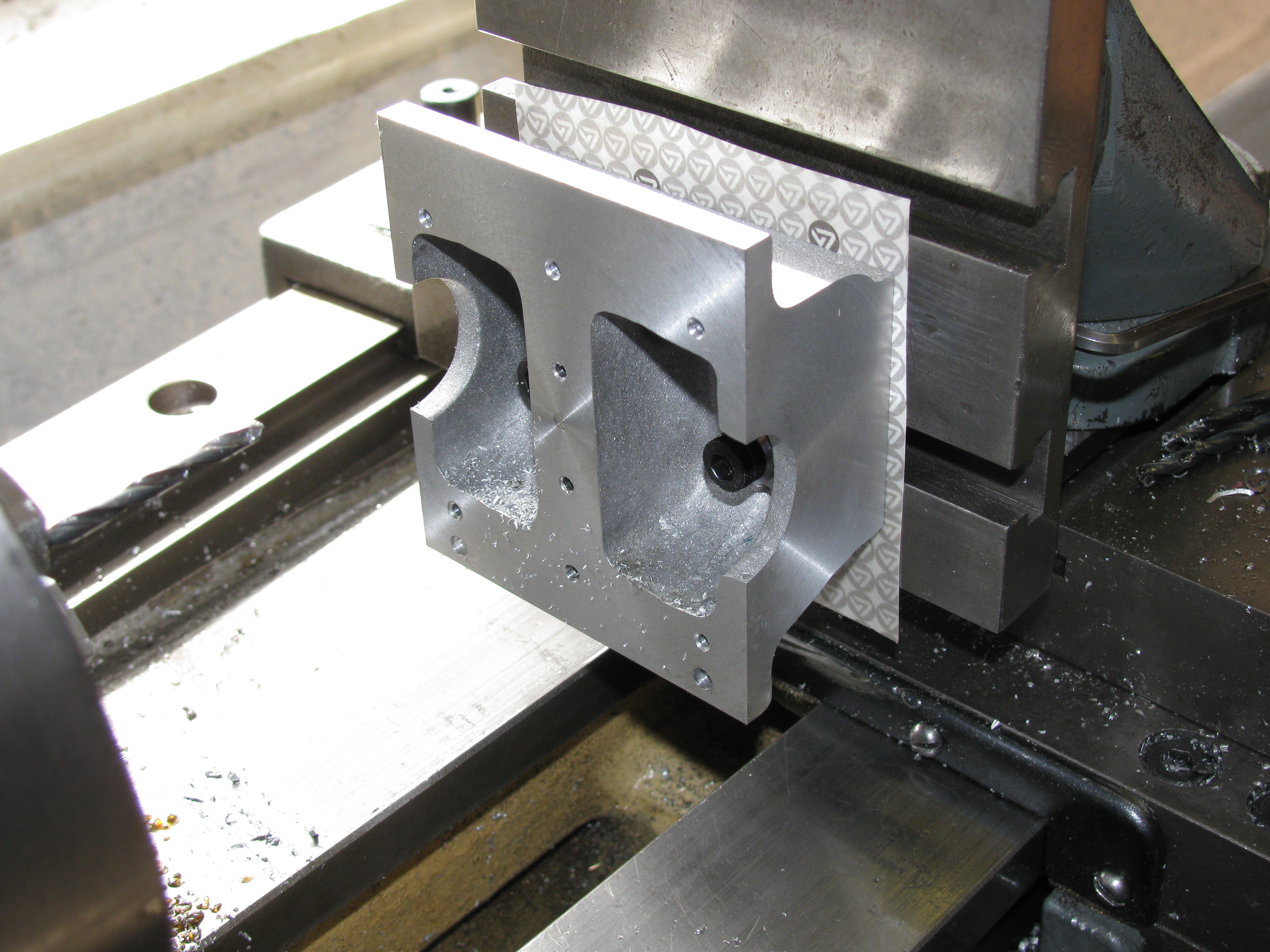
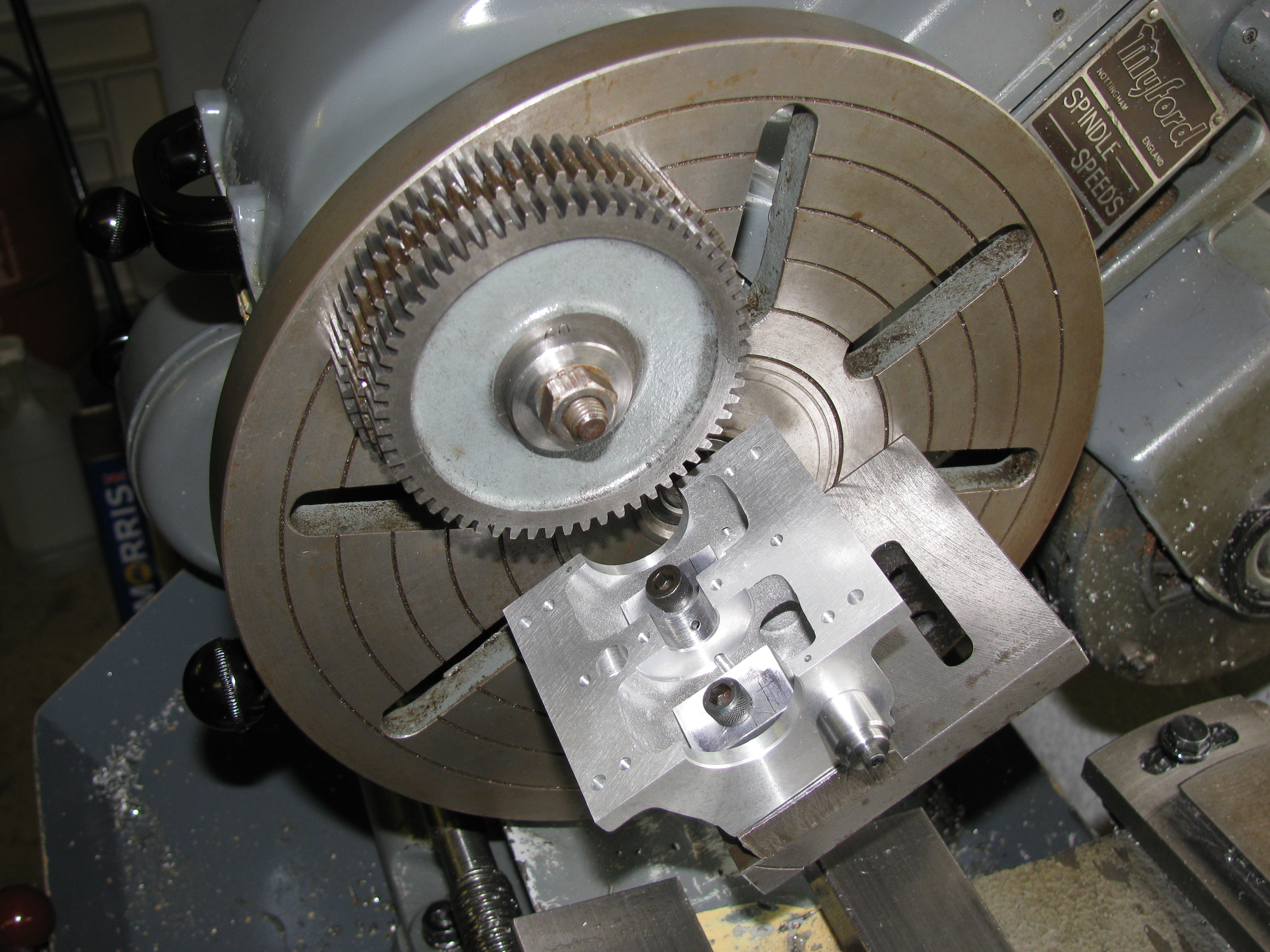
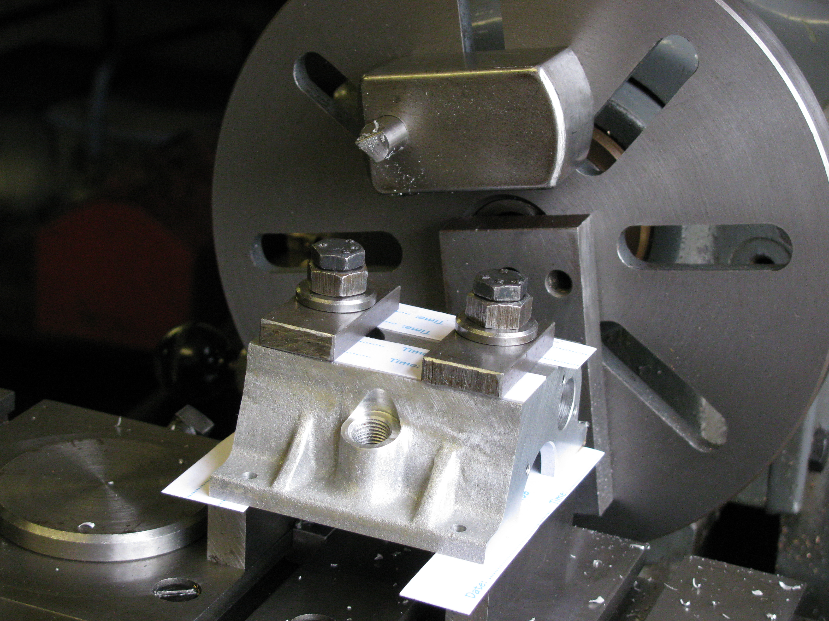
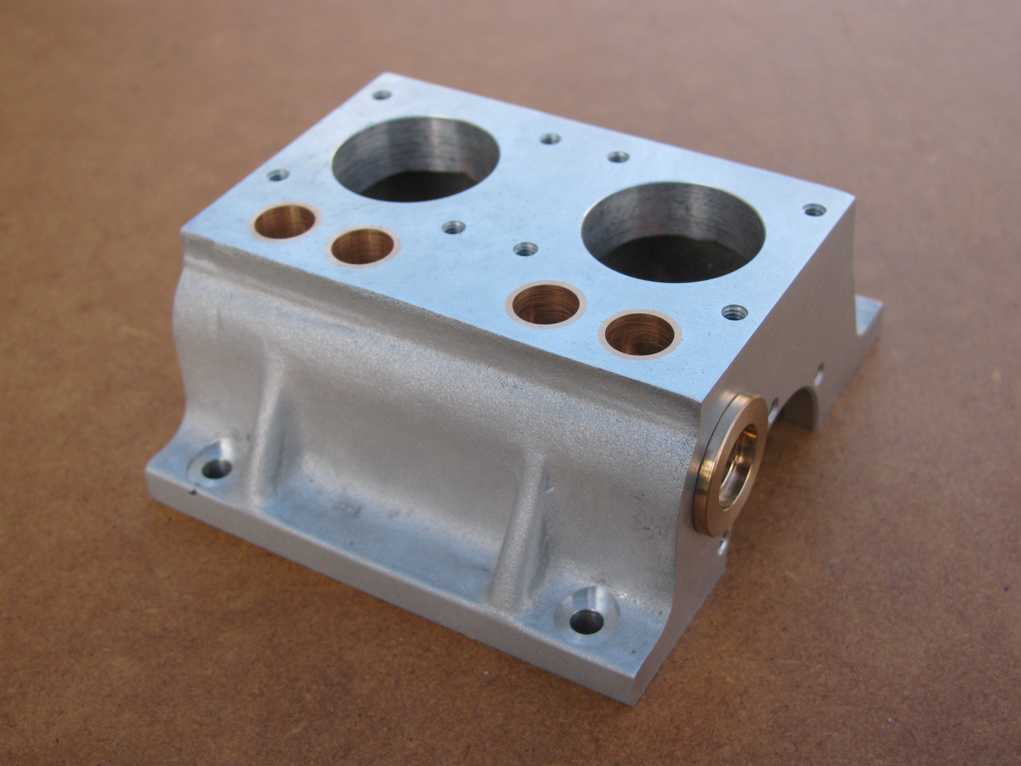
After making some tee-nuts with M5 tapped holes for use with little clamping dogs, I set the crankcase up on the vertical slide for co-ordinate drilling holes in the underside for centre bearing cap, sump bolts and dowels, and engine mounting bolts. Rather than tapping these holes in the lathe, I used my tapping and staking tool. Having a fine tube on an air blow gun certainly makes it much easier to clean the swarf out of the bottoms of blind tapped holes. We now have an assembly! The holes line up well enough to get all the bolts in without difficulty, but with no play.
2010-04-11 - Lapping
The joint faces were machined slightly concave, as is normal. Using a borrowed cast iron lapping plate I ended up with both crankcase and sump high in the middle. I tried the sump on my diamond lapping plate, which improved it quite a bit but still left it hollow along the longitudinal centre line. Using a piece of 400-grit wet or dry paper held on the large surface plate by a film of paraffin it lapped up nicely. Although I am not keen on this method, as I think the paper tends to ride up a little and round off the edges, I felt confident enough to try the crankcase. The result was certainly good enough, but there was indeed a little bit of rounding off, perhaps as the sheet was a bit worn. Trying a fresh sheet seemed to improve it. Because of the false start the overall height is -1½ to -2½ thou. It should be possible to lap this slight taper out when dealing with the top surface. It takes a while to clean all the lapping gunge out of the tapped holes, but this needs to be done meticulously. Having air in the shop makes it much easier, using a fine jet blow gun. (2½ hours)
2010-07-31 - Fitting, and making a jig
Having decided to use the dowels to locate the sump, even though it is slightly out of position, 3 of the sump retaining bolts would not fit properly. Today I eased these holes using a needle file and a riffler until the cap-heads go in nicely. The sump is not marked for orientation, and could still be put on either was round. I need to remember that the small external blow-hole in the casting goes at the flywheel end.
Now the crankcase and sump are properly fitted, they can be bored for the crankshaft. I decide to locate the crankcase for the first boring operation using a toolmaker's button. The problem with that is there is a half-round hole in the casting just where the button needs fixing. I dealt with this by making a couple of little plates to clamp together over the gap to take the button. Trying these in place I threw up a slight burr on the inside of the crankcase. It will need to be removed before I go any further. (3 hours)
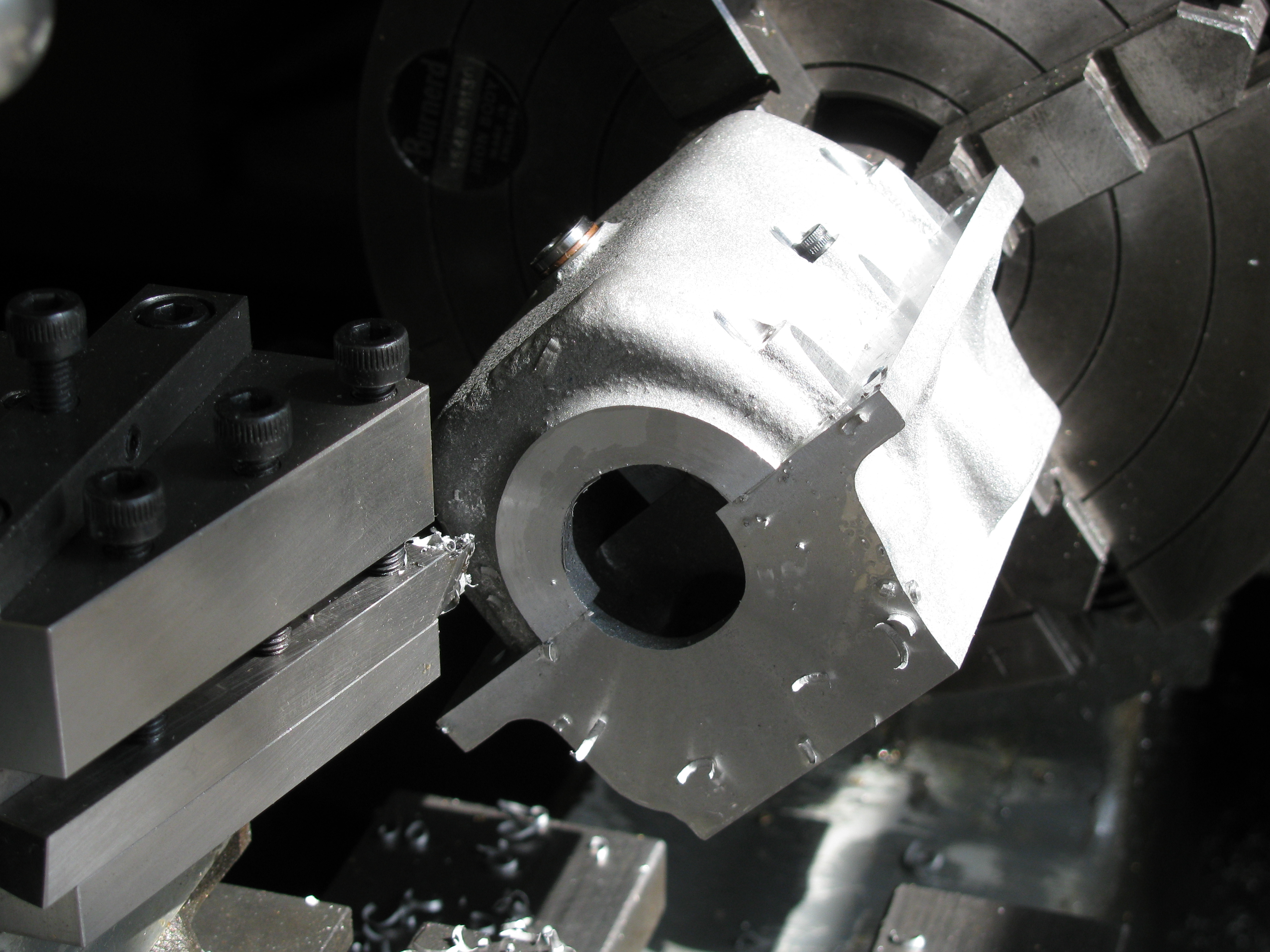
2010-08-01 - Boring flywheel end

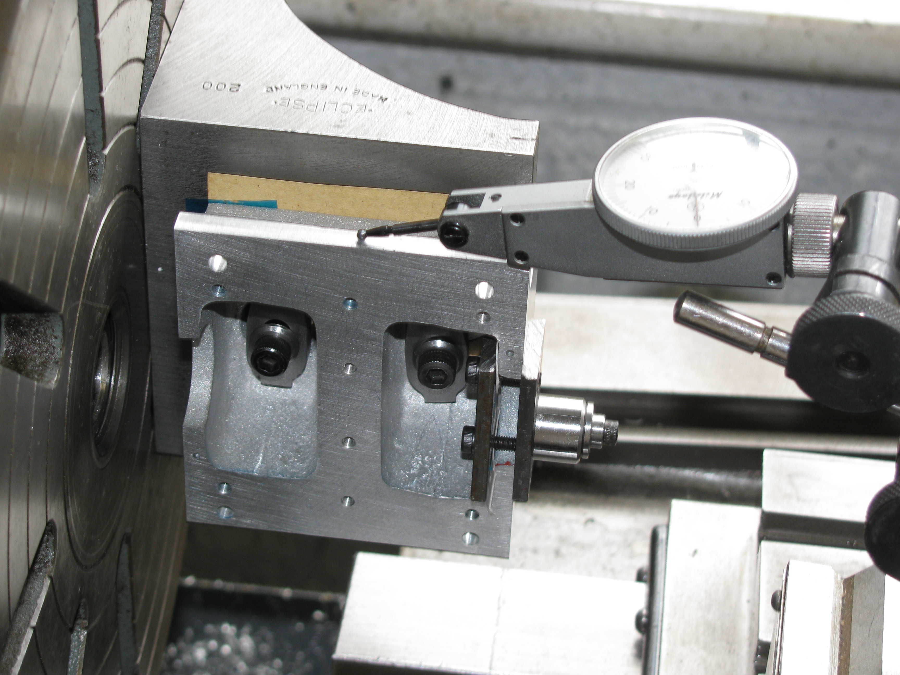
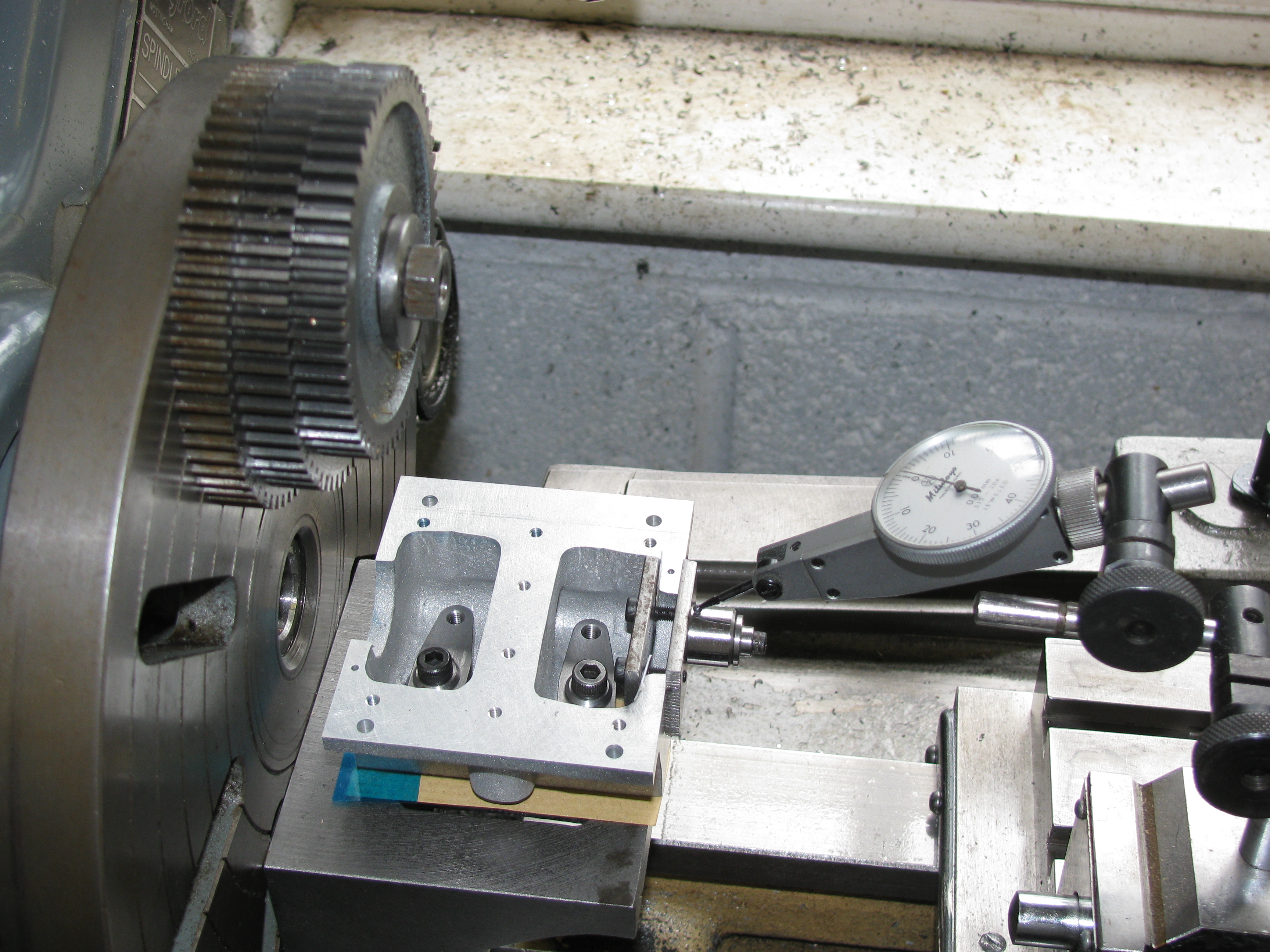
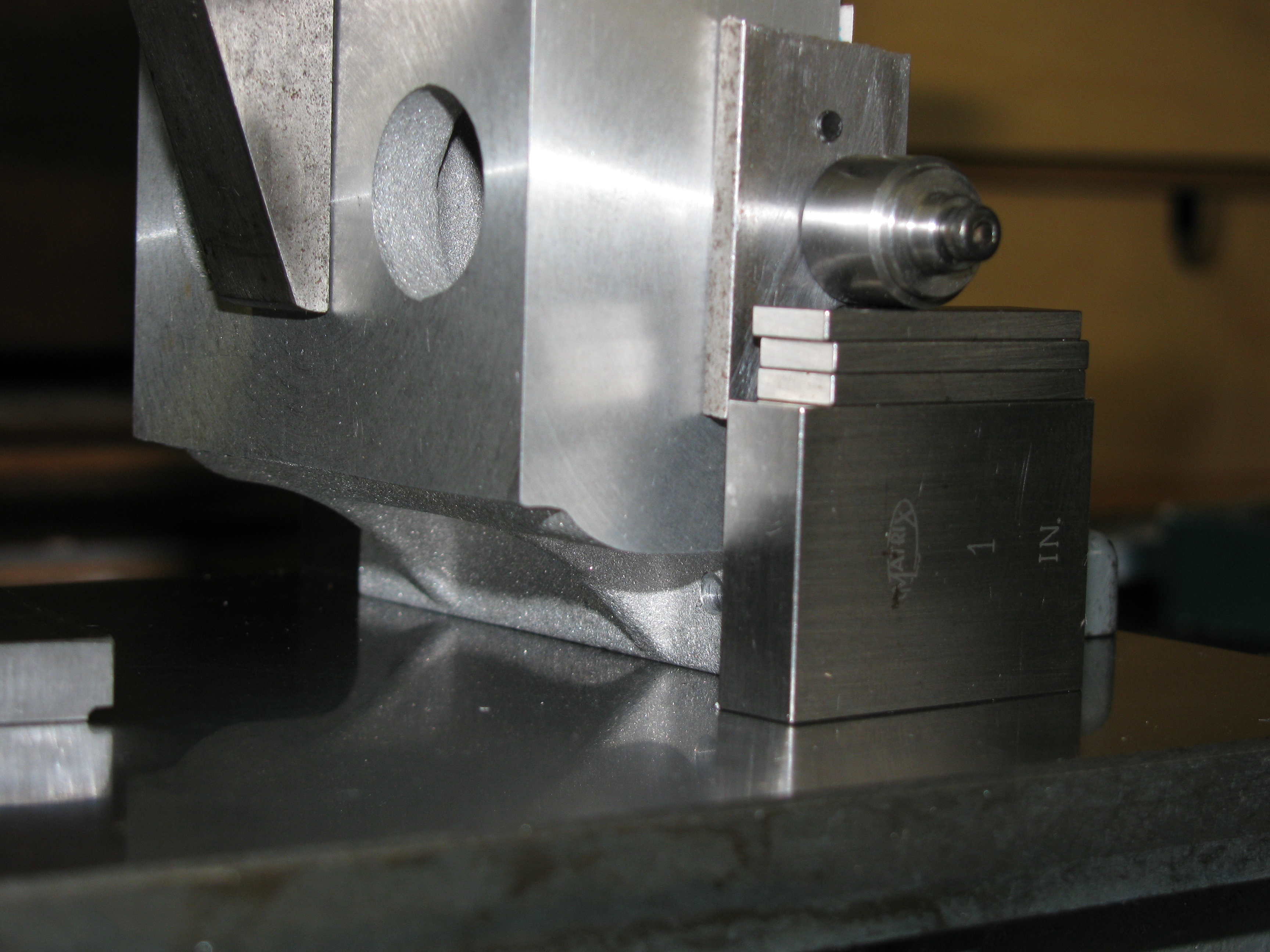
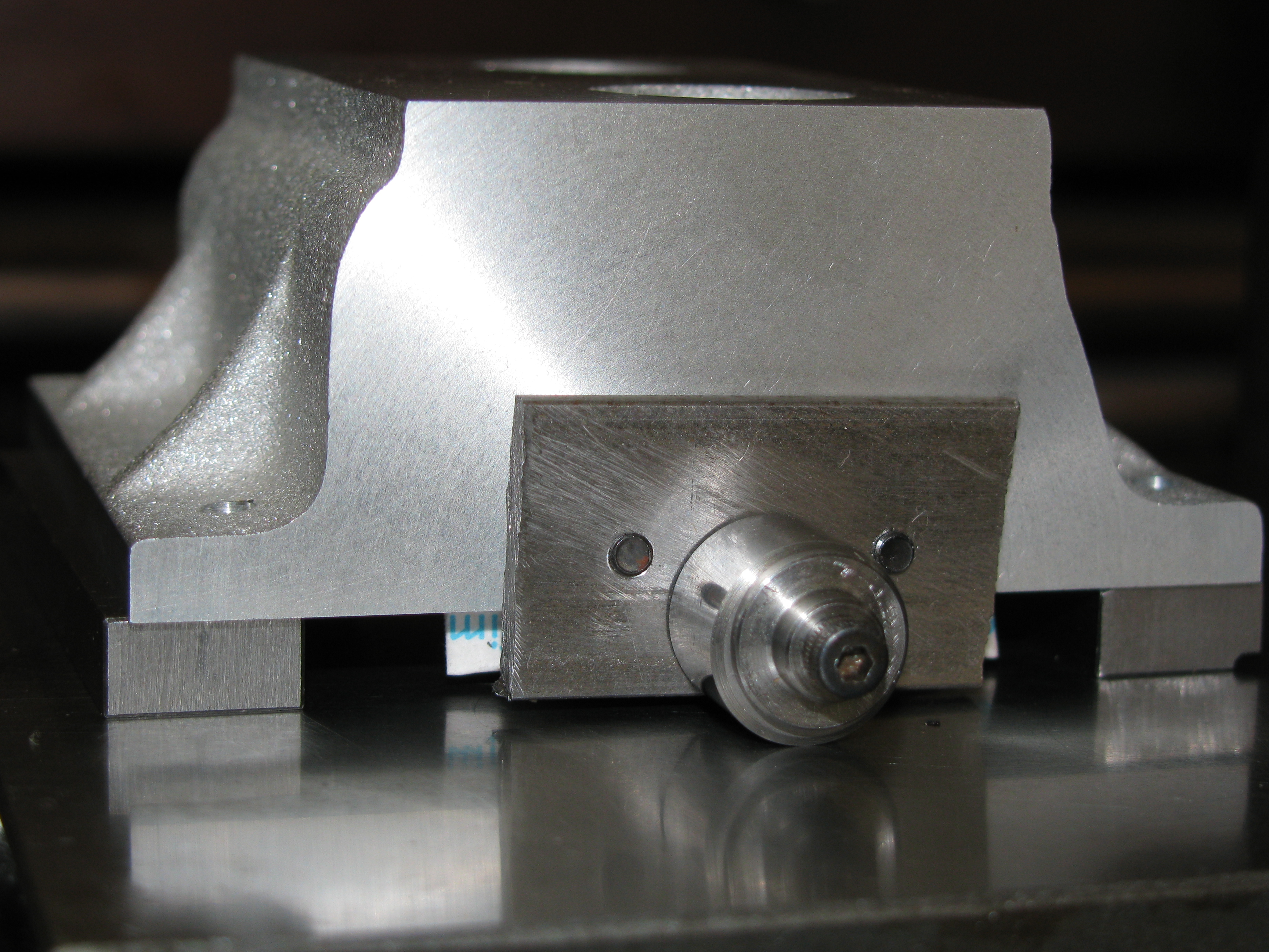
Having removed the burr I re-fitted the plates and button, which was then positioned using gauge blocks from the datum edge, and home-made, but fairly accurate, ¼″ parallel packers under the mounting flanges.
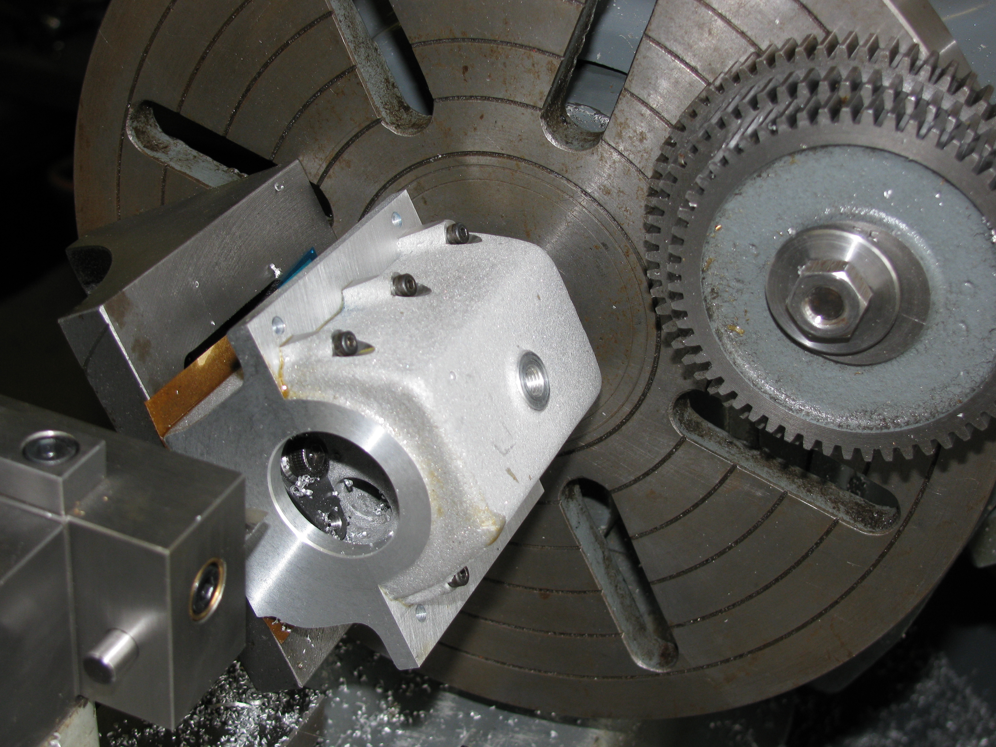
Mounted on an angle-plate on the large faceplate, the crankcase has to be clocked-up three ways, firstly a fore-and-aft check on the bolting face, as I know the top and bottom faces are not quite parallel. For the best work it would be a good idea anyway, in case there is any error in the angle-plate. I typically find I need a thin shim under the back end. This is the blue material, from a pack of plastic shim from RS Components. Secondly, the datum edge is used to square-up the crankcase and finally the button can be set to run true. Actually I found this button, made I think from ½″ silver steel without turning the outside, not brilliantly round and hard to set true. Getting the angle-plate to move a tiny amount in the right direction can be frustrating. My lever DTI is has 0.01mm divisions, and I am not happy unless I can get within one division. After balancing the job with some weight on the faceplate, I made a final double-check that the crankcase was still square and bolted the sump in place.
It needed about a thou feed to cut all round the end of the crankcase. I took 10 thou off, bored the hole to size and chamfered the outside. As the balance was not very good and the chipboard flooring is a bit wobbly under the lathe, I kept the speed down to 200 rpm.
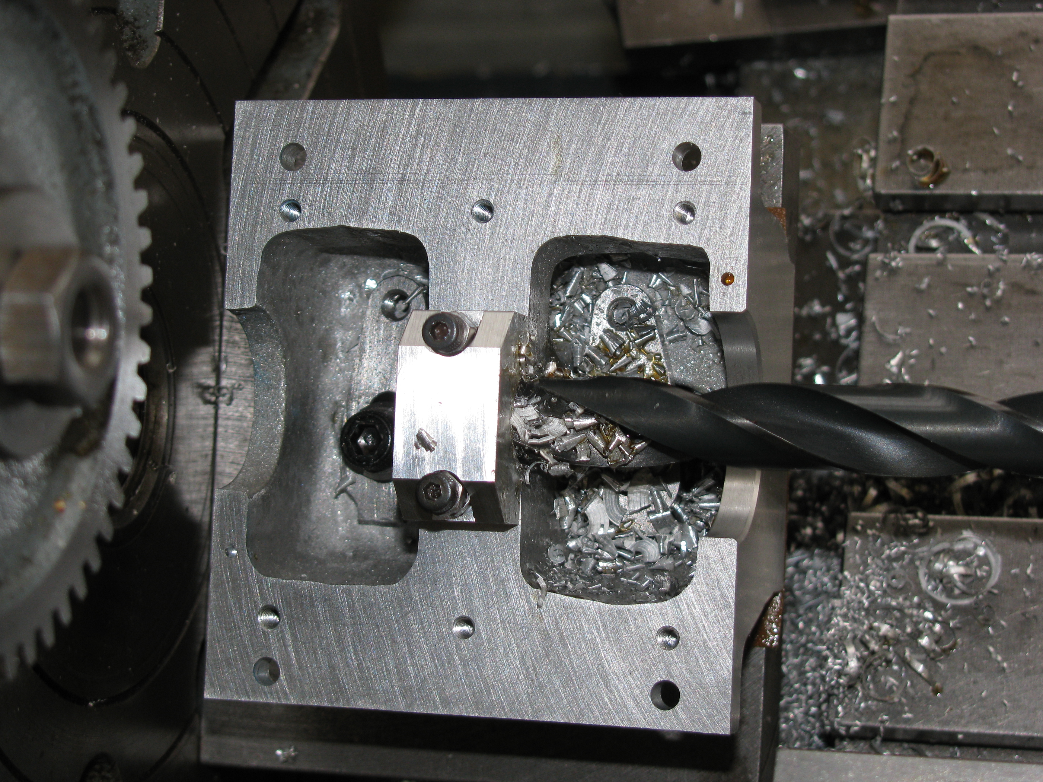
Next, I took the sump off and fitted the centre bearing cap. I centred it, drilled it to 10mm in a couple of steps, and then rough bored it 75 thou under size. (5 ¼ hours)
2010-08-04 - Finishing the centre bore
I finish turned the bore, to a size of -0.0005″, machined the face to the correct depth from the outside face, and stripped down the setup. (1 hour)
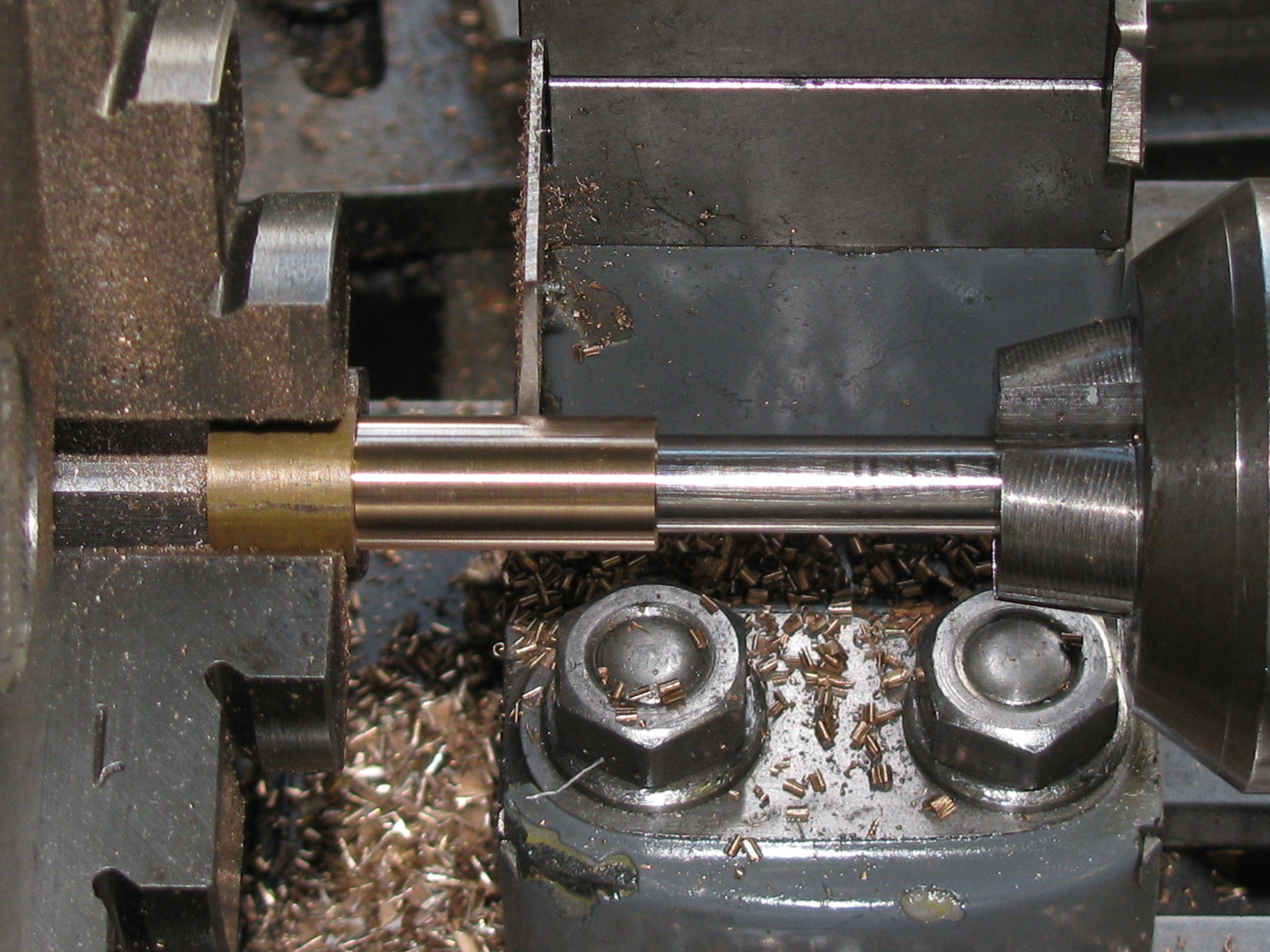
2010-08-09 - Stub mandrel
Today, after a little exercise making the sump drain plug, I turned the a steel stub mandrel for mounting the crankcase assembly for working on the timing end. The stub for the centre bearing measured spot-on 0.500″, and the bearing cap and crankcase grip it nicely without being forced or leaving a a gap.(2 Hours)
2010-08-10 - Boring timing end
After facing the crankcase to final length, +0.001″, and boring for the bearing housing spigot, to size, as best as I can measure it, the last job was to machine the back face for the centre bearing. Using my second-hand depth micrometer, I had some difficulty getting the dimensions to add-up. I found the 1-2″ depth rod reading wrong, by 0.0008″ against a gauge block, which is not good enough. I need to check and adjust the whole instrument. Allowing for this I still had a discrepancy of 0.0015″, which I put down to the centre bearing face not being seated properly against the face of the stub mandrel. I decided to work to the depth measured from the end of the crankcase. The result is that the bearing cap is a shade over a thou too wide, which is no great problem as the bearing flanges need to be made to sit snugly on the cap. (2 hours)
2010-08-18 - Cylinder register holes
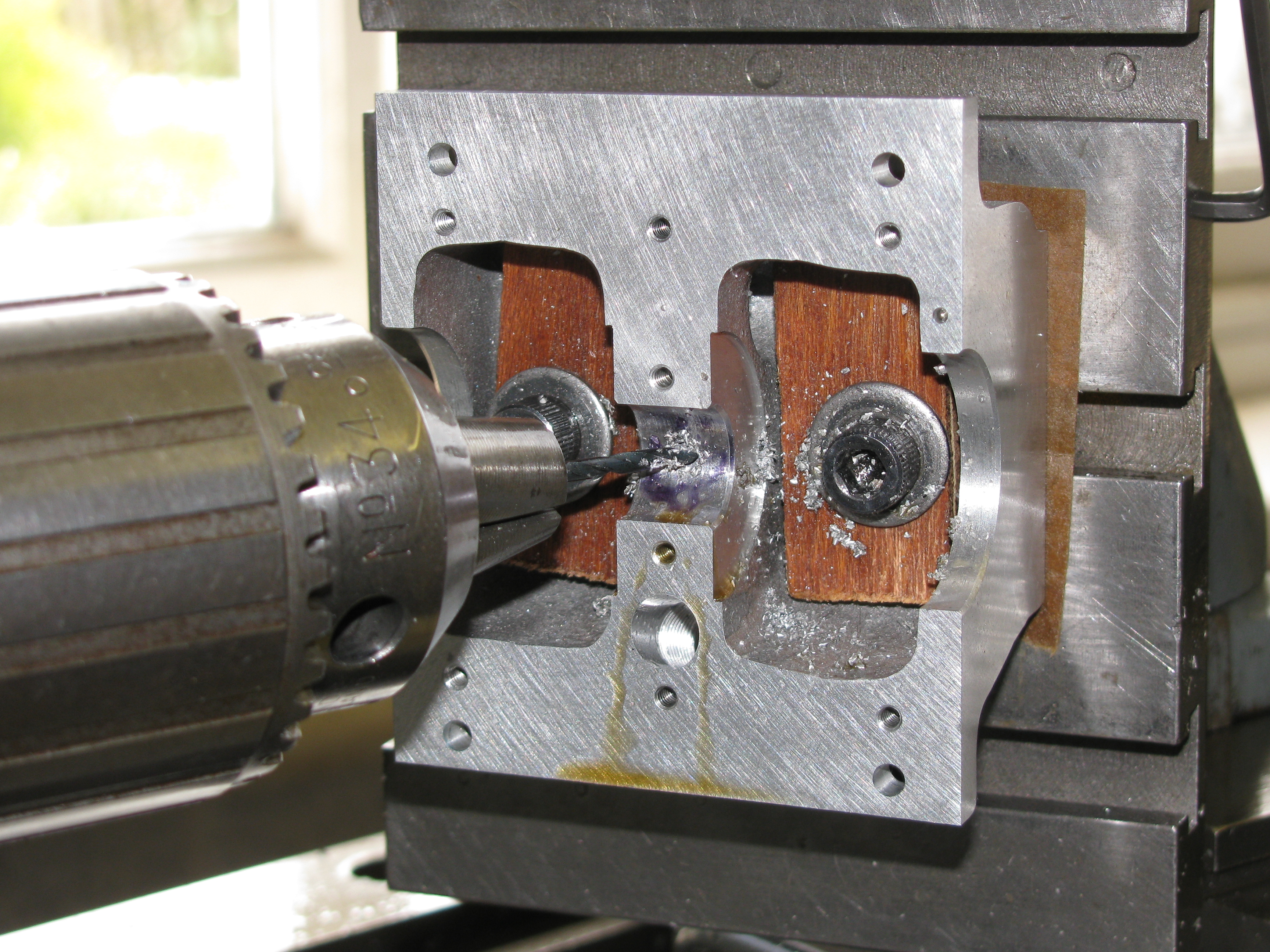
After marking the centre bearing cap and crankcase with dots for correct orientation, deburring it and trimming the retaining screws to 7⁄16″ long, I turned up a gauge for the cylinder seating holes. I decided to do all the holes in the top of the crankcase by co-ordinates on the vertical slide rather than setting up on the faceplate. Working this way you need a boring head, of course. On my drawing I had originally set out the holes from the centreline, but decided it would be better to work from one datum end so I re-dimensioned it that way. It was quite tricky to find a way of fixing the casting to a vertical slide so that it could be set up square and all the holes could be got at. I went through a number of ideas before settling on bolting through one cylinder hole while working on the other, with an additional clamp on the flange to give peace of mind. The cylinder seating holes were bored, and the tappet holes drilled to 5.7mm. (6¾ hours)
2010-08-21 - Tappet and cylinder mounting holes
Judging from the surface finish of the cylinder register holes, I do not think I can achieve the result I want for the tappet holes with fine boring. The tappets need to be a pretty good fit if the holes are to last. I think a bored hole would soon wear to too sloppy a fit, which might continue to deteriorate rapidly because of the side load. At least with a flat-faced tappet the load is all one way. Equally, Westbury says the length of the hole is not enough for reaming, and I am not going to risk it. It occurred to me that a 'ballized' bore might be a good way to get a smooth, accurate, work-hardened hole in the alloy casting. I tried carefully drilling a 6.3mm hole in a scrap of alloy and pushing a ¼″ steel ball through it using the drilling machine quill as a press. In spite of the 2 thou interference I measured, the ball went through easily, leaving a good surface finish with no galling and the hole still 1 thou undersize. I like the idea of a slightly undersize hole as it means that the tappets could be lapped to fit after hardening.
I found that cutting speed made little difference to the surface finish of the tappet holes, but made them as good as I could get, with cuts of 10, 2, 1 and ½ thou in each hole, taking the last cut at 80 rpm.
Still looking for every possible cause for misplaced bolt holes, I checked my 2.2mm 6BA tapping drill. The end was horribly blunt. All I have for drill sharpening is a Reliance grinding jig and, while it is pretty good on larger drills, 2.2mm is really too small for it. The result was no more than OK, so pre-drilling with a good smaller drill will be the order of the day until I get a replacement, or a better way of sharpening small drills.
Once the drilling was done and the job removed from the lathe, I pushed the ¼″ ball three times through each of the tappet holes, using graphite grease as a lubricant. The result looks almost as if the holes were polished. I tapped the eight cylinder mounting holes in the Pillar Tool.
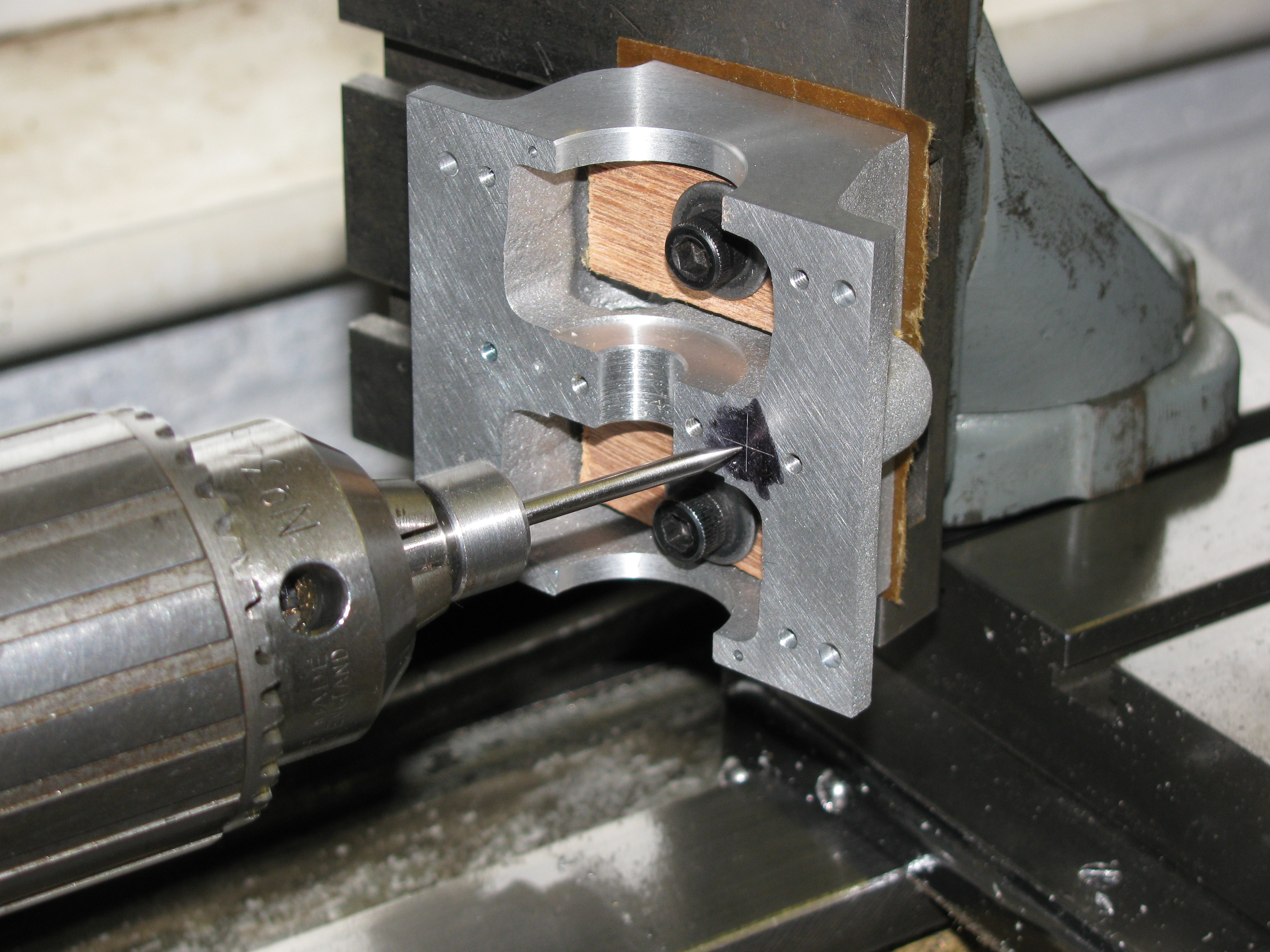
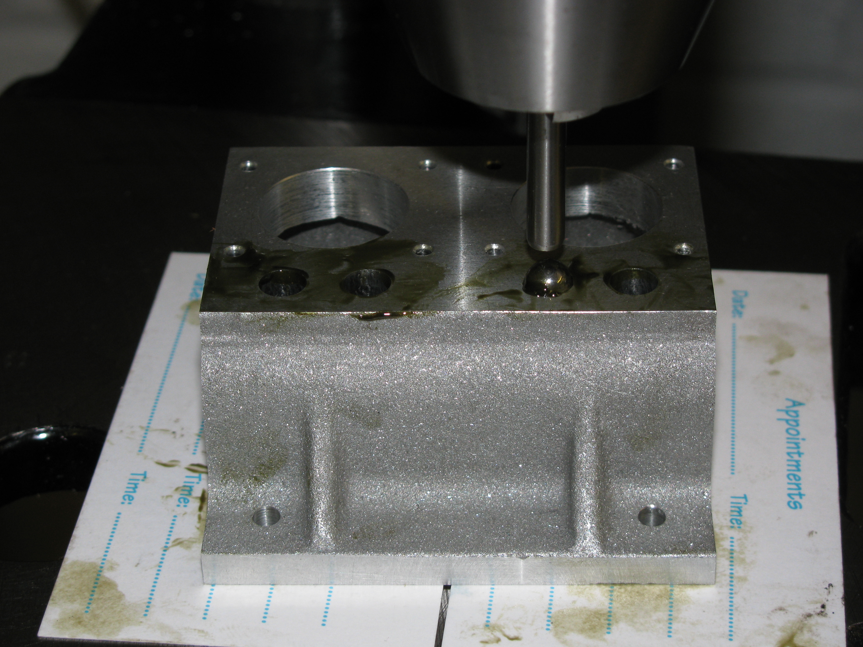
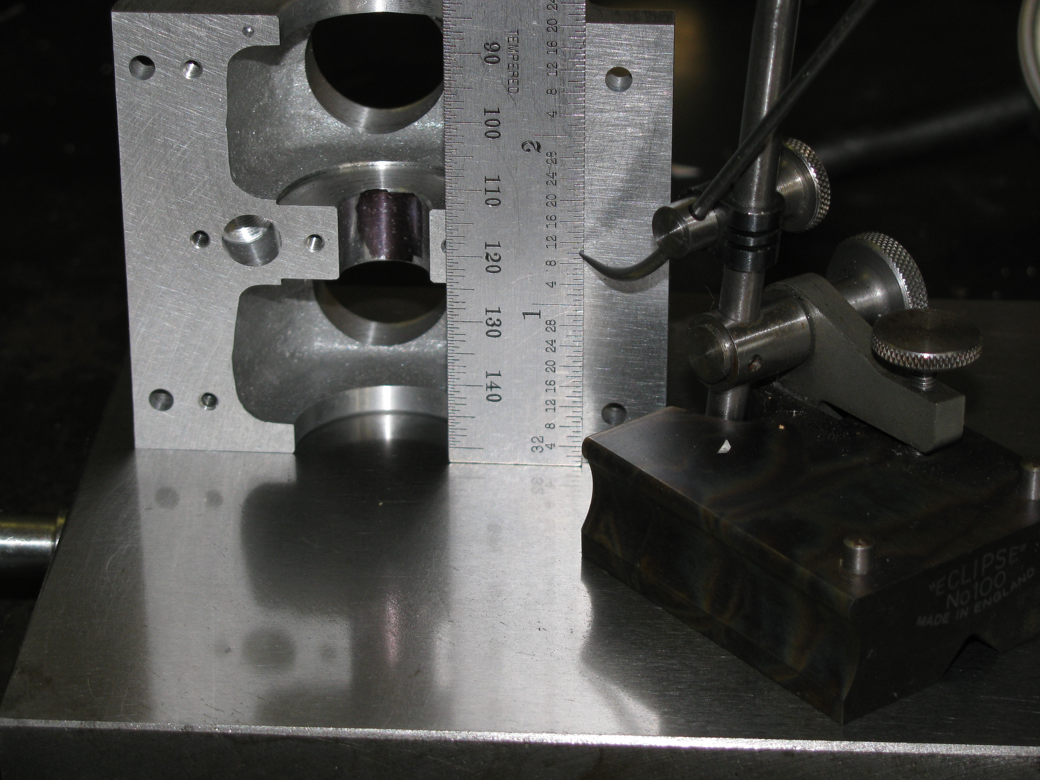
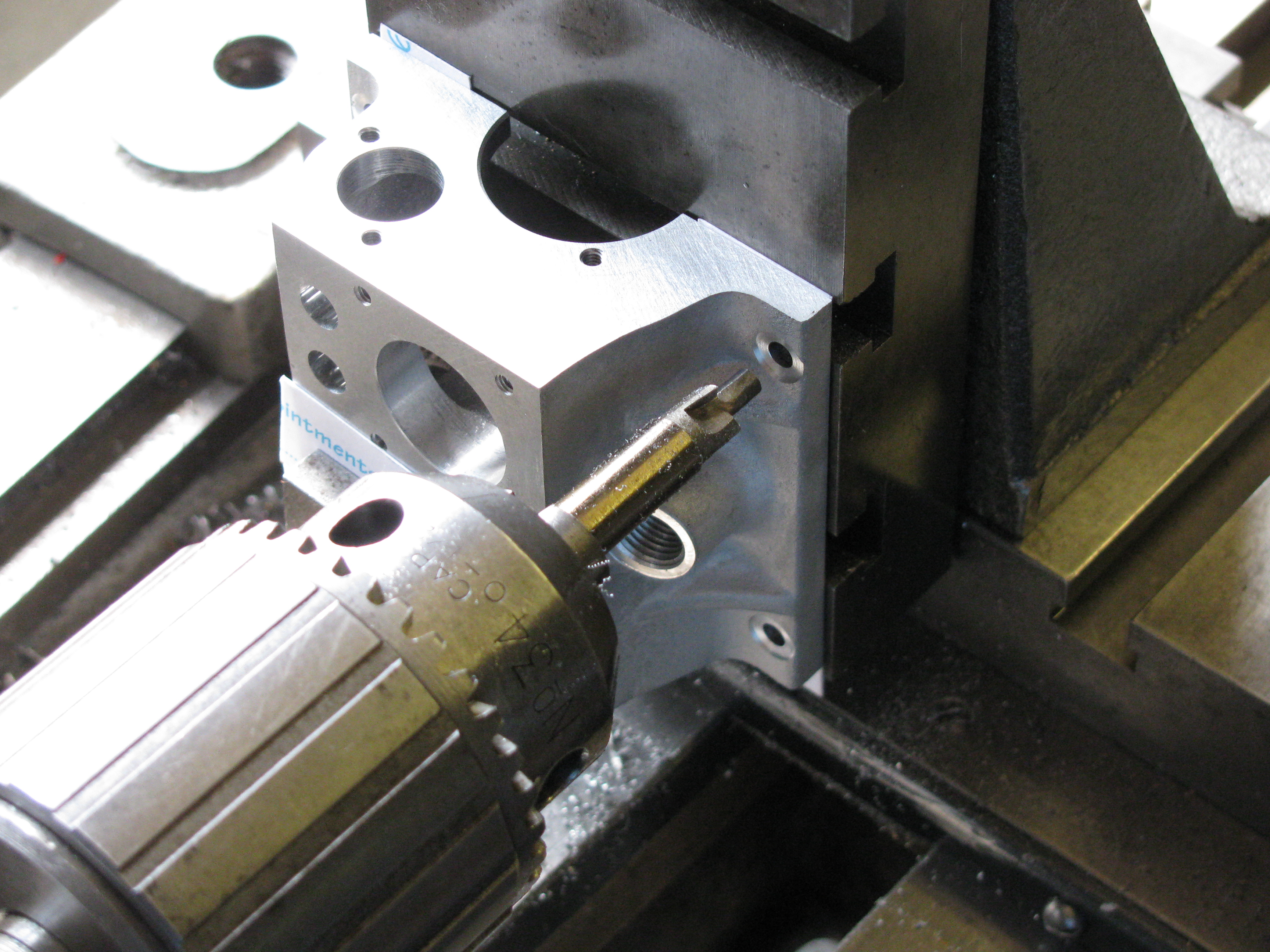
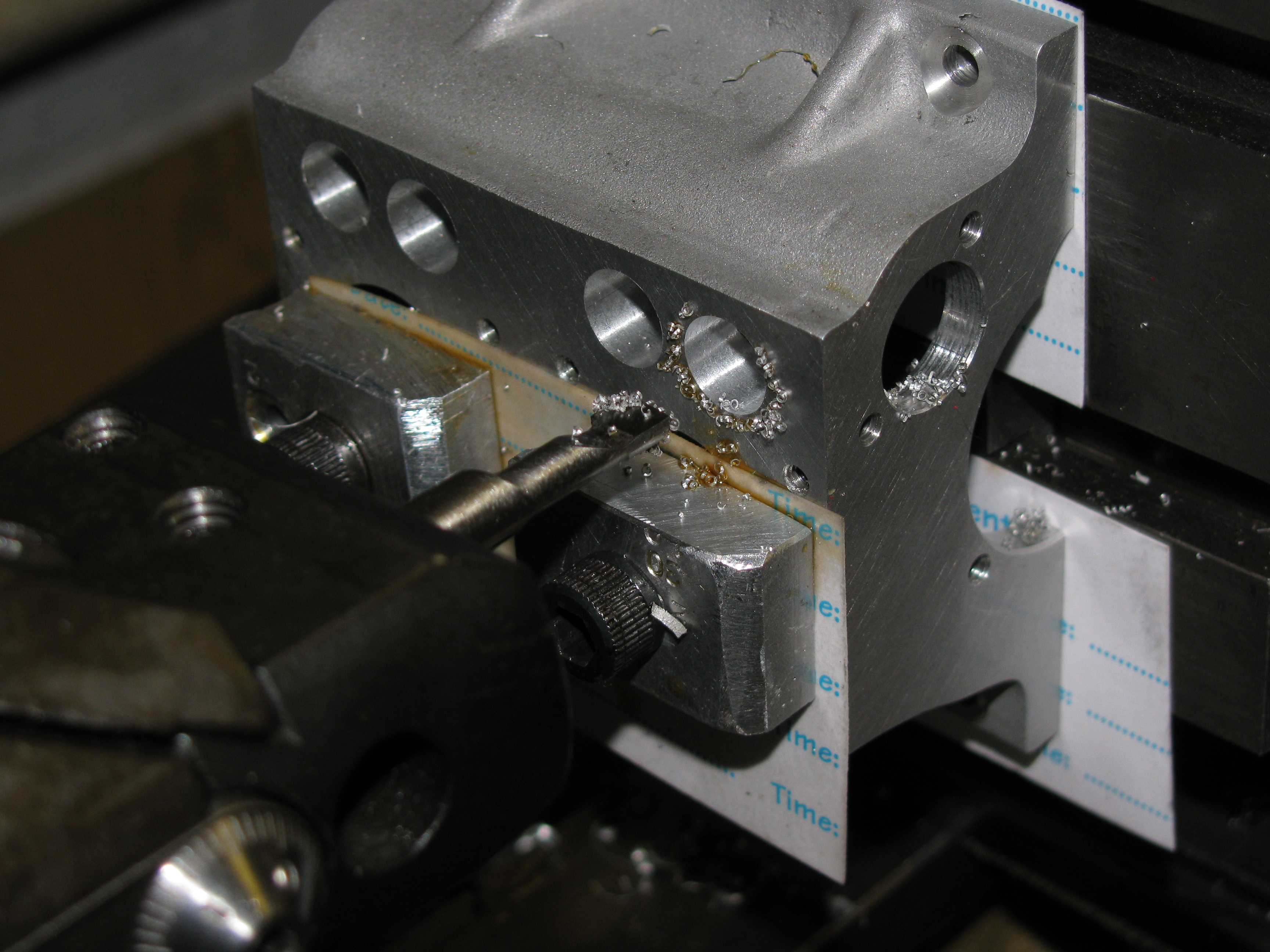
The last job today was marking out and drilling the oil filler hole. I marked out on the underside machined face to get the correct lateral position of the hole. After lining up with a 'sticky pin' wiggler, I cut a shallow pocket with a slot drill to present a square face to the drill, centre drilled and drilled an undersize pilot hole. This hole emerged to be pretty nearly central in the external boss on the casting, so the hole position will not need to be adjusted when working from the top. (6¾ hours)
2010-08-22 - Filler hole and oil holes
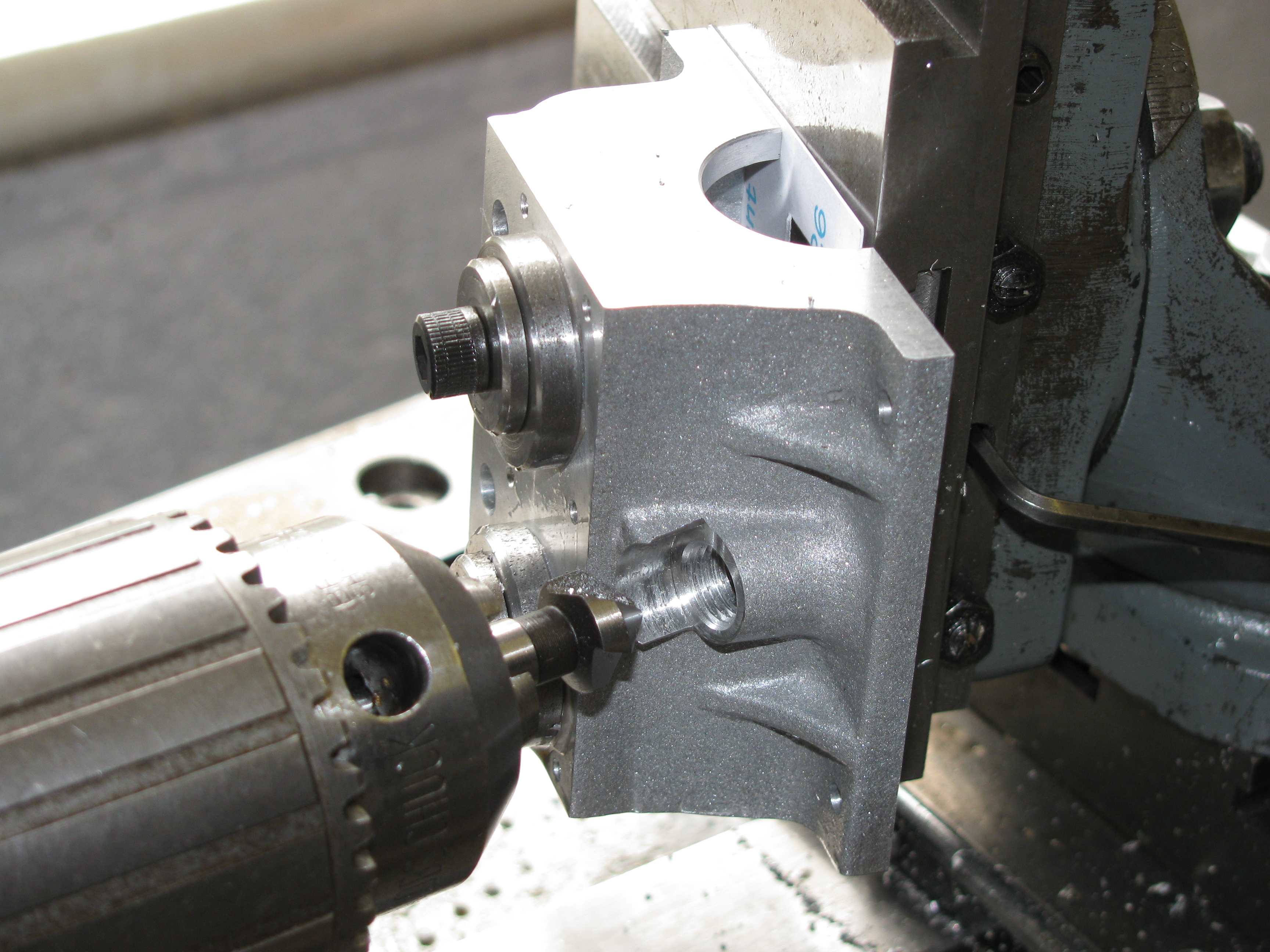
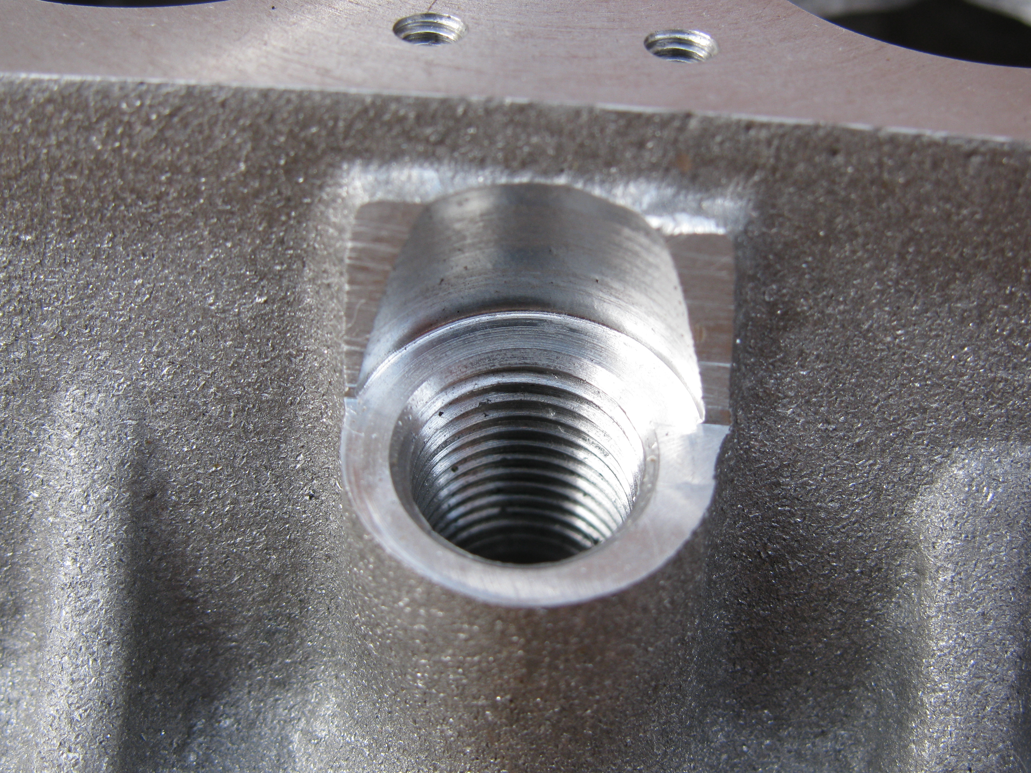
Working on the oil filler hole from the top, I opened it out using a 5⁄16″ long-series end mill and cut the seating with a ½″ slot drill. I found that when slacking the locking screws on the vertical slide, for a traverse over the boss face, it moved a bit, making it a bit tricky to maintain a clean seating for the filler neck. Evidently the slide could do with adjusting. I also managed to forget the dial settings for the centre of the hole, which did not help. The pocket in the crankcase was opened up a little using the boring head, and the hole drilled, tapped and chamfered. Although I had to use a slightly undersize tapping drill, the tap went in very nicely.
In planning the job I knew there would be some cleaning up to do on the casting, but had not really thought about the quite large 'wings' that would be left above the hole. These have been roughly filed down for now, and I will need to work out how best to blend in to the cast and machined surfaces.
I had thought the centre bearing oil holes would be tricky to do, but actually I did not have any problem. With an angled hole I always mill a pocket to give a square face for drilling. In this case it was doubly important for the second hole. I thought I had a 5⁄32″ long-series slot drill to counterbore the holes from the top for better oil collection, but the result from using a 3.5mm one looks fine. (3½ hours)
2010-08-23 - Setting out camshaft holes
It might be possible to bore both ends at the same setting on the faceplate, though it would probably be better to set up on the boring table and use a boring bar between centres. I am going to use toolmakers buttons to set each end up separately. This may be more time consuming, but I am more confident of success. I marked out, drilled and tapped 6BA holes at each end of the crankcase for mounting toolmakers buttons to locate the camshaft holes at each end. (½ hour)
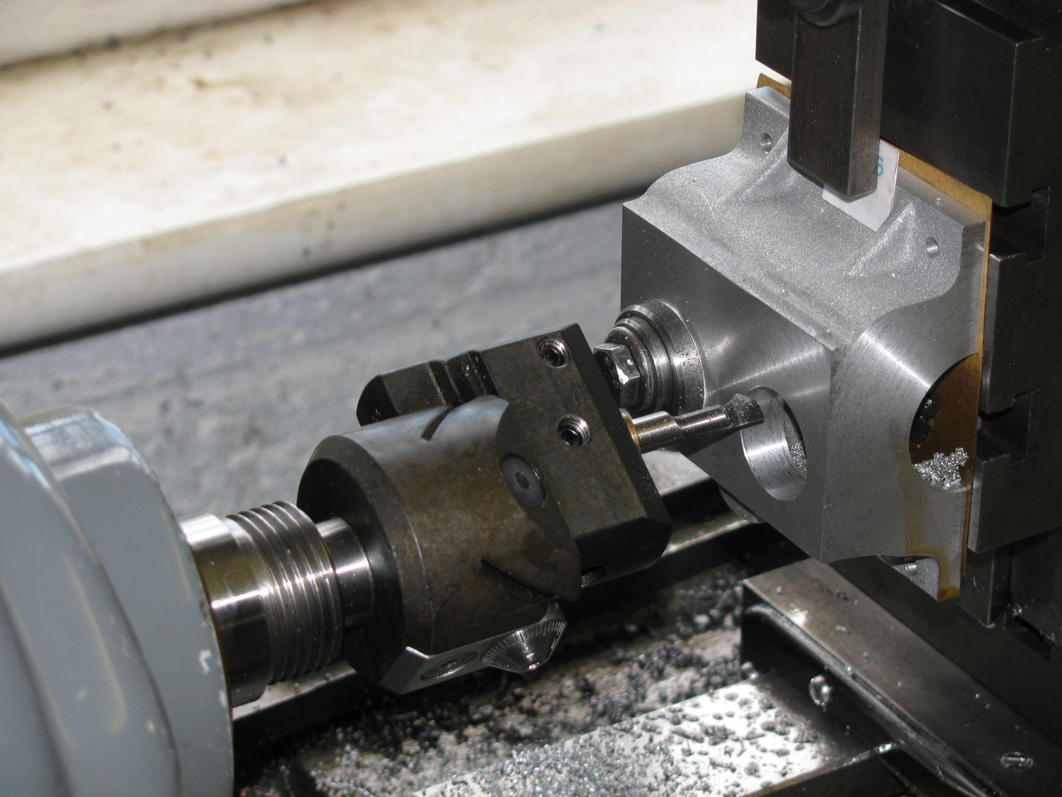
2010-08-28 - Flywheel end camshaft hole
After the difficulty experienced in setting up the crankshaft hole with a toolmaker's button that turned out to be not quite round, made a new one for this job. I also made yet another pair of clamping plates for holding the casting without encroaching to much into the camshaft space. The button was positioned in the normal way with slips on the surface plate. That was the easy part of setting up. The first problem was to find a way of getting the button somewhere near on centre with more than one bolt holding the angle-plate on to the faceplate. In the end, I found I needed a thick packer between casting and plate. Getting the casting square both ways was not that difficult, but setting the button to run true was a right pain. The blasted angle-plate just would not shift in the direction in which I wanted it to go. Most of my gentle taps made it move either not at all or far too far at right angles to the intended direction. Sometimes this is easy and sometimes it isn't. I don't know why.
(For this kind of work, I have two Thor soft faced hammers. One has nylon inserts and on the other I replaced the worn out orange plastic inserts with brass. This is very effective. The direction you need to shift things would often involve hitting the job itself, which is fine for a rough lump of iron, but not for these delicate surfaces. I keep a piece of ½″ brass bar, about 4″ long for reaching behind the workpiece.)
Today, boring the camshaft hole was not plain sailing either. Opening out the tunnel would have been easier if most of the metal taken off had not been from the clamping plates. And in machining the bearing seat the tool was not playing ball. The hole has ended up a smidgin over size and with a detectable roundness error. The latter could be a matter of balancing the spindle, which I thought I had done reasonably well, or slight variability in the metal. Anyway it is well within requirements for a press or Loctite fit (I haven't yet decided which). (6¼ hrs)
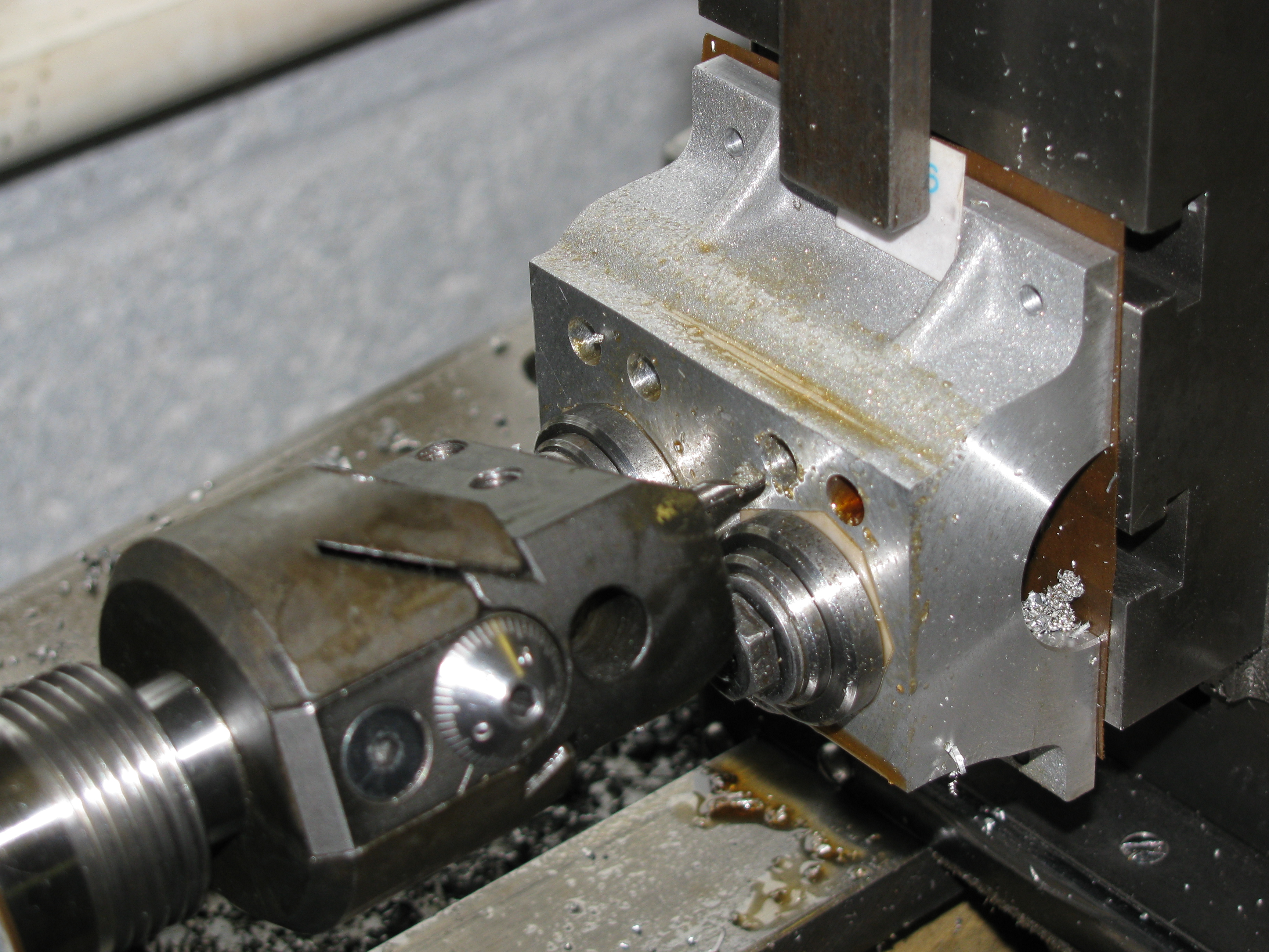
2010-09-04 - Timing end camshaft hole
Setting up the camshaft hole at the timing end was much as before, with the same difficulty in getting truth, but the boring went well and this hole is closer to size. (1¾ hrs)
2011-04-05 - Fettling
In an odd half hour I got quite well on the way with reducing the lumps above the breather hole. Starting with a sanding drum in the Dremel, and rapidly moving to riffler files, it still needs a bit more removing before it will be ready for finish sand blasting. (½ hr)
2011-04-11 - More Fettling
More work on the crankcase round the breather boss, using mainly rifflers, but also diamond burrs held in the fingers, and wet-or-dry, and with the aid of a headband magnifier, has now got it ready for sandblasting, I think. If I wanted to do an exhibition finish job on this engine, which I don't, I think I work up all the cast surfaces to a smooth, polished finish before sand blasting. Soon, I will need to solve the problem of protecting the machined and lapped top, bottom and end faces, so that only the side elevations are are exposed to the blast. The wide bolting flange needs trimming before that, though. (1 hr)
2011-04-26 - Flycutting

There are any number of ways to set the casting up for cutting the camshaft side mounting flange back to match the other one, but it seemed to me that the simplest was to bolt it to the boring table and fly-cut it.
Machining the flange cut into the cast webs, and I needed to do some hand work, with files and wet-or-dry as before, to make the surfaces look like cast ones again.
Satisfied that the casting was ready for sand-blasting, I started work on a box to protect the four machined faces from the abrasive, and made a stepped washer with a thin bevelled edge to protect the machine face of the oil filler hole.
The arrangement of the casing needed a bit more thought, so I diverted attention to annealing a piece of 5⁄16″ silver steel for making a spot-facing cutter for the engine mounting holes. (4 hrs)
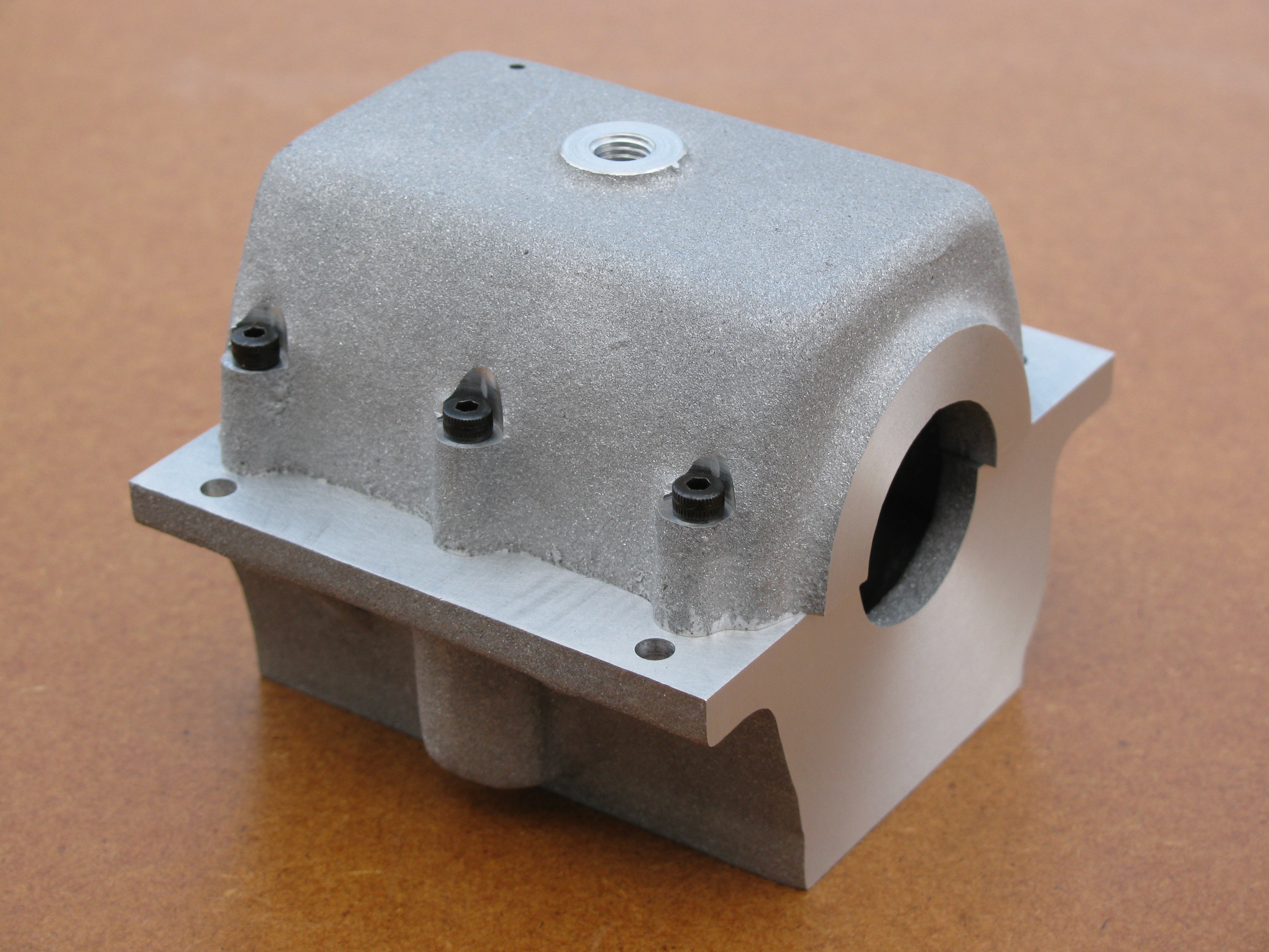
2011-04-27 - First blast
I finished the four-sided sand-blasting protection box, making it out of MDF offcuts clamped together with various screws and studs through suitable holes in the casting. I don't have a sand-blast cabinet, but I have use of one a couple of miles away. I was a bit worried about abrasive getting to the wrong places, especially as I had forgotten to put my intended layer of grease between the casting and the box to seal any cracks. It actually worked fine. The surface of the MDF was well roughed up in places, but not enough to let the sand in. After dismantling the box, giving the crankcase a good blow over with the air gun, and a thorough wash in hot water, the resulting surface was just as I had hoped. All the filing and rubbing blended in to an even matt surface. Nice. (¾ hr)
2011-04-30 - Spot-facing
In the morning I made a 9⁄32″ spot-facing cutter for the engine mounting holes, set the crankcase up on the vertical slide and cut the seatings. One of them just cut away the edge radius on the flange; not as wished, but as expected. With 9⁄32″ washers in the spot-faces it will hardly notice. (3 hrs)
Later in the day I started work on the camshaft.
2011-11-22 - Idler Stud
The next job was to make the hole for the idler stud. This passes through the Timing Case and Bearing Housing, and a clearance hole is needed for the nut, lying on the joint between the Crankcase and Sump. This is described in the Timing-End Bearing Housing section.
2011-11-23 - Reworking the tappet holes
As explained here, the design tappet diameter is too small for the design cam profile, and the crankcase casting is not the ideal thickness at the tappet holes, so despite having carefully ballized them earlier, I have bored out the holes to 11⁄32″ and fitted 9⁄32″ bore bushes.
As I was quite pleased with the way the holes had come out originally so I used each one as its own datum rather than trying to align on the (now sandblasted) datum edge of the casting. After clocking up and drilling out the bulk, I bored each hole to size using the boring head and creeping up on the final size with 0.0005″ cuts. The tool was cutting nicely and produced a good finish.
After stripping the job down and giving the crankcase a good wash in paraffin (kerosene) I started work on the tappet bushes. I parted off a pair of lengths of bearing bronze, each enough for two bushes and a chucking piece. I faced, turned the OD to 0.01″ over size, then centred, drilled and bored (nicely parallel for once, as it was not to be a finished bore) to about 0.004″ under size and reamed, at 600 rpm. I finish turned the whole diameter to an easy push-fit in the bores, put a small chamfer inside and out and parted off slightly over length, and repeated for the second piece. A rod in the tailstock drill chuck caught the quite delicate bushes as they came off. I gripped each one very gently to face the other (upper) end to 0.002″ over final length. (4¼ hours)
2011-11-26 - Tappet bushes
To fit the first two bushes I gave them and the crankcase a hot-water wash and fixed the with Loctite 641 Bearing Fit. I rested the crankcase upside down on a piece of MDF with two cigarette papers between, so that the bushes would end up very slightly proud of the surface. While these cured I machined the second pair and then Loctited them as before. While I was at it, I also Loctited the front camshaft bearing in place, holding it lightly with a bolt through the camshaft tunnel while the adhesive went off. This happens very quickly as the cure is catalysed by copper. While this cured, I cleaned the lathe and had a tidy up, then lapped the bushes flush with the top face of the crankcase, which I need to remember is now 3 thou short of nominal height. With a final wash, I think that is the crankcase finished. (3 hours)
.