
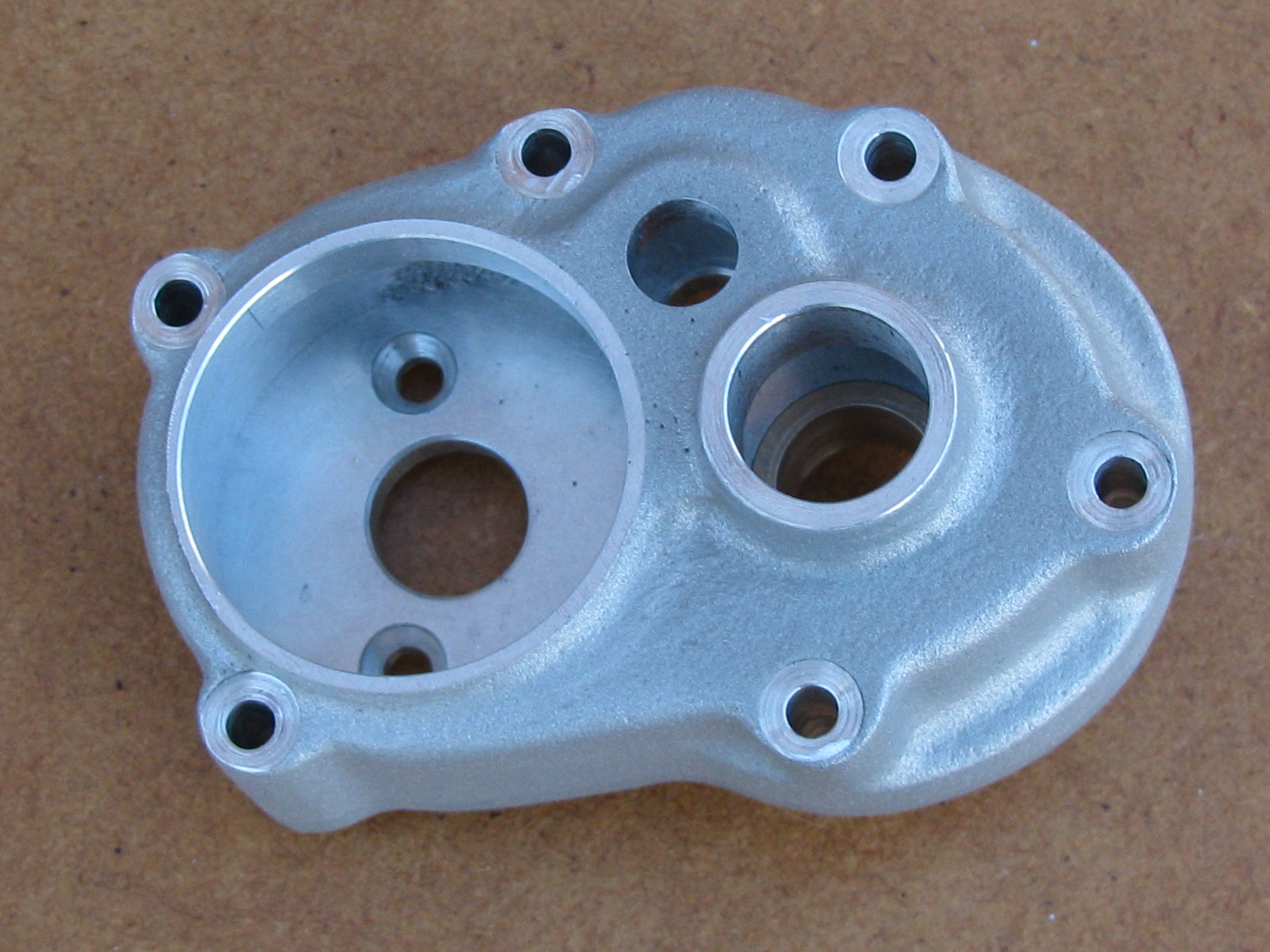
Timing Case

The machining allowance on the bolting face of this casting is quite small. Care will be needed in setting it up to try to get the unmachined parts of the outer face level. For the second operation it should be set up with the crankshaft boss running true, as there is not much metal round it and any eccentricity would be conspicuous in the finished part. The crankshaft boss can be faced and bored to about 5⁄16″ as a datum. Transferring the set-up to the dividing head, the three lower bolt holes can be set out on a pitch circle, the angular disposition being determined by the casting and the holes drilled and spot-faced. It may also be desirable to mill the lower circular periphery to ¾″ radius, but if so it wants to be done in place on the bearing housing. While it is on the dividing head, the camshaft radius can be brought to centreline and the centre position found by equalising readings on either side of the distributor boss. This hole can then also be bored 5⁄16″. Using this hole as a datum, the three upper holes can be set out. This could be done attached to the timing bearing housing or separately. It makes sense to do as much as is convenient with the two parts together, located by the dowels.
I am going to position the crankshaft and camshaft holes on this part initially, to ensure they are located well in relation to the finish cast surfaces. I will then transfer these holes to the Timing-End Bearing Housing, after the two parts have been dowelled together. These holes in the Bearing Housing will be used as datums for setting it up for finish machining, and finally the resulting hole positions will be transferred back to the Timing Case.
The solid state ignition will require an arrangement quite different from a contact breaker, and this needs to be designed before the timing case can be completed, and will depend on whether mechanical or electronic advance is used.
2010-08-23 - Bolting face

I set the casting up in the 4 jaw using the tops of the bolting lugs to get the casting level. For this kind of job it is easier to do as much as possible with the chuck lying flat on the bench. The first cut over the bolting face produced a very rough finish. Trying a different tool, and taking another 10 thou cut, the result was nearly as bad. Running out of metal to take off, I went for a belt and braces approach, using yet another tool, dropping from 400 to 200 rpm, and taking a cut of 5 thou. The result was a smooth, if rather odd looking surface, which a light trial lapping soon had flat. The bolting face to bolting lug dimension has ended up a few thou over the nominal ½″, but the result will be fine. (1¼ hours)
.
2010-10-02 - Casting induced cock-up

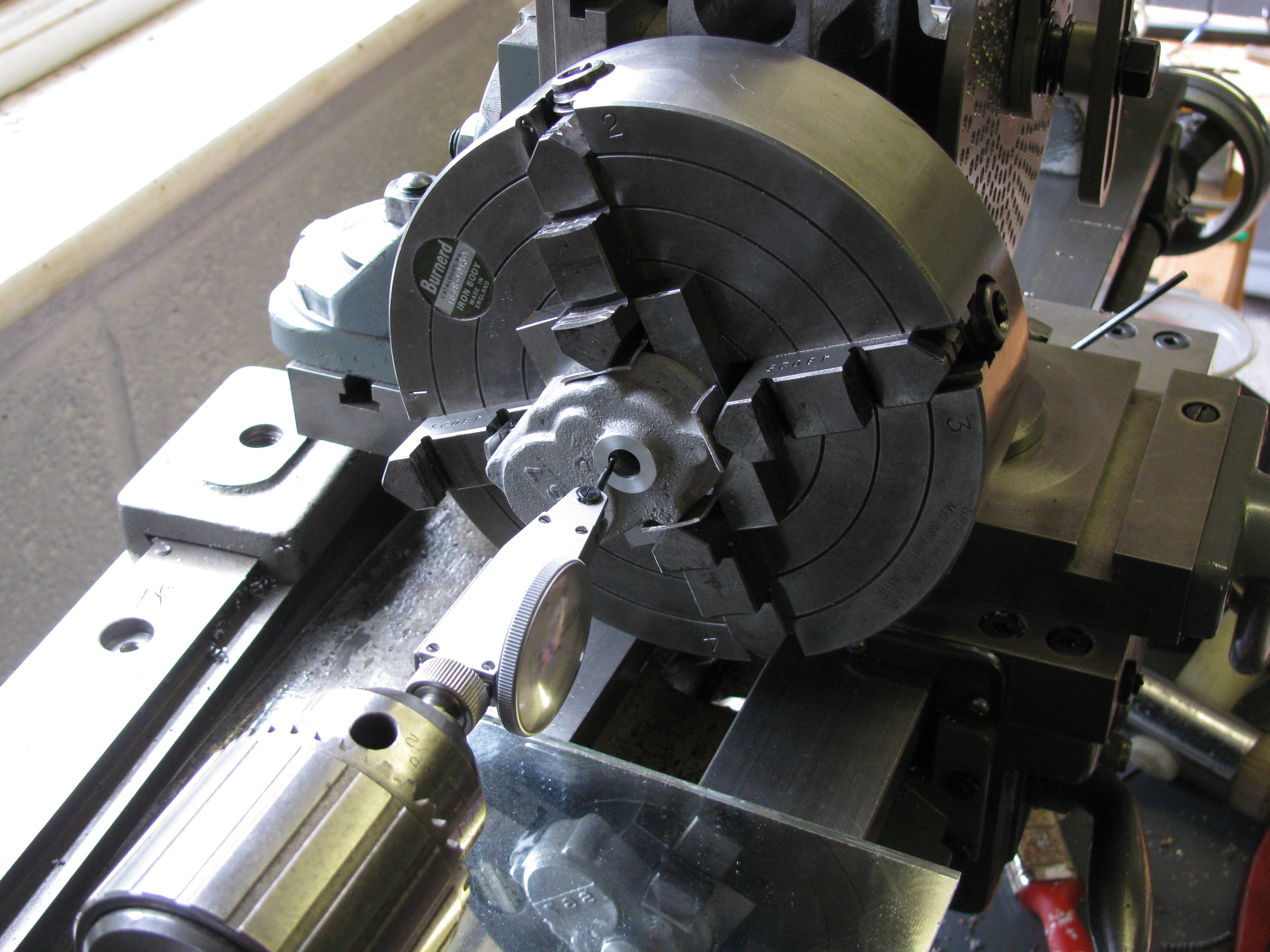
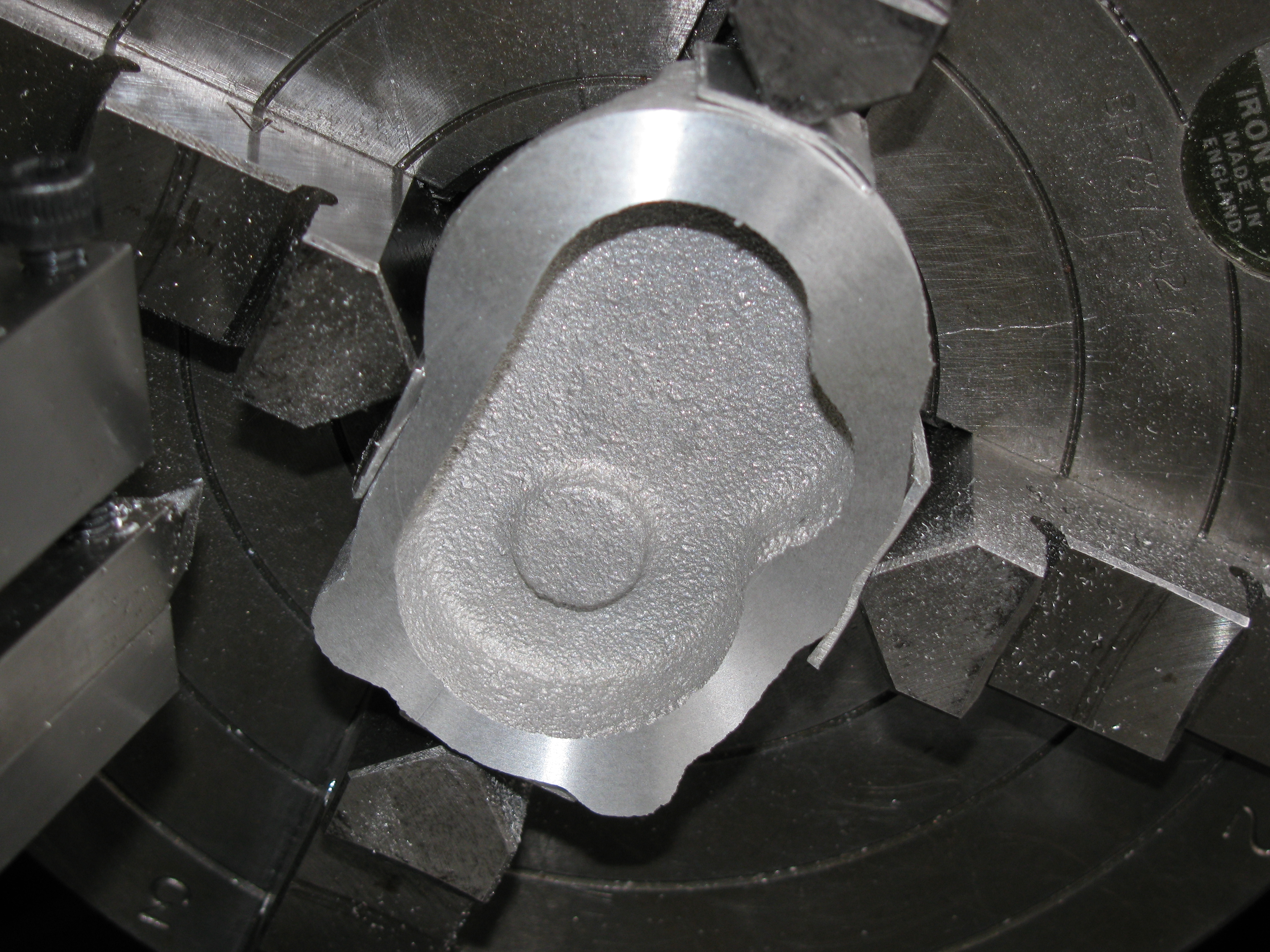
Setting up the timing case for machining the datum bore and the lower bolt holes with the rather oval crankshaft boss running pretty true. Firstly I faced the boss, about 6 thou short — I have not had a depth micrometer long, and if I am not very careful I can still get confused by the back-to-front reading. I drilled, bored and experimentally reamed it to 5⁄16″. The finish of reamed hole was just about OK.
Next, the chuck was transferred to the dividing head, set up on a vertical slide, for drilling the lower bolt holes. It would have been easier to use a toolpost mounted milling & drilling spindle, but I do not have one. Now, the drawings in the original article do not give a pitch circle radius for these holes, but they are shown on the bearing housing drawing as coming extremely close to the edge of the crankcase spigot. Having reduced the spigot by 1⁄16″, I had decided to work to 1¼″ pitch circle. This allowed a nominal 1⁄8″ lug radius within the 1½″ overall diameter and a still skimpy 3⁄32″ from the centre of the tapped hole in the crankcase to the spigot bore. The angular position to centre each hole on its cast lug would be found by eye.
On setting the cross-slide over 5⁄8″to the chosen PCD, it immediately became clear that I would not be able to get the spot-faces on the bolting lugs to clean up. The draw on the casting, and the position of the boss for the crankshaft in relation to the periphery, meant that with the chosen centre, the hole through the lowest bolting lug would come too close to the edge, not allowing an adequate spotface. There was no scope to reduce the pitch circle, so the only other thing to do was to move the crankshaft centre away from the offending lug. A movement of 1⁄64″ would be enough. This would allow the crankshaft hole to be re-machined and as there is sufficient metal, a cut to be taken round the outside of the boss to disguise the eccentricity of the cast surface. This has the bonus of allowing a blend radius to the broad machined face. So I duly moved the casting over 1⁄64″ and drilled the holes. What I had forgotten to do was to reposition the cross-slide by a similar amount, so all the holes were drilled 1⁄64″ too close to the new centre.
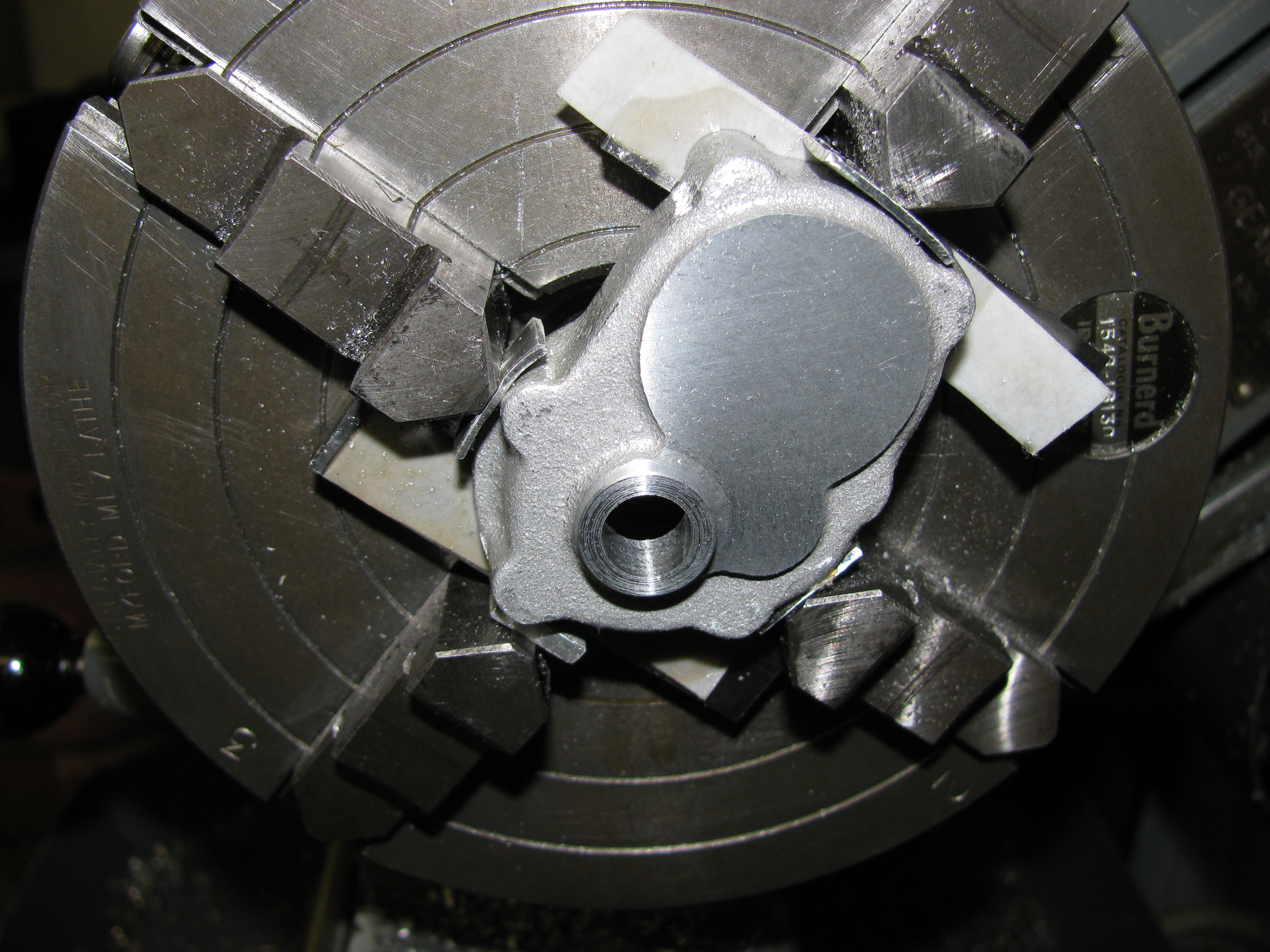
I had intended to line up the camshaft hole with this set-up, but as the job had been shifted I had lost the true running datum surface. So I put the chuck back on the lathe spindle, opened the crankshaft bore, on its new centre, to 3⁄8″ and machined the broad face to size (+½ thou). The bore finished quite nicely with a boring tool, despite finding a small cavity in the casting. The face and boss took a good fine dull finish for the most part, but with a bit of a shine developing near the nose.
Returning the chuck and job to the dividing head set-up, the 3⁄8″ bore was clocked-up to the lathe centreline again, set over 0.9525″ on the cross-slide dial, and rotated until the machined face lined up with a stub of bar held in the 3-jaw chuck. In this position an alignment guide hole was drilled and reamed ¼″. (6¼ hours)
2010-10-09 - Timing Case No 2

I decided that having the tapped holes in the crankcase and sump just 1⁄64″ from the edge was not really the standard of workmanship I am trying to achieve, so I approached Hemingway Kits for a spare casting, which duly arrived by return at a reasonable price.
When I checked the sheet drawings, I noticed that the PCD for the holes is indeed specified there, at 15⁄16″. As I am making the bearing housing spigot smaller, I am working to a pitch circle of 19⁄32″ this time, same as at the flywheel end. The across-corners size of a 6BA nuts is 0.223″, so a spot face of a little less than ¼″ is OK, and I have decided on 6 mm, which I think will just about clean up on the bolt lugs.
The second timing case had a bit more machining allowance on it. After very light filing to get a fair surface on the tops of the bolting lugs so the cast exterior would sit level, it was set up as before and cuts of 30, 25 and 1½ thou were taken at 400 rpm on the bolting face. The tool finish was a good deal better on this one. After lapping the face flat (it did not need much) I set it the other way round and set it up equalising the maximum dial readings at each bolting lug. In this position it looked as though it would be just possible to get the crankshaft boss to clean-up to 9⁄16″. I ended up with the boss just over size, needing a 0.01″ chamfer to completely clean up the edge. Over the face I managed to make the thickness about 3 thou shy, but that will not matter. I experimented with the bore, finding that it machined nicely with paraffin as cutting oil, but my notes remind me not to resharpen the tool immediately before taking the last cut, which may explain the recorded dimension of 0.3755″. (I am writing this up at the end of January 2011.)
2010-10-10 - Drilling
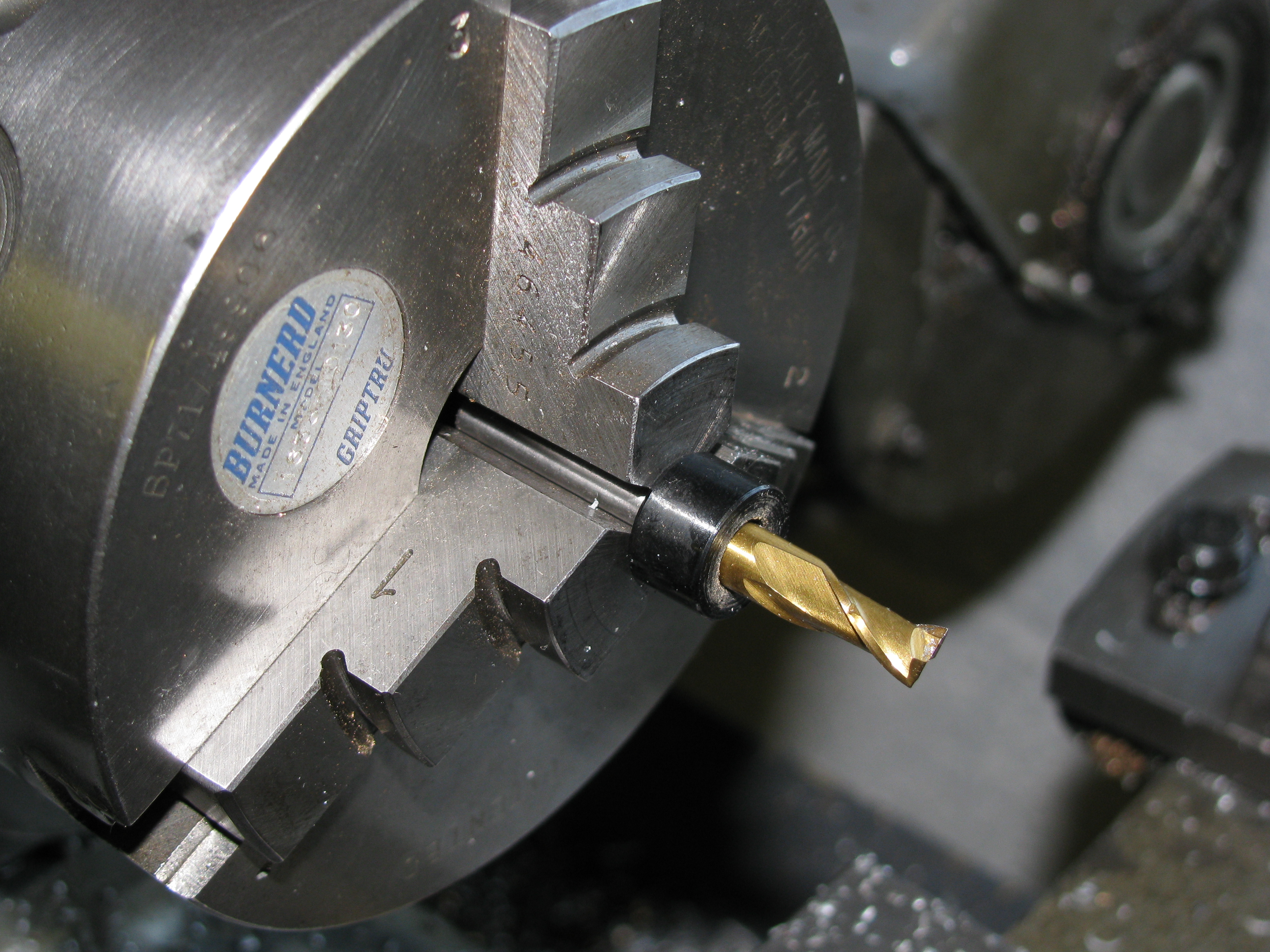
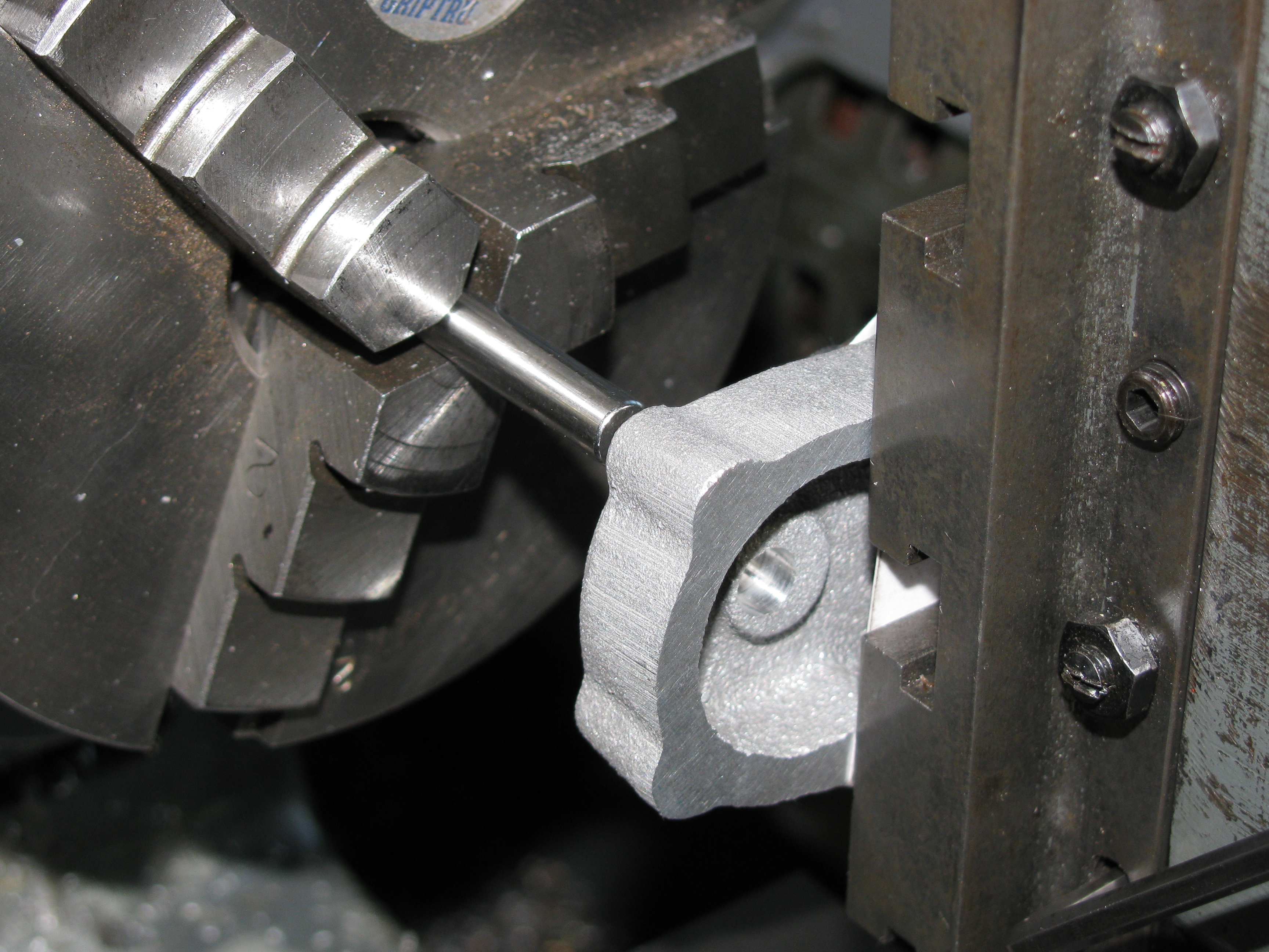
Set up as before on the dividing head, the first job was to drill and ream the setting-up hole for the camshaft to ¼″. This was done just as described above. Using the angular position of this hole as datum, it was possible to record, for possible future use, the angular dispositions of the lower three bolt holes, Also drilled and spotfaced at this set-up. The angle was set by eye, using a 6 mm pin in the chuck to try to adjust for a full spotface. I used a collar on the 6 mm slot drill so that it could be set to a repeatable position in the chuck so as to get the all the spotfaces the same height.
I used a second set-up, fixing the case directly on the vertical slide, to drill the three upper holes. I positioned them purely from the lugs, and the excessive amount of draw on the casting meant that it was again very difficult to clean up the full area of the spotfaces.

.
2010-11-05 - Finishing the crankshaft bore

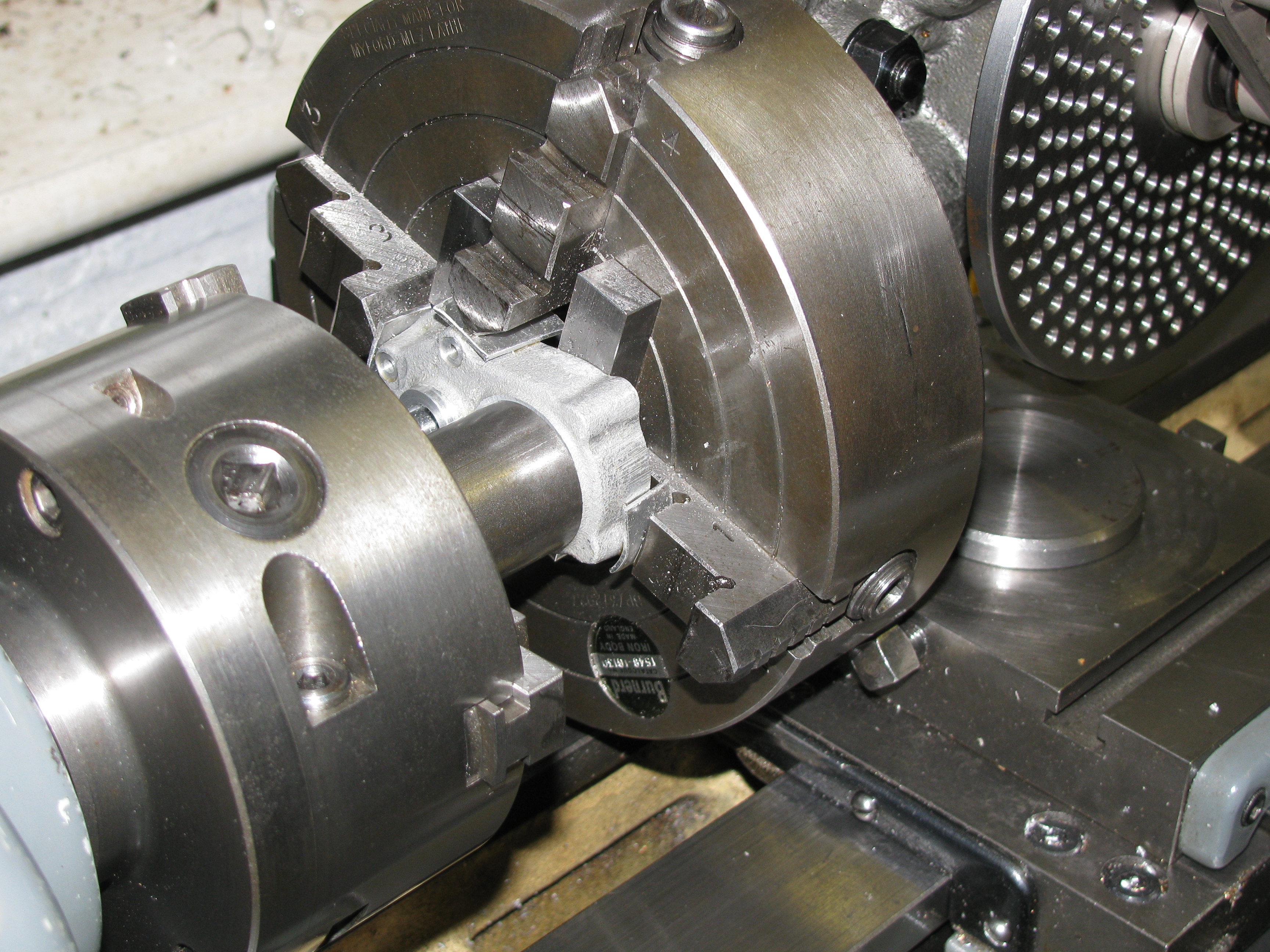
I turned the soft jaws in the 3-jaw chuck to take the crankcase spigot of the Timing-End Bearing Housing and with the housing in place, tweaked the Griptru a tad to get the bearing bore running spot-on. I then fitted the Timing case, using the dowels and 3 bolts (I think the chuck jaws must have been in the way of the other three holes, my notes don't say). The initial hole was out by 0.003″ TIR, not bad. I bored it out to pretty close to dead-on size, and chamfered lightly. For once I have seem to have got a smooth, parallel bore in the alloy, which is good because this one is a bearing surface. Now to take the timing case off and drill oil ports in the bearing housing.
2011-11-22 - Idler Stud
The next job was to make the hole for the idler stud. This passes through the Timing Case and Bearing Housing, and a clearance hole is needed for the nut, lying on the joint between the Crankcase and Sump. This is described in the Timing-End Bearing Housing section.
Once removed from the set-up, the fit on the idler stud could be checked properly with the stud inserted from the inside. It proved to be a shade too tight, and I eased it with the careful application of a hand-held ¼″ reamer.
2011-11-26 - Big bore and gear clearances
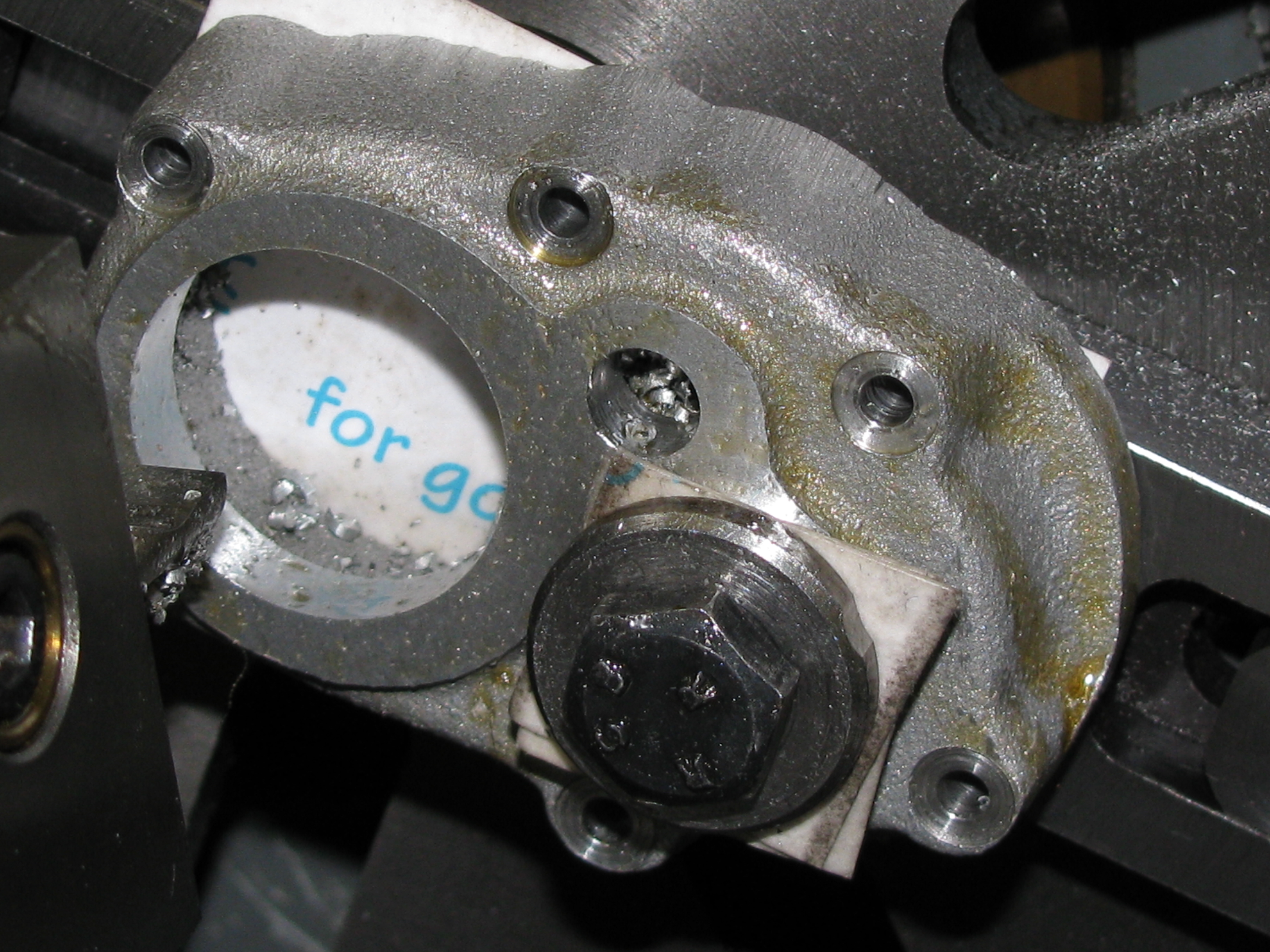
Mounting this casting for boring out the big hole for the ignition timing cover was a bit of a poser. I could not find a satisfactory way of setting it up in the 4-jaw chuck. I hate using clamping dogs on the faceplate. I needed a way to clamp it to the faceplate by the crankshaft hole, but this has to be positioned too close to the axis to use one of the faceplate slots, and I am not having an Emmental faceplate. The solution was to make a general purpose accessory for the faceplate in the form of a bar with a tapped hole near the middle, and recessed slots for special bolts near the ends, so that any radial offset can be achieved, up to that available from the standard faceplate slots. The bar was finish turned in-situ, to ensure a true face.
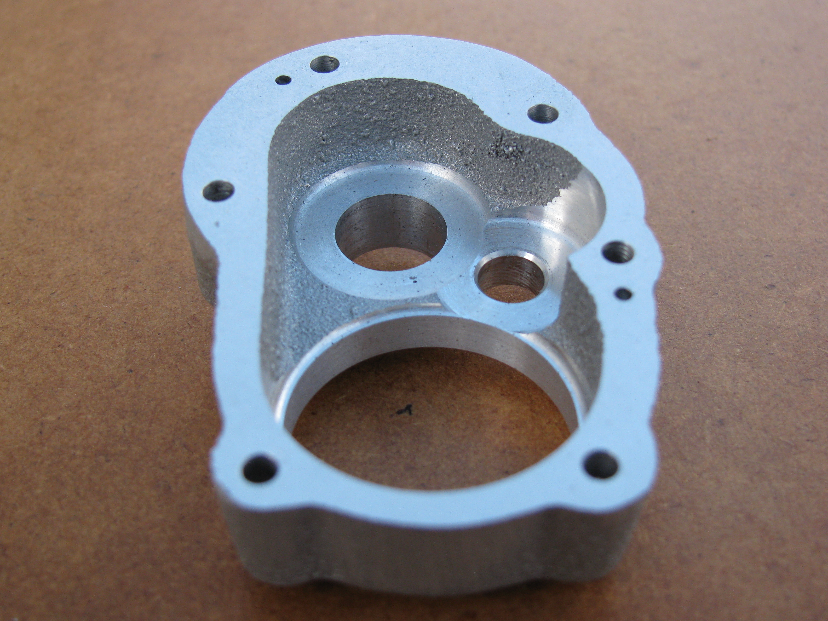
In this case the hole is much bigger than the original design. In order to keep the ignition timing arrangements as compact as possible I am not using an effectively separate chamber. The timing case has to accommodate the ring carrying the magnets for the hall-effect sensor, and these need to be mounted at quite a large radius to give the correct dwell. As expected, boring this hole left a very narrow face near the top of the casting, but it is just about OK and will have to do.
With the casting turned over, each of the holes was set running true in turn so that the interior could be bored out to provide clearance for the gears. I used a tool with a generous radius for this. The depth is intended to allow 0.005″ end float for the idler pinion. (2½ hours)
2011-12-10 - Dressing
I started work on cleaning up the cast surfaces, as the two were done as an assembly, covers the work on the Timing-End Bearing Housing. Today I worked about half way round the periphery of the pair. (3 hours)
2011-12-21 - More dressing
I did some more dressing work today, and although there is more to be done, thought I should do a trial assembly to make sure everything is OK. (1 hour)
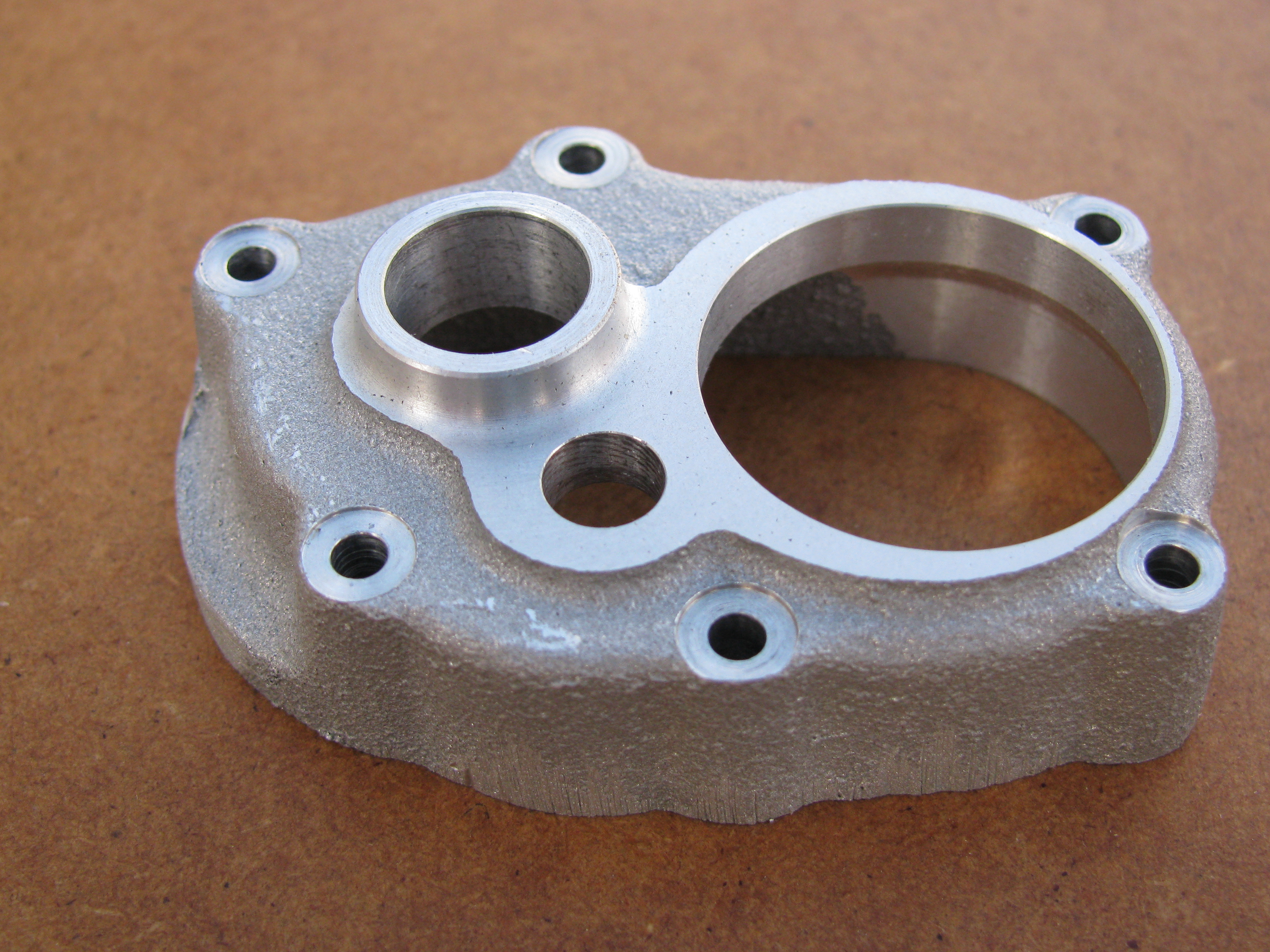
2011-12-31 - Re-profiling boss
Satisfied with the trial assembly, I got back to work on cleaning up. I made a plug for the large hole, with a 0.04″ land on the shoulder. Using a diamond point in the Dremel, rifflers, files and wet-or-dry paper, I cut the machined boss surface back to the plug. I did some more work on shaping the lower sides. I found an MDF block for mounting the assembly for sand-blasting, and started work on the remaining plugs. (2½ hours)
2012-01-01 - Oven-ready
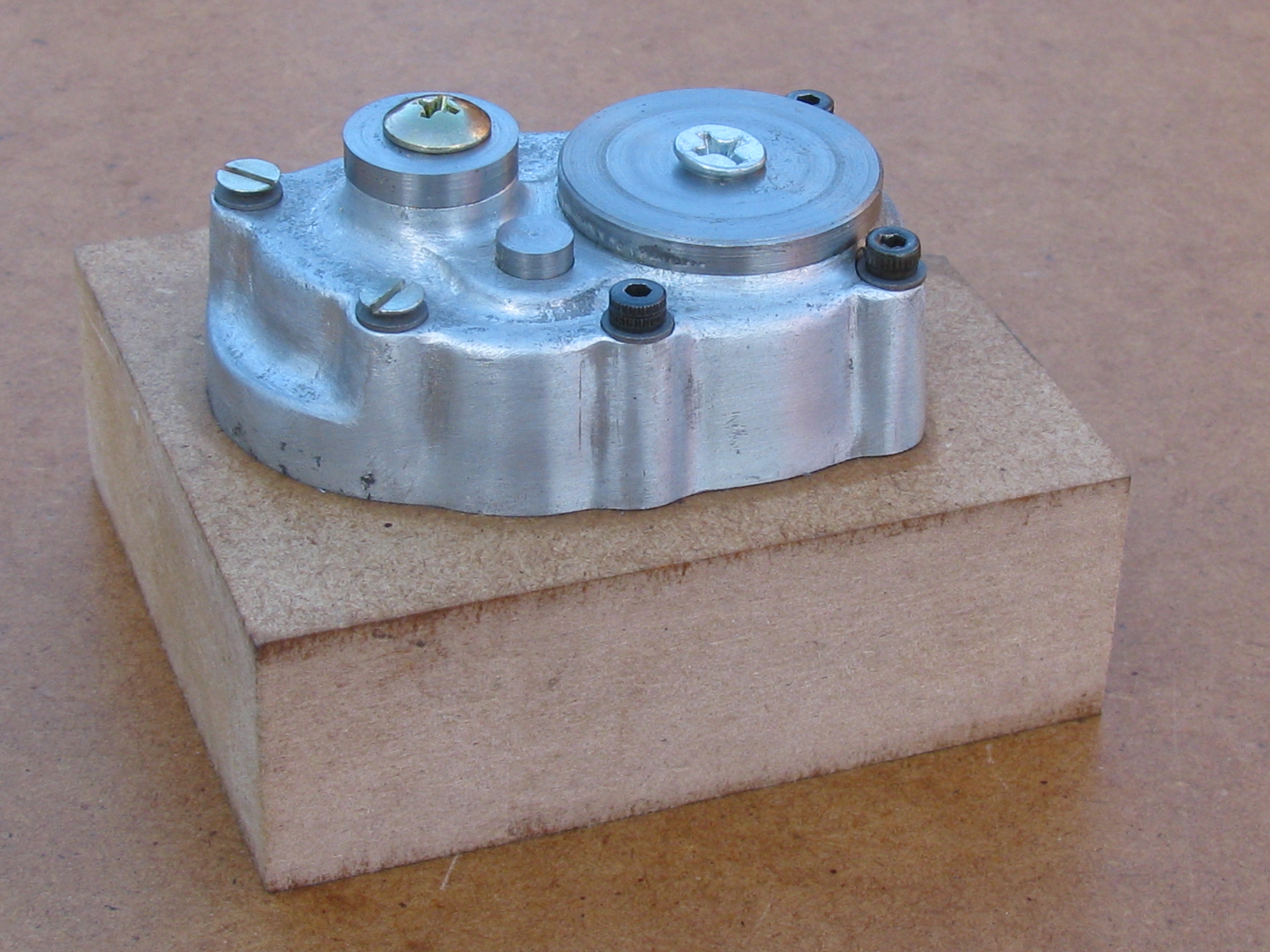
I finished the fettling work on the timing case castings, blending in round the hole for the idler stud, and the crankshaft boss, as I want all this to appear to be part of the cast surface. It is hard to know when to stop. I bored out the MDF block to accommodate the spigot on the back of the Bearing Housing, and machined the two remaining plugs. With suitable screws found, and all the joint faces greased for protection, the castings were trussed-up ready for sand-blasting. (1¾ hours)
2012-01-04 - Blasting
After taking a trip to a local works for sand-blasting, I dismantled the assemblage and cleaned the parts in paraffin and then hot water as usual. I found the idler hole plug did not want to come out initially. I had to file it a little to get it out cleanly, though I am not sure why. (about 1 hour)
.
Conclusions
In machining two of these castings it turns out that a combination of the skimpy design allowances and an inaccurate casting mean that it is pretty much impossible to get a really satisfactory result even with modifications. ETW generally has not allowed sufficient metal for a proper seating for the 6 BA nuts. This is exacerbated by the pattern having excessive draw on the bolting lugs, and the boss faces being poorly positioned in relation to the periphery. While there is room for improvement that would make life much easier, I would not go so far as to say that the casting is not good enough. Clearly, I and many other makers before me, have managed to make a successful job of it. It is tricky, but it just needs care and planning. This casting has as much detail, and does as much to define the visual character of the engine as any, so it is important to get the best out of it.