
Sump
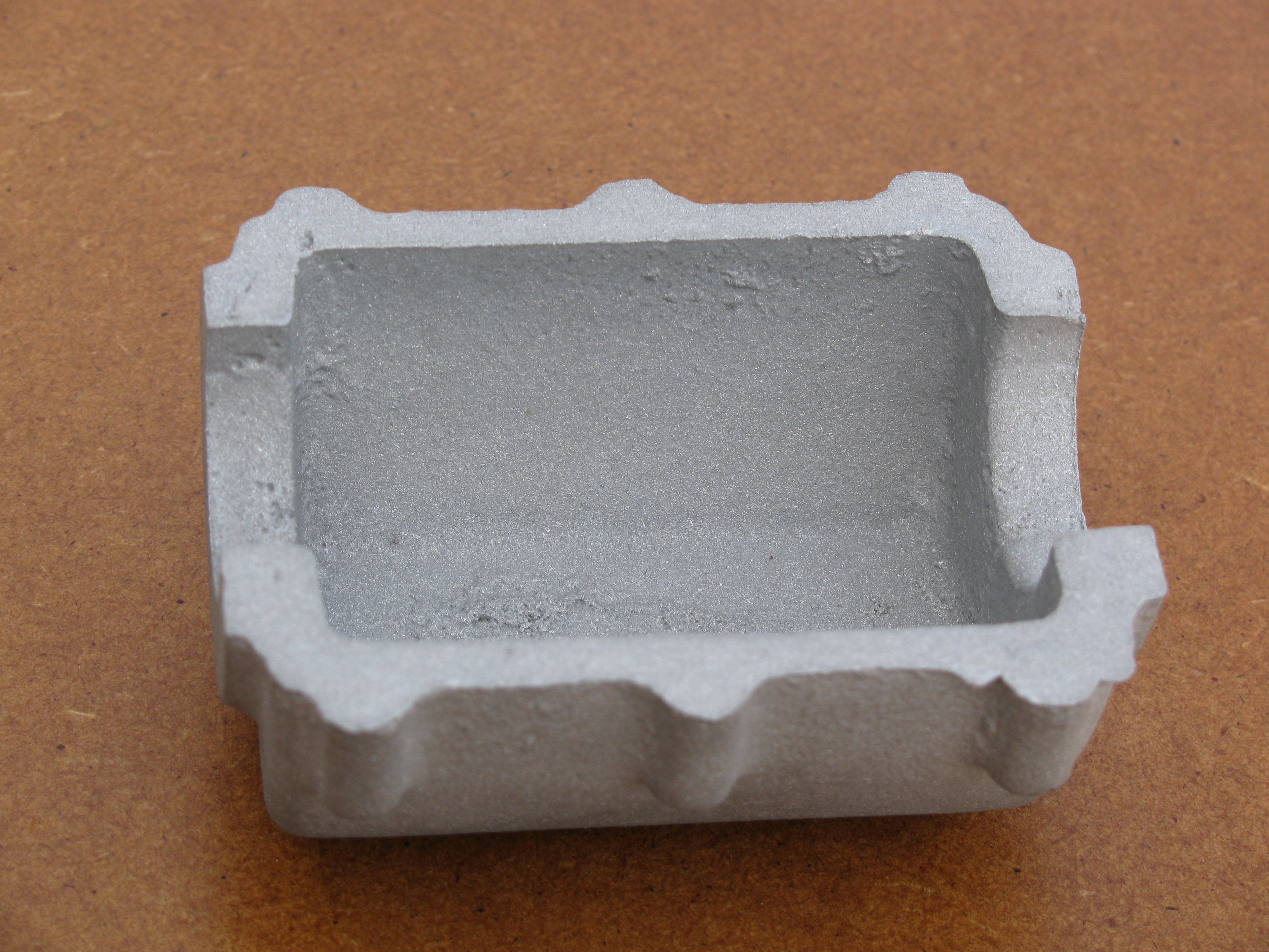
The casting arrived from Hemingway on 27 March 2010. It is a nice little casting which does not appear to present any problems. The wall thickness at the rim is gratifyingly generous. Pleasingly also, there is a boss for a sump drain plug. The draw on the bolting bosses means they are a bit wide at the face and may want a bit of trimming to give more room for the engine bearers area.
For locating accurately on the crankcase, dowels may be a good idea, but there is not much room for them, They could either be tubes round a couple of the bolts, or perhaps better, pins at the ends. Spotfaces will be needed on the inside for the oil trough pillars.
As it turns out, these bosses are not positioned with brilliant accuracy and quite a bit of jiggling about was needed to optimise the compromise.
2010-03-28 - First hole
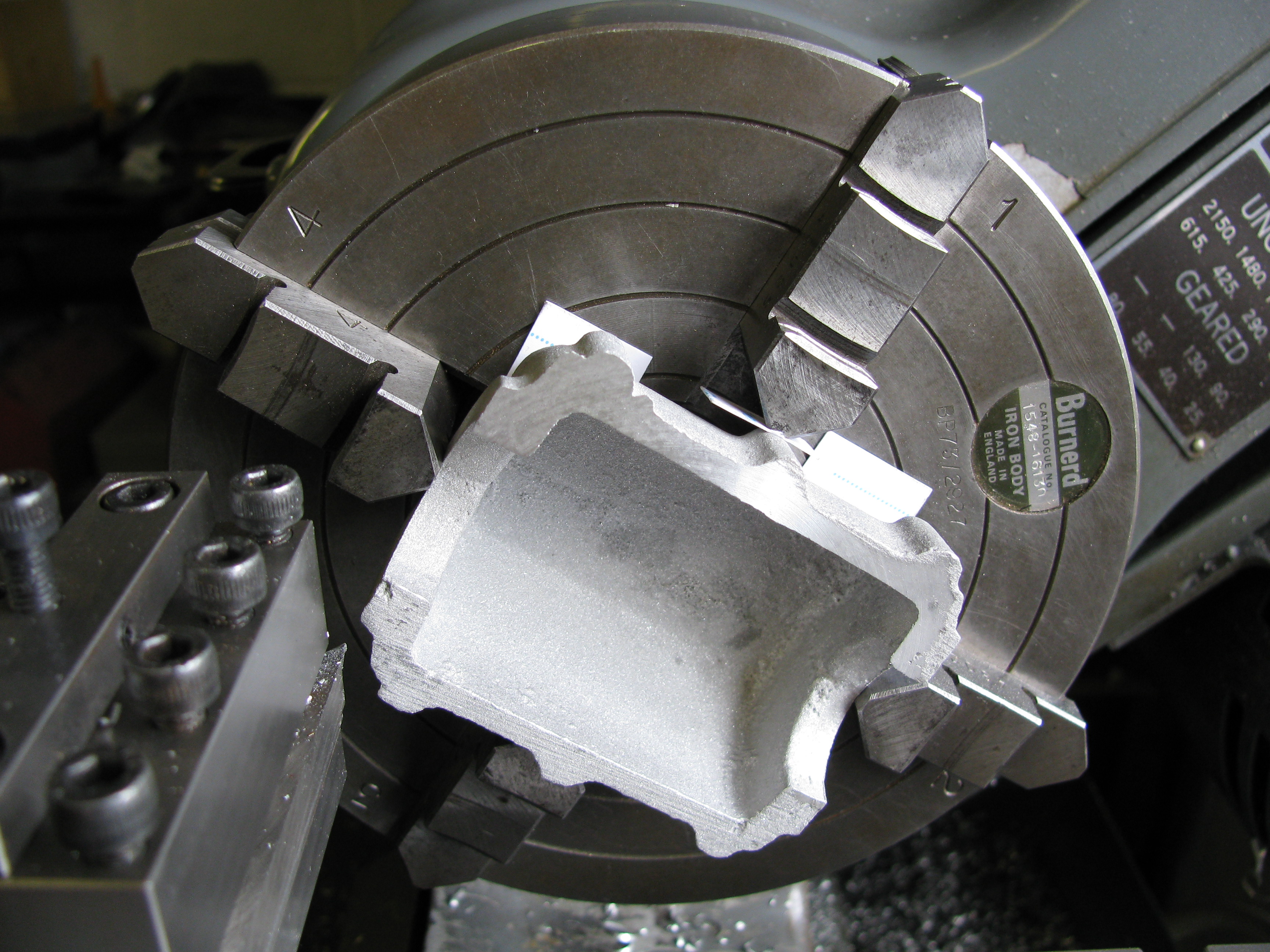
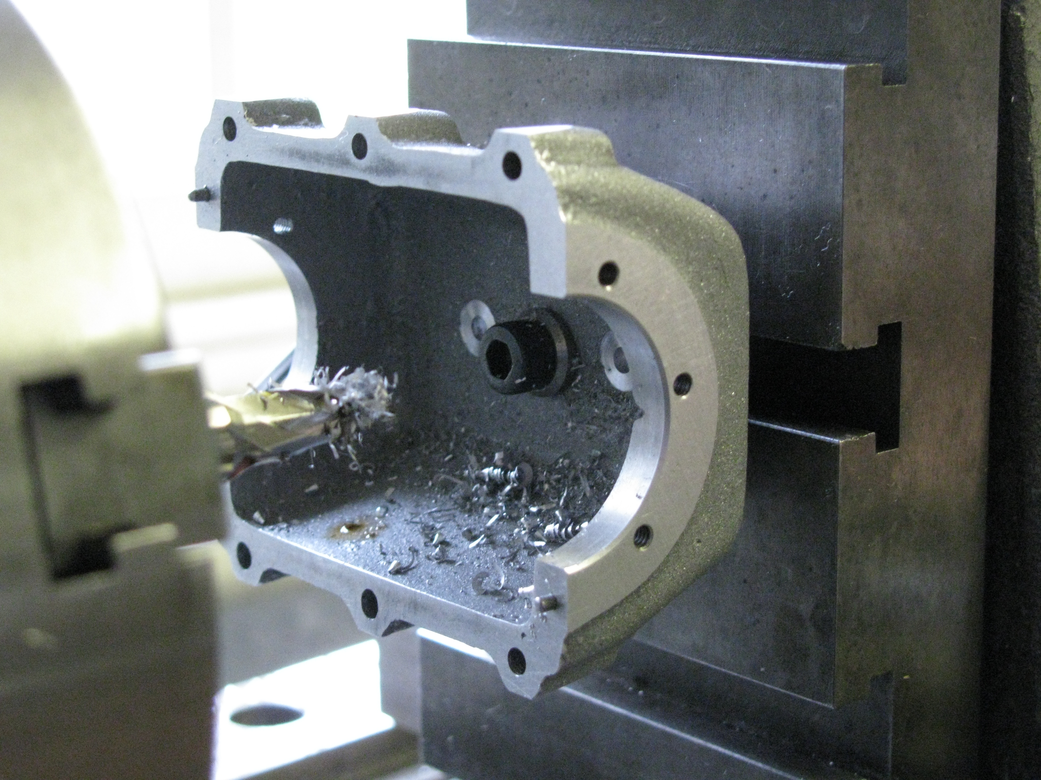
I set the casting face out in the 4-jaw, packed with card behind and on the bolt lugs, and took several cuts of about 20 thou, cutting dry, and one of 2 thou to finish, with Rocol RTD on the face. The outside height is 11⁄8″ at the greatest, while the inside measures up to 1⁄64″ too deep, indicating that the floor of the casting is a shade thin.
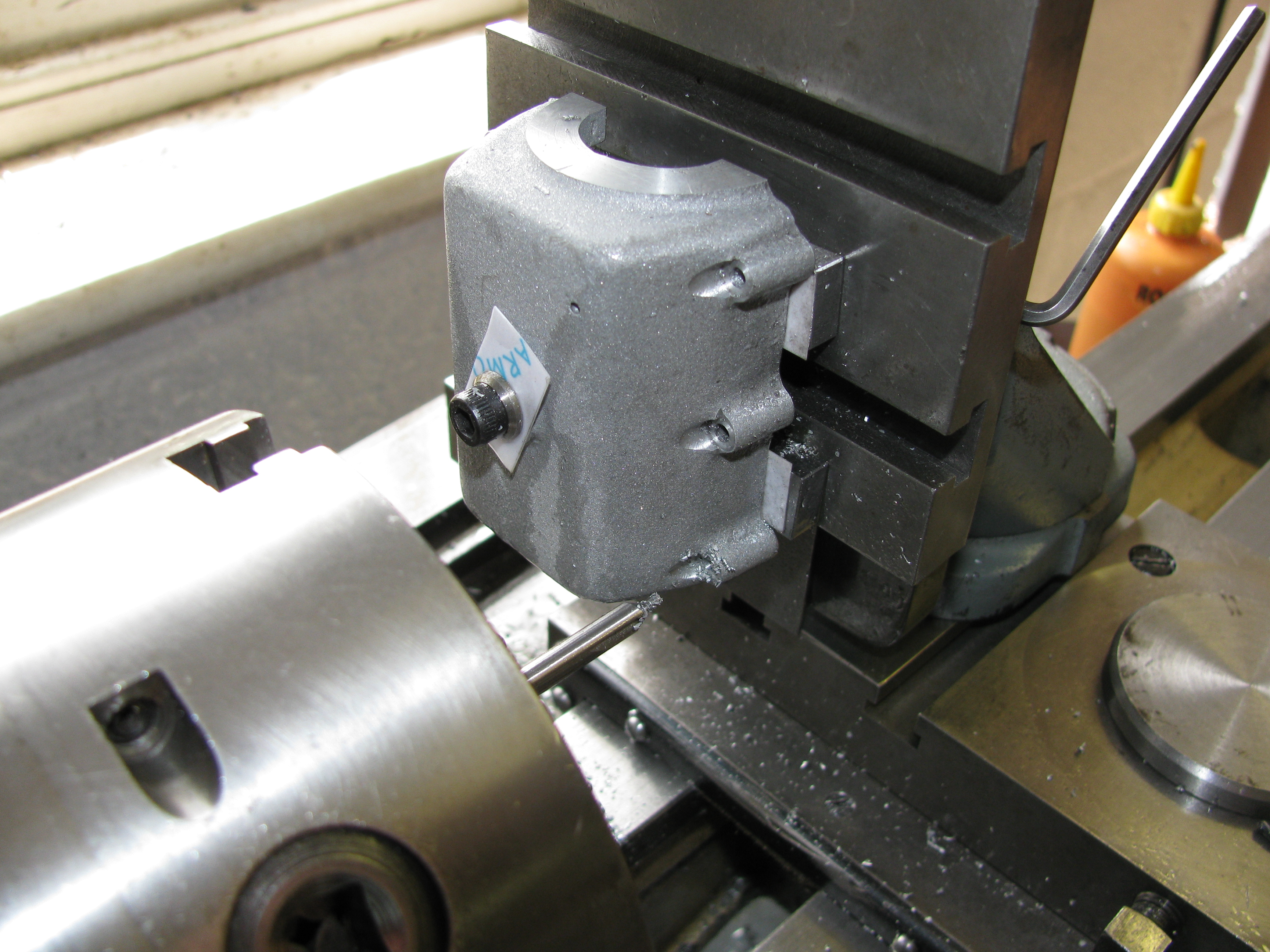
I turned over and set the drain boss running true. This was faced off to 1⁄16″ proud, centred, drilled 5 mm & 5.3 mm, and tapped ¼″ x 32 tpi. A good clean thread resulted, giving confidence for future work.

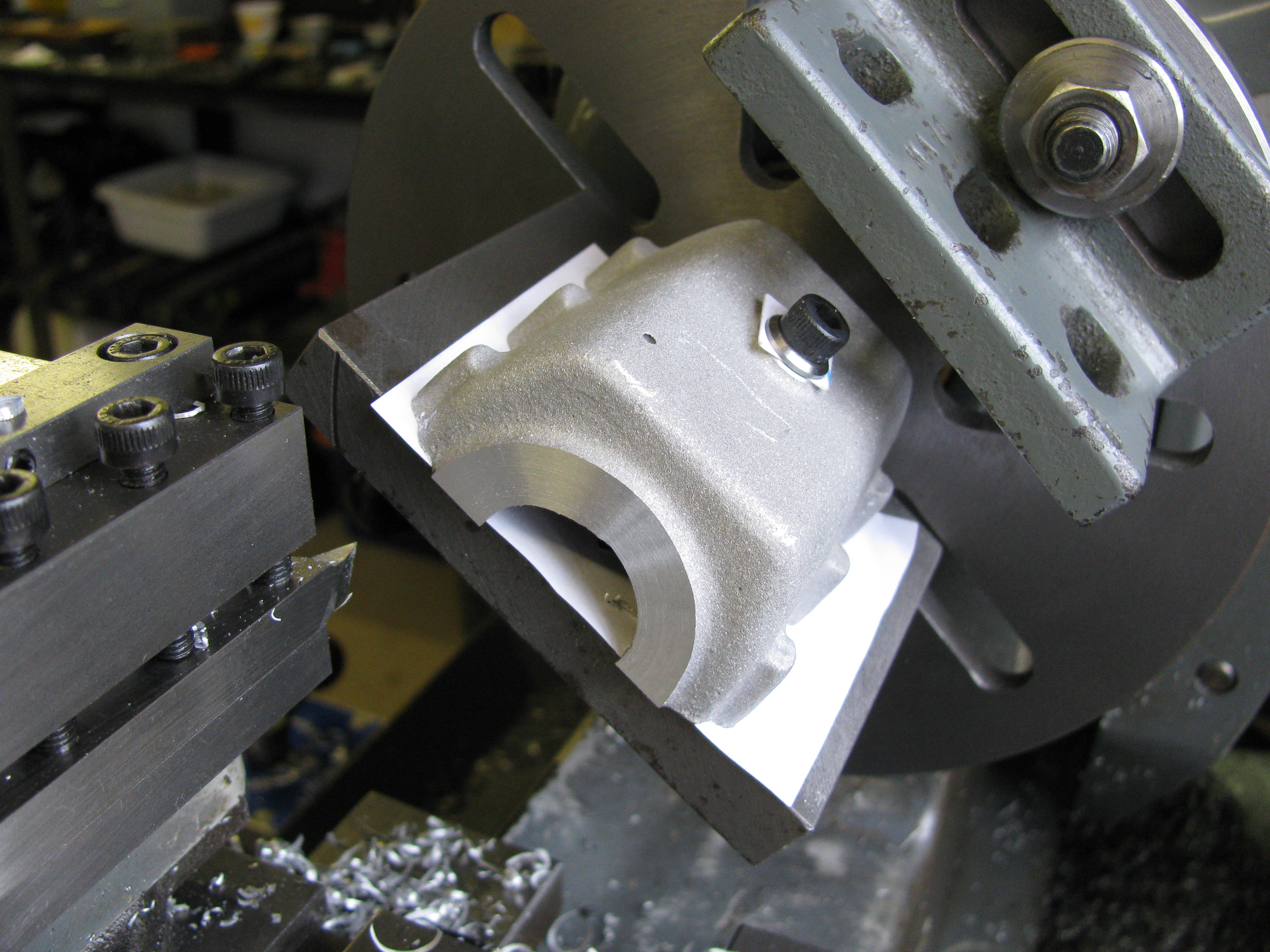
Using this hole, I clamped the casting to the angle-plate, squared up by the cast outside side surfaces and took about 30 thou off one end face. I do not normally like set-ups with a single bolt, especially when, as here, you have to be careful to avoid over-tightening and distorting the work; but the rim of this casting is plenty broad enough to be sure the job would not shift. I then turned it round and set the machined surface against parallel packers (removed before switching on) to do the other end. (2½ hours)
Preliminary measuring up shows that the bolting lugs are out of position by perhaps as much as 1⁄32″. This presents a dilemma - work to drawing or work to casting. The difficulty lies not at the rim, there is plenty of metal there, but at the bolt head seating counterbore. If the bolt heads are to have a full seating area, there is very little latitude for disagreement. On the other hand, working to a random layout presents several pitfalls. A more careful measurement, estimating the centre of each lug by eye, shows a range of 0.035″. In relation to other features of the casting, the worst is about 27 thou off position, but a bit of juggling could bring that down to half the range. This would result in one end wall being 20 thou thicker than the other, and a considerable difference between the amount of bearing housing boss left standing above the cast surface, 1⁄32″ one end and 1⁄16″ the other. Drawing this out shows that the mislocation of the lugs will still be obvious.
2010-04-10 - Lug-holes
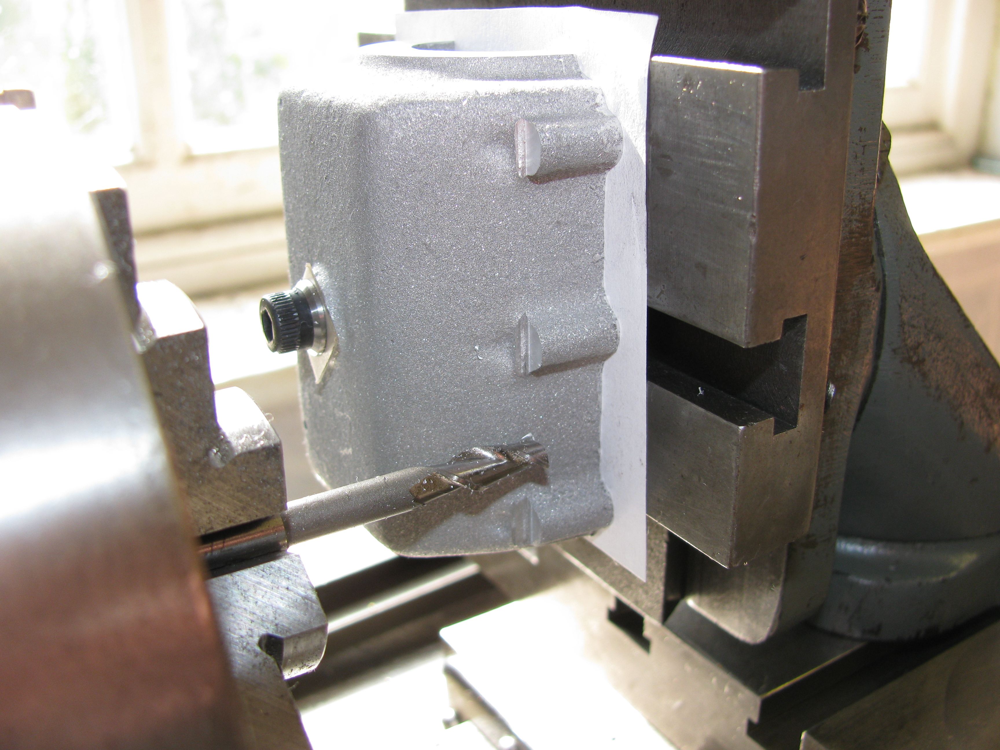
I thought it might help to decide the lug position problem if I took a proving cut over the outer bit of the bolt seatings to give a more accurate indication of the available metal. This cut again showed the greatest discrepancy to be about 35 thou. On one side the lugs seemed to be tilted a bit. Chewing the job over in the meantime had come to the conclusion that working to drawing would be best if possible, and it seemed it would be. If it turns out that the lugs were too obviously out of position, there is enough metal to re-profile them. I don't think it will be necessary, as this engine is not intended to be a glam job, and the sump will be mostly hidden by the engine bearers anyway. The best compromise position will require 35 thou taken from the 'blow-hole' end, and 75 at the other.
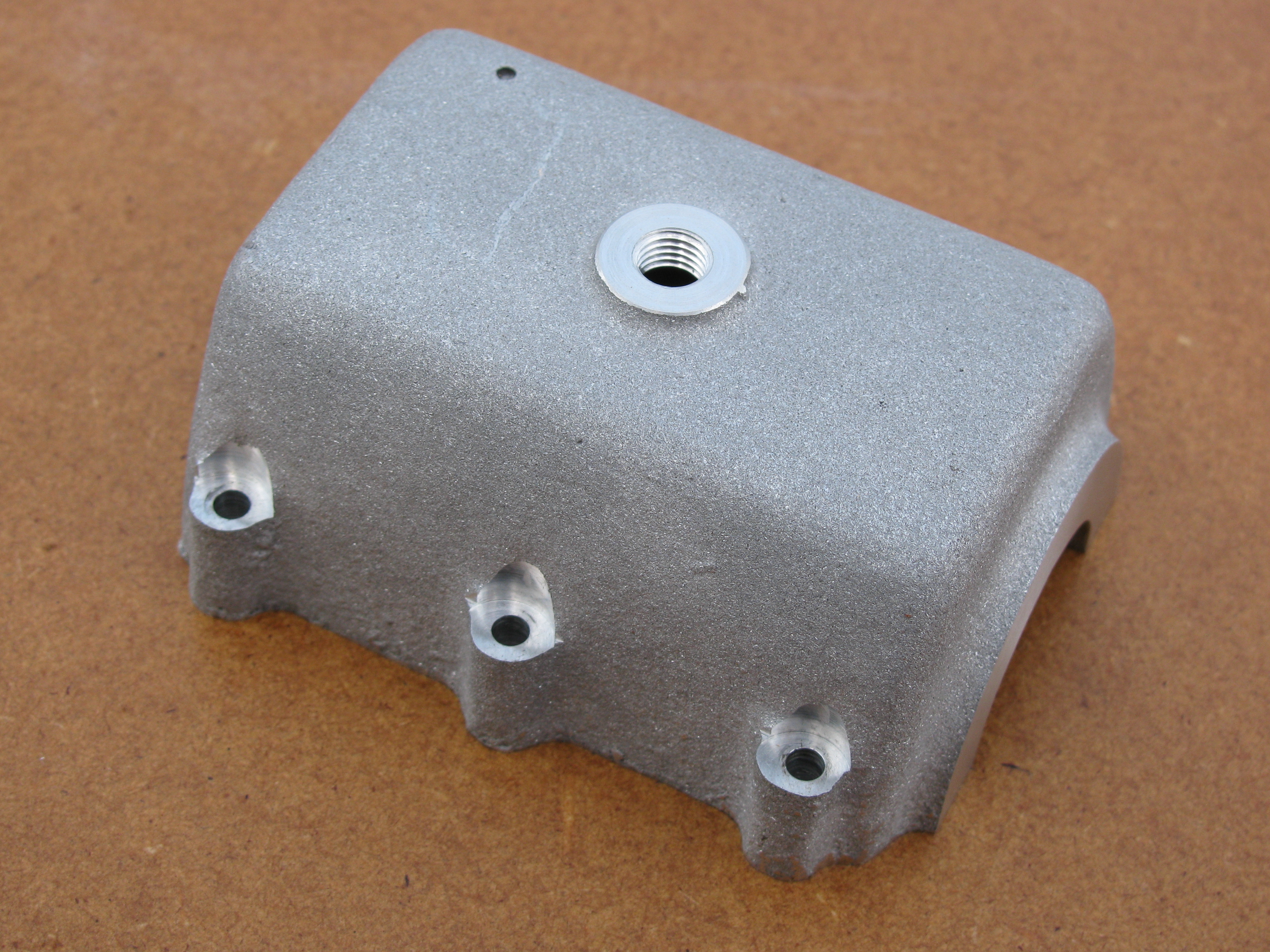
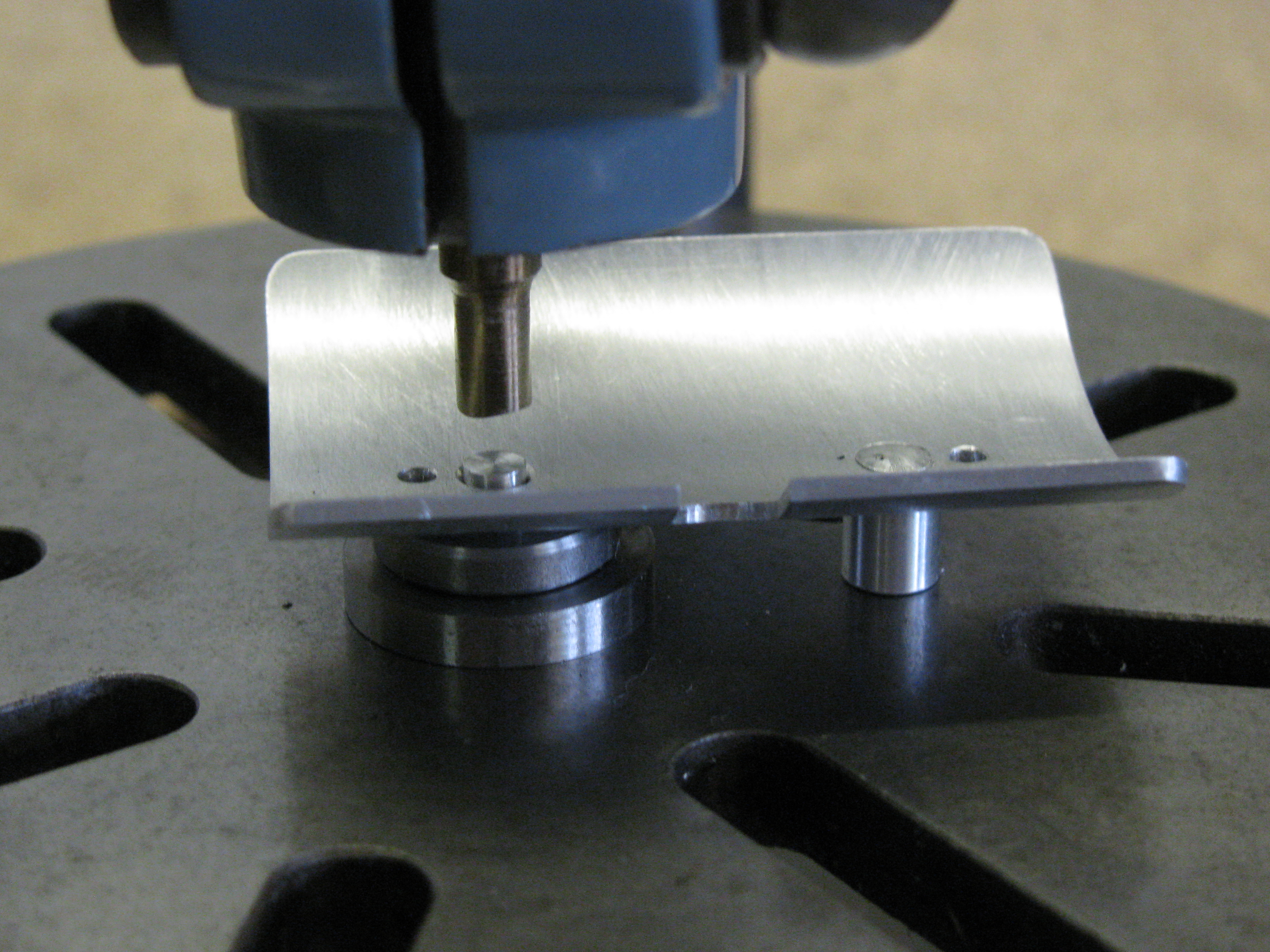
Having finally decided a plan, I set the sump up on the vertical slide again with the machined end surface clocked level and packed out to allow through drilling. I used the cross-slide dial to find a centre from the sides, between the lugs. I first took a set of plunge cuts with a 7⁄32″ long series slot drill to make the pockets, using the dials for measurement, and then went round the six lugs a second time centre drilling, pre-drilling 2.7 mm and finishing 2.9 mm each one. Finally, with a 5⁄16″ slot drill, offset outwards by 45 thou from the centreline of the hole, so as not to cut any deeper into the wall of the sump, I finished the pockets to depth. This cleaned away most of the remaining knobbles of unwanted lug at the sides of each pocket. Now back to the crankcase. (3½ hours)
.
2010-04-14 - Dowel holes - part 1
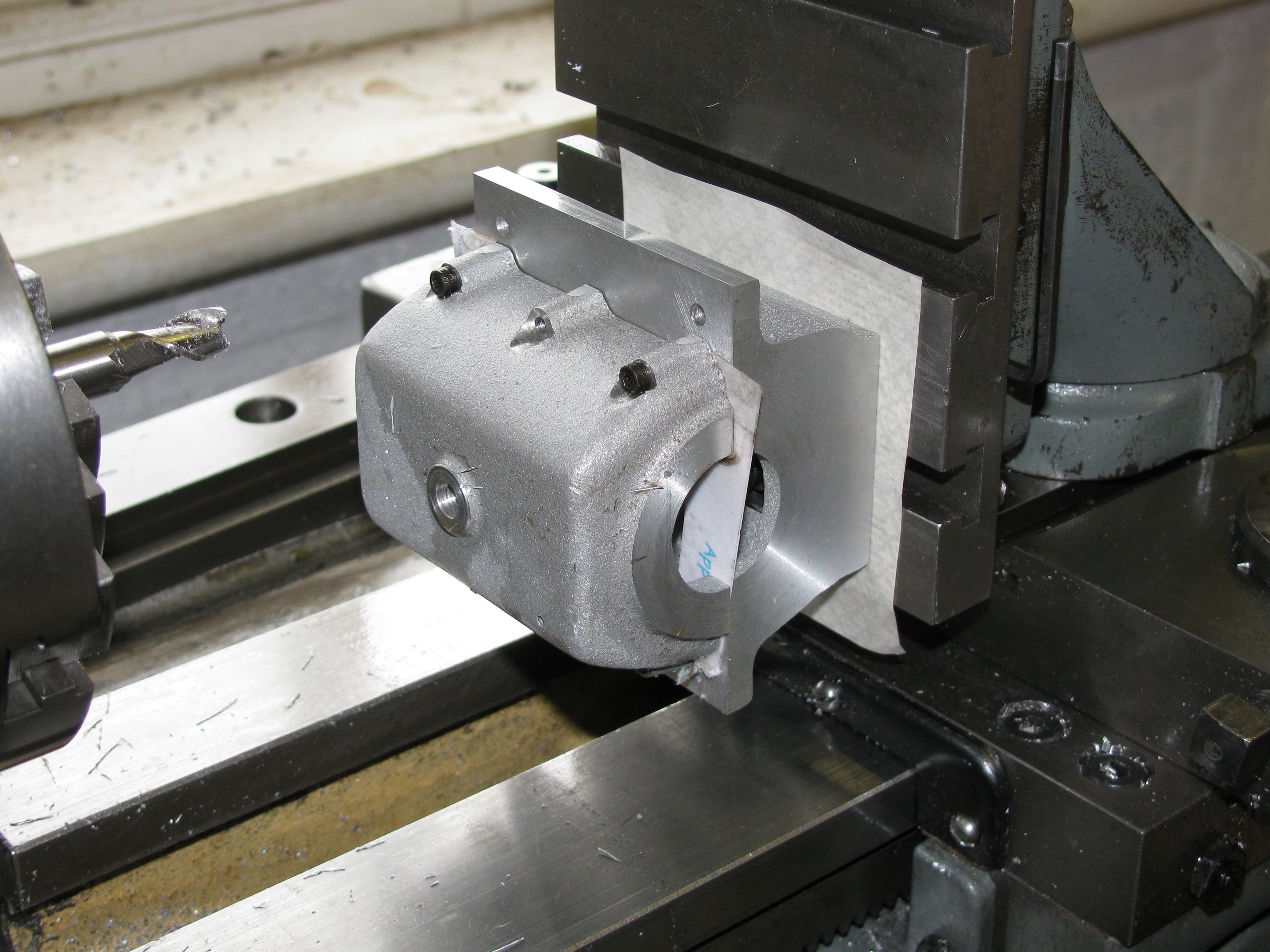
I wasted quite a bit of time in trying to work out the best way to set the sump up for drilling dowel holes. The problem is that the six fixing holes provide the only datums for working out the positions of the dowels. After faffing about trying to get some reliable measurements, I decided to set the sump and crankcase up together and take a cut over the sides of the lugs, which need reducing anyway to allow an adequate width for engine bearers. I machined it to 217⁄64″ overall. (2 hours)
2010-04-15 - Dowel holes - part 2
After yet more fruitless tinkering with measuring the hole positions, I again temporarily fixed the crankcase to the sump to set it square on the vertical slide. The dowel holes were then drilled by measurement on the slide dials. The result was dowels that do fit quite nicely, but with the sump 6 thou out of square. The randomness of my hole drilling on this sump is a bit of a worry. I will have to improve my methods before getting to some of the more critical items. The precise location offered by the dowels is such an advantage that I will use them, despite the slight positional error. It is the end faces and bores that matter most. Some of the fixing lug holes will now have to be opened out to fit. (5½ hours)
2010-08-01 - Boring and facing
The seatings at each end for the bearing housings were machined with the crankcase and sump bolted together for accuracy. This covered in the Crankcase section.
2010-08-09 - Sump plug and boring
Wanting a diversionary job today I made a steel sump plug and a copper washer. A bit of brass was machined in situ as a second operation chucking piece. As I have done before, I used a piece sawn off an allen key to broach the 1⁄8″ hexagonal hole. I need to make a proper broach sometime. The washer, parted from a length of thick walled pipe, still needs to be annealed. (2½ hours)
Oil Trough
2011-07-19 - Rolling the Oil Trough
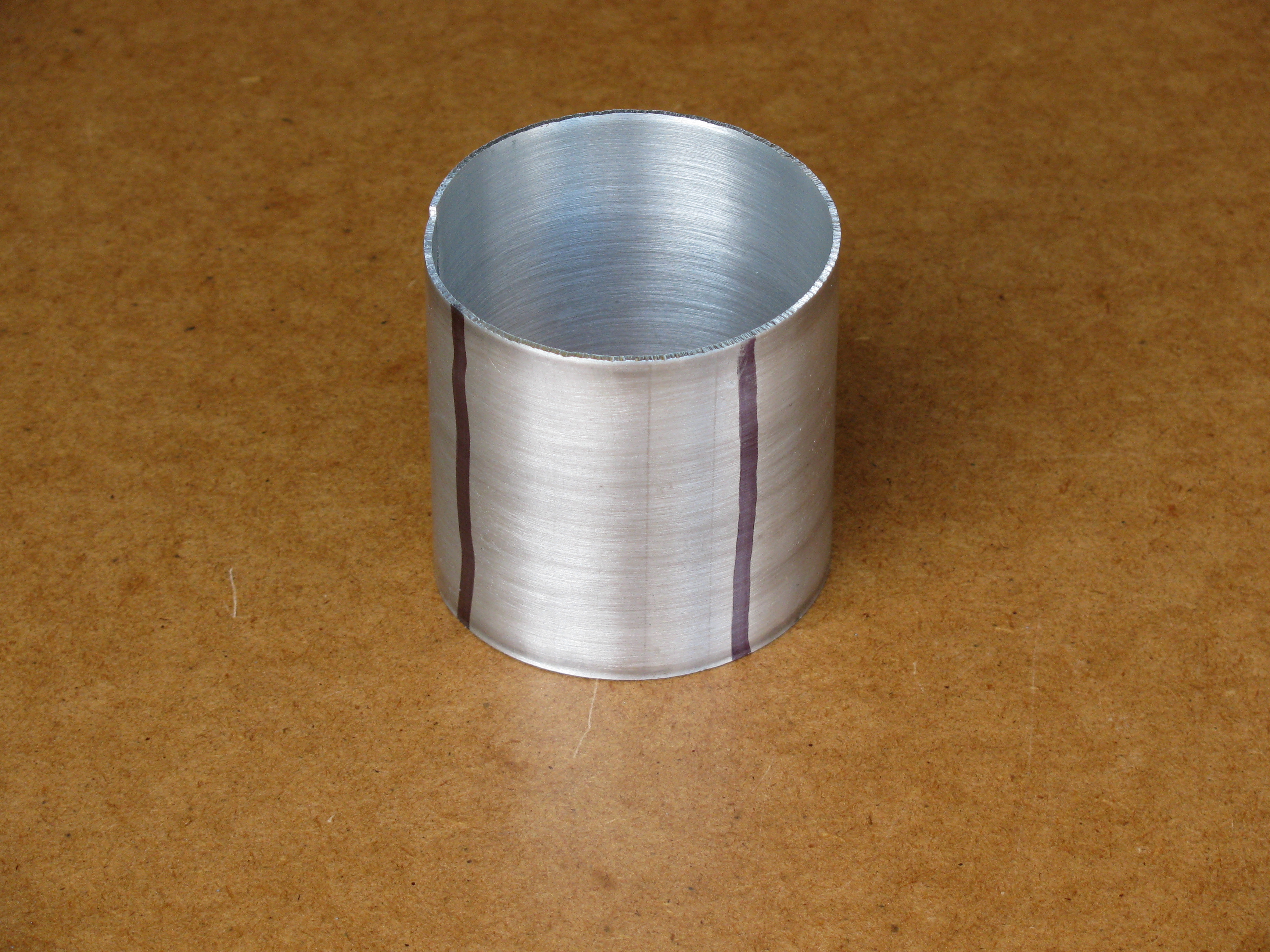
I was about to start work on the oil trough when it occurred to me to check the big-end clearance. Laying the con-rod out at various positions it soon became clear that it was a useful thought. The clearance was much less than none. After a bit of trial and error in the CAD drawing I decided on outside radius of 11⁄8″ instead of the ¾″ inside radius of the original, and an offset of 1⁄32″ to the oil filler side, which made a surprisingly large difference in allowing for the asymmetry of the big-end motion due to the désaxé cylinders.
I cut out a rectangle of aluminium sheet and squared it up. I rolled it, with my recently constructed bending rolls, to a full circle, 2¼″ diameter, and cut out a piece for the trough. It just fit endways in the Myford vice with a steel strip substituted for the moving jaw. In this position I drilled the oil holes, drilled and spot-faced the seats for the posts, and milled the dipstick clearance slot. I made countersinks on the concave side by hand, for riveting the posts into. (2 hours)
2011-07-20 - Posts, profiling and drilling the sump

First I made up the oil trough posts from some alloy bar left over from another job, as simple turning job. Next I made an alloy block to clamp in the machine vice. I drilled and tapped the mounting holes in situ, providing a centre-line datum for profiling the trough. I milled the profile all round, and after cleaning-up, filed the corner radii.
With the vertical slide already in place, I set the sump up to work on the trough mounting holes from the inside. Working from the semi-circular bearing-housing bores, and remembering the 1⁄32″ offset, I drilled and spot-face the holes, working from the leadscrew handwheel for depth, but remembering at the last minute to check with the depth micrometer. One was spot-on and the other 0.002″ high, which is fine. Re-mounting the other way round, I found the d-bit countersink I had made to suit the screw-head diameter would not cut, so I had to use an ordinary one instead. (5½ hours)
2011-07-21 - Riveting
To rivet over the ends of the post I could have used a rivet snap, but the concave depression in the end is not easy to make. I milled a concave curve across the end of a piece of silver-steel with a ½″ slot drill and used this by rotating it between light hammer blows to swage a domed head on the posts. I did not bother to harden the punch for forming just two heads in aluminium. I also made a hollow support for the post, and a spacer to allow the second post to be fitted. Using the Pillar Tool, this procedure worked effectively, but the heads are not perfect.
The finished oil trough fitted nicely in the sump, but was a bit close to some of the internal corners. This was a question of the interior cast shape of the sump, and it was soon remedied by using a spherical burr in the Dremel to clean out a couple of the corners. (2½ hours)
2011-07-22 - Screws
I made a simple 6BA stud box to allow the two ½″ long contersunk 6BA screws to be parted-off cleanly to 9⁄32″ long. I found the backing screw, used to set the depth, needed a locknut to prevent a, er, screw-up. A couple more screws were cut for fixing the timing plate to the crankcase, with the only difficulty being to find the one that flew off behind the lathe stand. (1½ hours)
.
2011-11-22 - Idler Stud
The next job was to make the cut-away for the idler stud. This passes through the Timing Case and Bearing Housing, and a clearance hole is needed for the nut, lying on the joint between the Crankcase and Sump. This is described in the Timing-End Bearing Housing section.
2011-12-02 - Dressing the cast surfaces

The flats milled on the bolting lugs need to be blended in and the whole surface gone over to remove rough lumps in preparation for sand blasting. I made a couple of mild steel filing buttons to get the right profile on the lugs. the top one is smaller than the bottom, so that it retains an apparent casting draw. Today I worked over most of the general surface and more-or-less finished one lug. I think the bottom button needs to be a little smaller, not too small, or the mating surface will be too narrow. I think reducing from 0.300 ″ to 9⁄32″ would be about right. (1¾ hours)
2011-12-07 - More hand work
I made a new 9⁄32″ bottom filing button and made the top one (0.225″ diameter) much shorter to give better access. I finished filing and paper rubbing one side, ready for sand blasting. This is quite fiddly work and I did most of it wearing a headband magnifier. I find the best tool for a lot of the work is a round riffler (Grobet). This gives far more delicate control that trying to wield a Dremel. (3¼ hours)
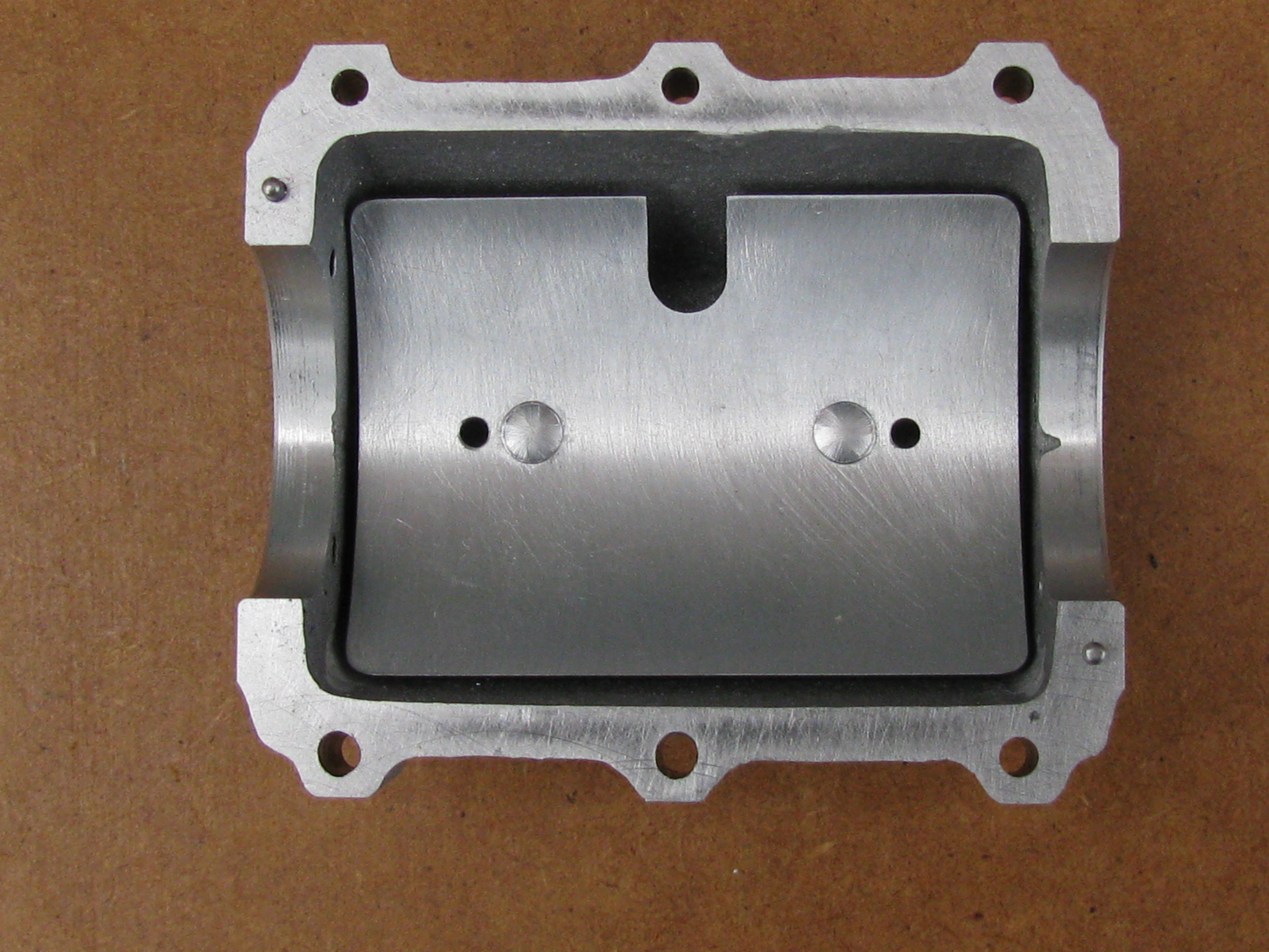
2011-12-09 - Blasting
Sunshine this morning allowed me to catch up with some photos. To get a reasonable depth of field on these macro images requires plenty of light to allow the camera to stop down.
Then I finished dressing the second side of the casting, and started making bits and pieces to protect the machined surfaces for blasting. I made a plug for the drain hole and turned down the heads of some fine wood screws to plug the lugs but allow the blast to get at the pockets. I cut an MDF plate to the exact length of the casting and made covers for the ends, held by a stud through the length. I put a smear of grease on the machined faces of the casting, in the hope that it would help prevent the sand getting under the edges.
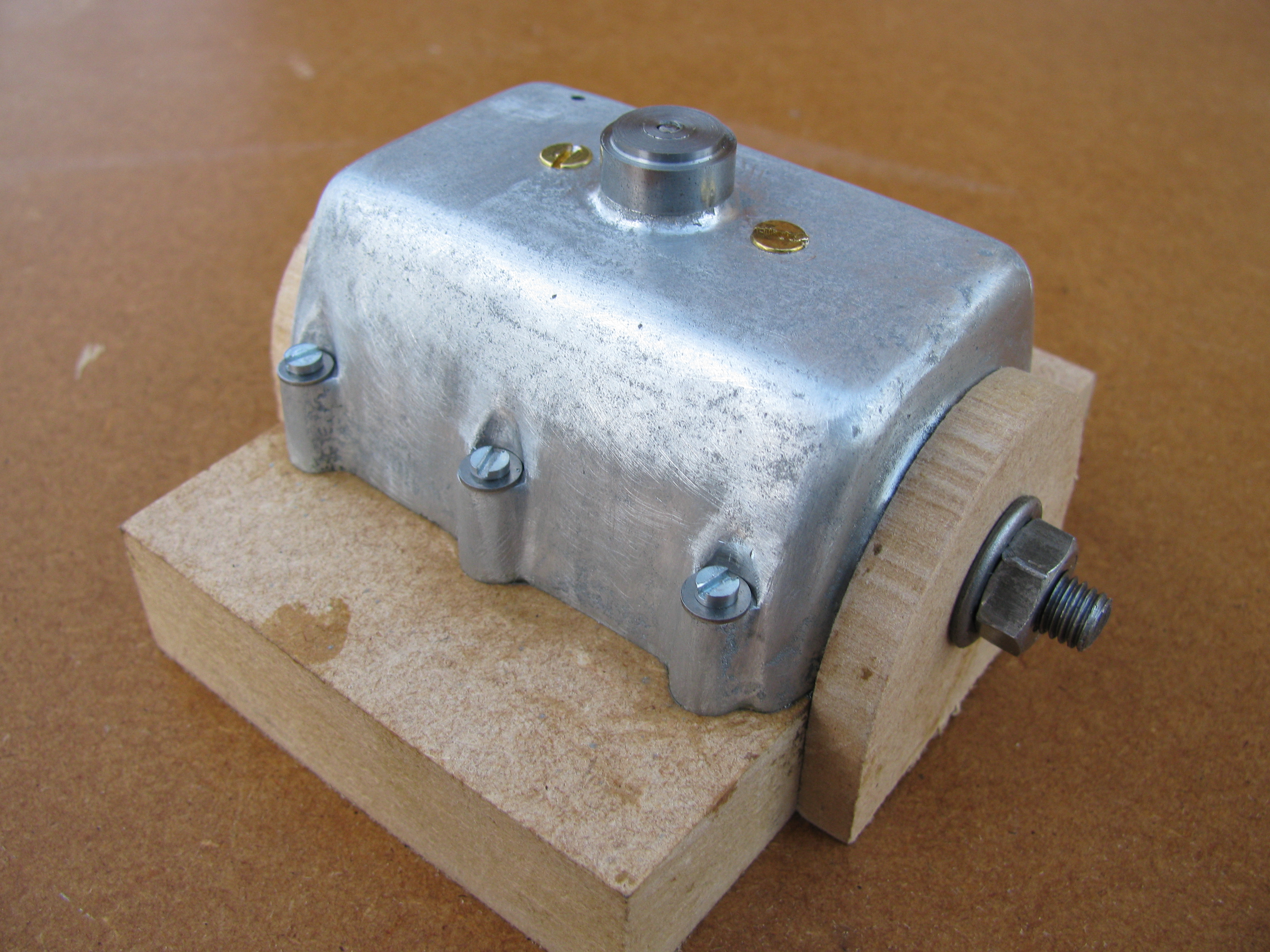
After a trip with the trussed-up casting to a nearby shop with a sand blast cabinet, and a blow over with the air line, I took all the gubbins off and treated the casting to a wash in paraffin and a scrub in hot water and detergent. There is a quite noticeable cavity in the surface, but I did not bother about it greatly. It is not deep and will not be visible when the engine is finished. (3¼ hours)

2014-04-22 - Sump Nuts started
Yesterday I drew up an extended sump nut having the hexagon standing above a cylindrical portion that contains the thread. Needing a break from the fine filing work on dressing the cylinder castings, I made two nuts and started a third. (1½ hours)
2014-04-26 - Sump Nuts completed
First job today was to finish making the set of sump nuts, including a spare. Now back to No 2 Cylinder Cover. (1¼ hours)
.