
Drive Coupling
This is not part of the Westbury design or the Hemingway kit. I made it at this stage because I wanted to be able to turn the engine for running in or lapping the timing gears.
2011-09-17 - Doughnut cutters
I made some cutters for the rubber ring "doughnut". These are made from mild steel bar machined to form a thin-walled tube with a shallow taper at the business end to form a sharp cutting edge. The cutter is rotated at moderate speed and fed into the rubber sheet. I cut one trial piece. The bore came out nicely, but the OD was tapered from about 10 thou to 30 thou undersize. (1¼ hours)
2011-10-16 - Drive pins, bushes and washers, and more doughnut cutting
Today I turned the six washers and shouldered bushes that will fit in the rubber ring and parted the drive pins from 6-BA hexagon rod and got my 5-BA die set up in the tailstock die-holder to cut the threads to the right size.
I also had a couple more trials with the outside doughnut cutter, reducing the wall thickness to just 0.008″ and trying different lubricants. Paraffin (kerosene) is better than washing-up liquid but the results are still tapered and too small. I do not have a lot more of the rubber sheet sample to play with. I seem to remember that rubber can be ground.(4¾ hours)
2011-10-18 - Thinking time
Today was mostly spent playing with ideas, trying to work out just how to make this ruddy doughnut. I do not want to invest a lot of time in making jigs. On the other hand it has got to be pretty accurate or the drive shaft will not run true. At this point I do not have a clue how to accurately position the six holes.
To get at least something done, I also spent a bit of time on the drive pins. (2½ hours)
2011-10-29 - Another try at the doughnut cutter
I made a last attempt at using the annular cutter by making some notches in the cutting edge to make it a bit like a crude hole-saw. The resulting ring was more parallel, but the surface was too rough and had a lot of rubber crumb embedded in it.
Needing more time to ponder the doughnut, I made a start on the drive flange instead, completing the first operation turning of the rim and hub. (1½ hours)
2011-10-30 - Drive flange
With the flange turned round in the chuck and clocked up, I faced it to length, bored it and cut the chamfers. Using the dividing head on the saddle I drilled and tapped the 5BA holes for the drive pins, and then back on the spindle, all without disturbing the job in the chuck, for slotting the keyway. I reversed it again, gripping the flange in soft jaws to chamfer the bore for shoulder radius on the drive shaft, and taking a minimum shave off the face to remove the burr from cutting the keyway. The keyway turned out not to be deep enough, so I sharpened the slotting tool and re-worked it from the boss end. (3 hours)
2011-10-31 - Doughnut at last
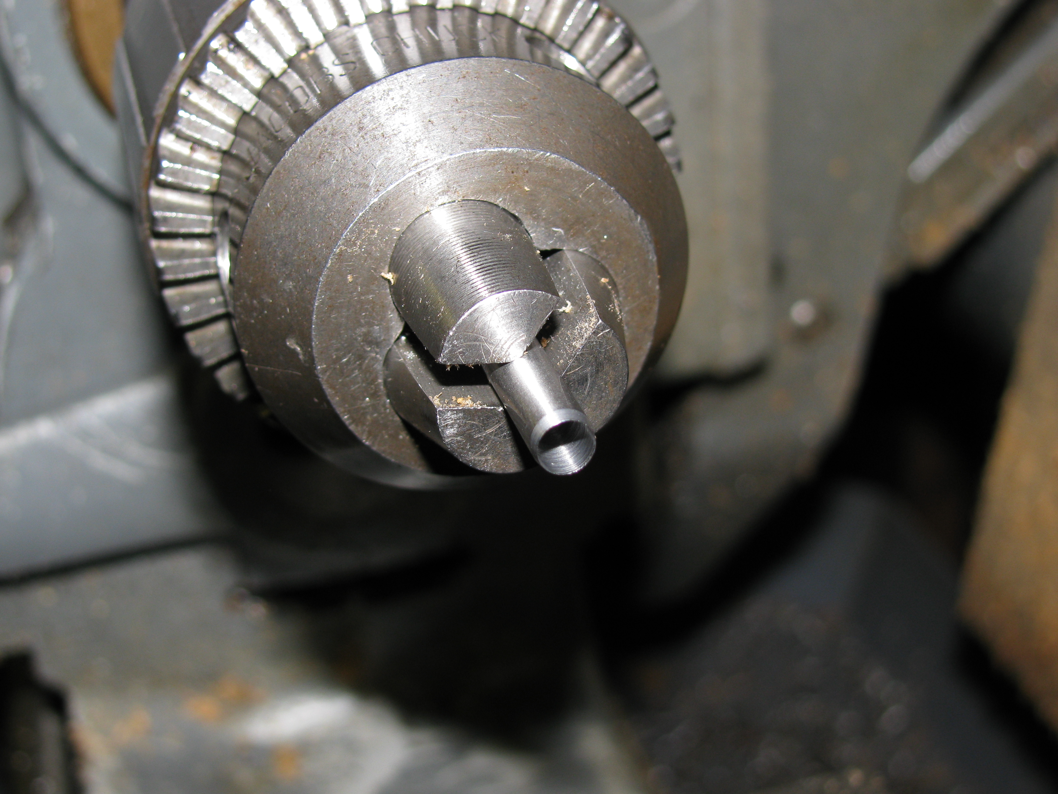
I turned a shoulder on length of 5⁄16″ mild steel to fit the drive flange. At ¼ thou over nominal it was a fit, but could usefully have been a tiny bit tighter.
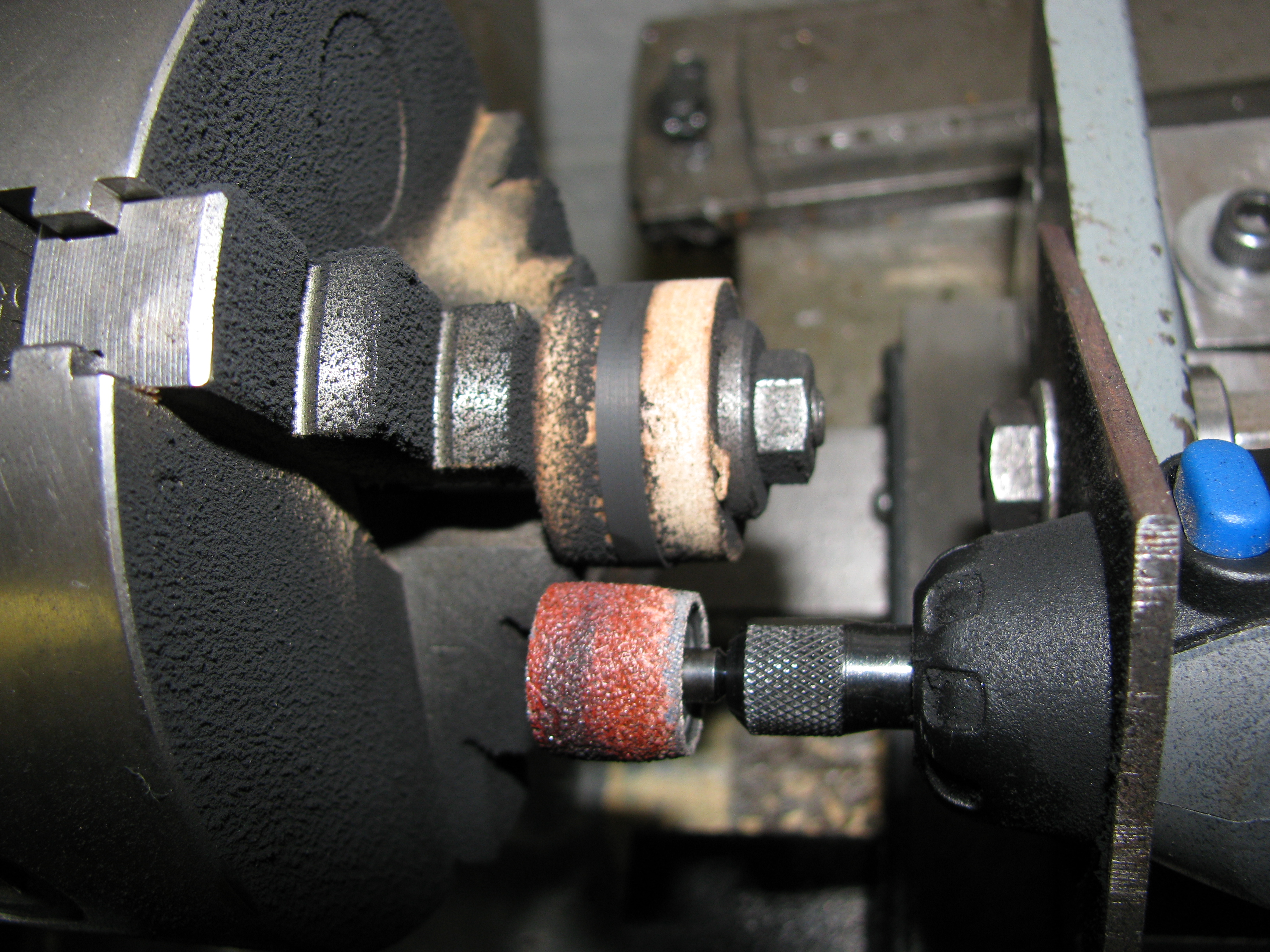
I had decided that some simple and adequate jigs for the doughnut could be made from MDF. Snipping doughnut blanks from the sheet I managed to cut two too small before getting one right. I turned a pair of collars in MDF to sandwich the blank between for grinding the OD. A piece of mild steel plate with two holes in allowed the Dremel to be mounted on an angle plate on the cross slide. After all the messing about, it actually took about two minutes to successfully grind the OD of the doughnut.
For drilling the ring of six holes in the dougnut I made a cutter from 3⁄16″ silver steel, drilled carefully to preserve concentricity, 4.3mm right through, leaving a 10 thou wall thickness tube, and taper turned the bore to form the cutting edge.
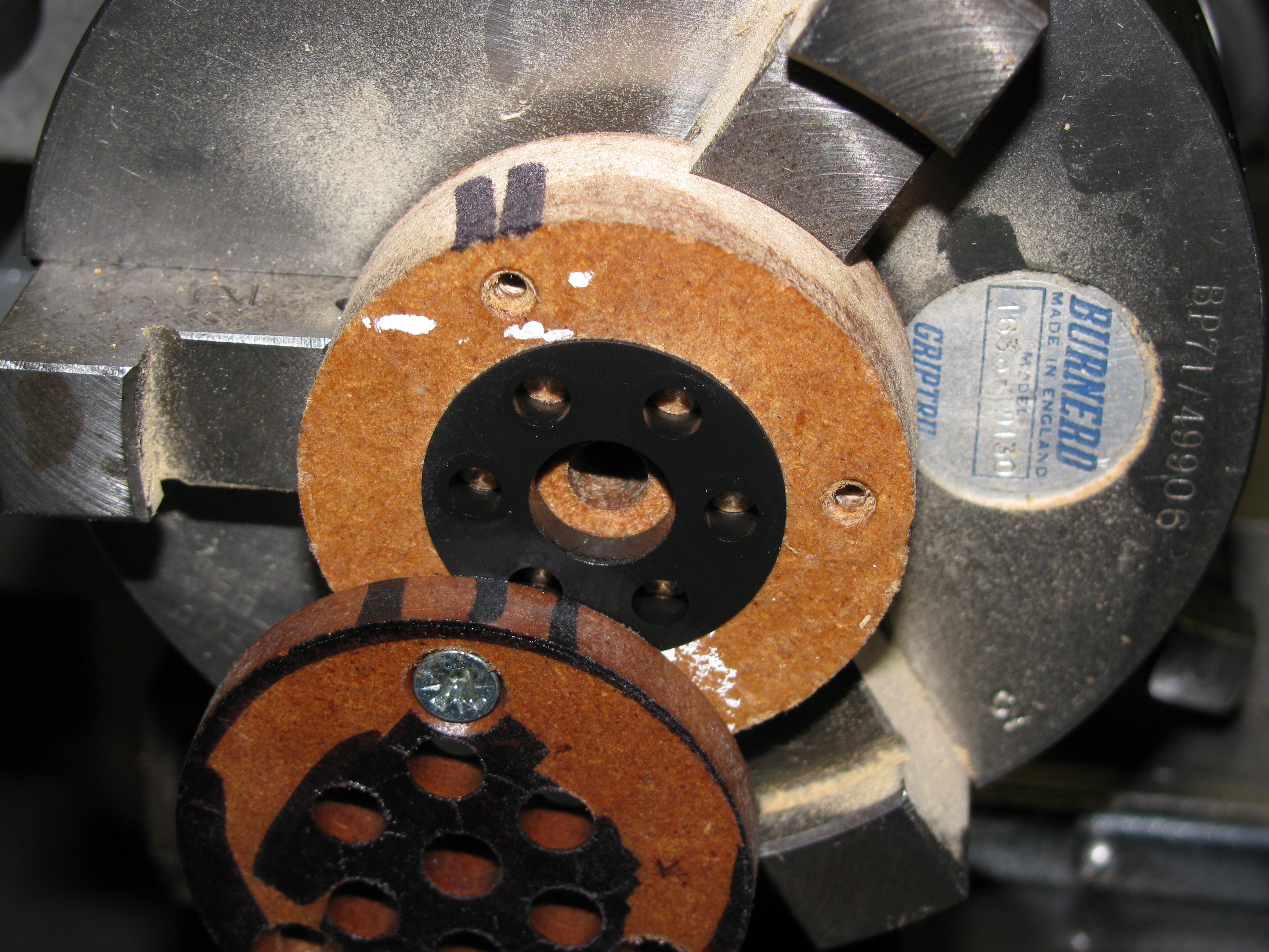
I cut two more pieces of MDF and put ¼″ holes in the middle, turned them mounted on a ¼″ stub mandrel, and drilled a ring of three holes for screws to hold the pieces together. With the thicker piece in inside jaws in the chuck I bored a recess to take the doughnut, but 0.020″ shallower than the thickness of the rubber so that it will be clamped in place by the cover plate. With the chuck transferred to the dividing head, I drilled six holes ¼″ diameter in the MDF cover plate and then clamped the blank in place and used the 3⁄16″ cutter to make the holes in the doughnut. I was really pleased with the result. (about 5½ hours)
2011-11-03 - Drive pins
The mild steel hexagon rod I was using was a shade over the nominal 0.110″ size and would not fit between the jaws of a 6-BA spanner in all positions, so I spent a while rubbing them on a stone to get them to size. Unsure if the end that fits into the flange wants to be domed, I try one. It looks fine. Three more studs made at one end; face, turn shoulder to length and diameter, undercut the thread run-out, chamfer, die-cut the thread, use a small fine file, stone and 800 grit wet-or-dry in the lathe to form and polish the domed ends. (1¼ hours)
2011-11-04 - Nearly finished

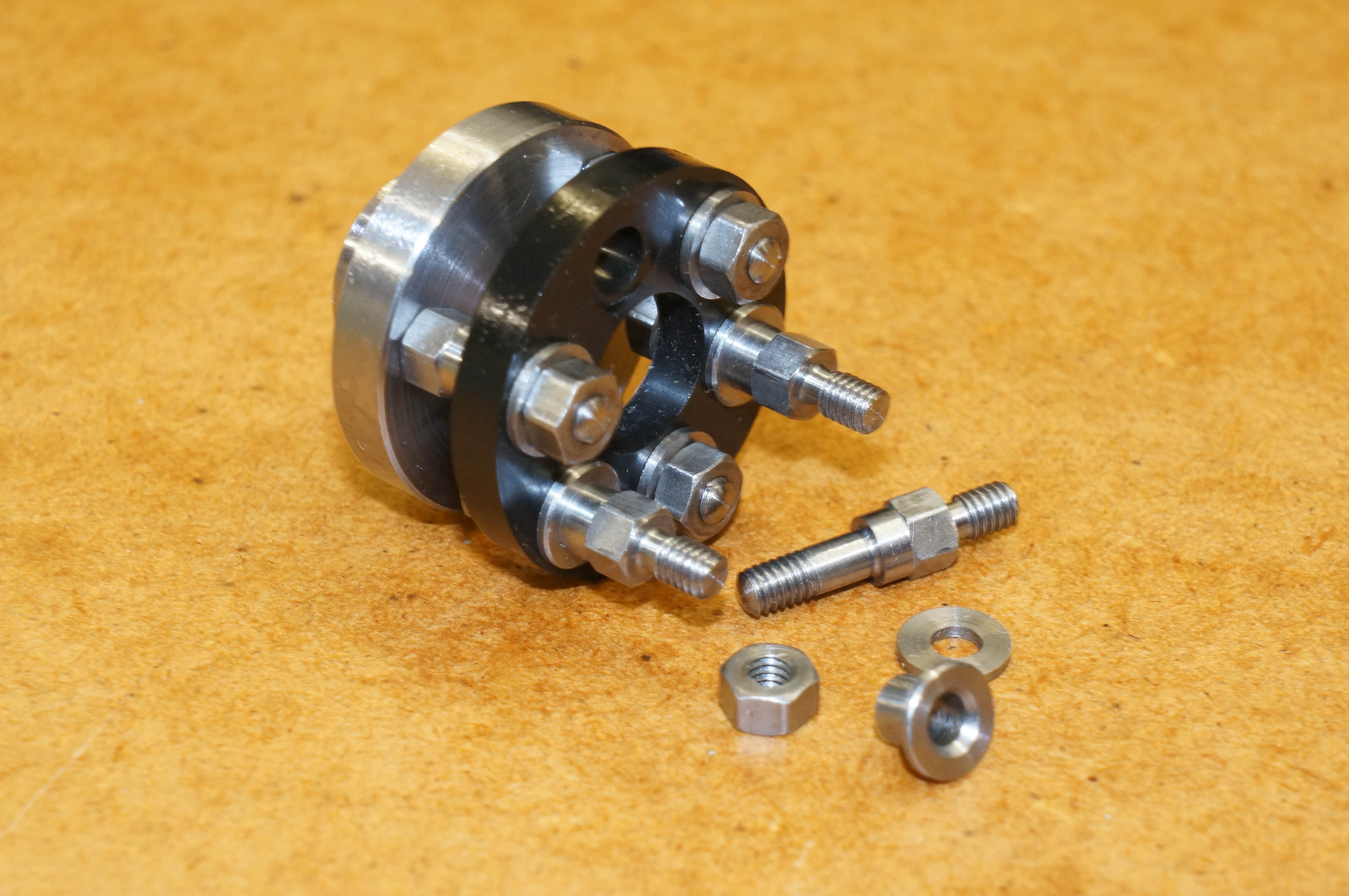
To hold the studs for the second operation I chucked a short piece of 3⁄16″ material, faced, drilled and tapped it to take the pins. I machined the outer ends of these one process at a time working to dial readings, thinking it was easier to change from stud to stud than to change and reset tools. I used the top-slide for turning to fixed length. I turned the flats off with a 30° tool to chamfer the end of the nut, turned the shoulder, chamfers, die-cut the threads (no run-out needed this time), chamfered, domed and polished (not too much).
With a trial assembly it looked pretty darned good. To finish off I need to chamfer the washers and make some nuts with a 6-BA hexagon and 5-BA threads, but that can wait.
Now I can get back to the timing gears. (3 hours)

.