
Cylinder Barrels

Design
The waterways to the head are rather disturbing. As the drawing is drawn they clear the outside diameter of the liner shoulder, but as the drawing is dimensioned, they are tangential. The 1⁄8″ holes shown would certainly need to be close in order not to be too close to the outside edge. A slightly narrower oval passage might be better.
Are the head bolt holes supposed to break into the water jacket?
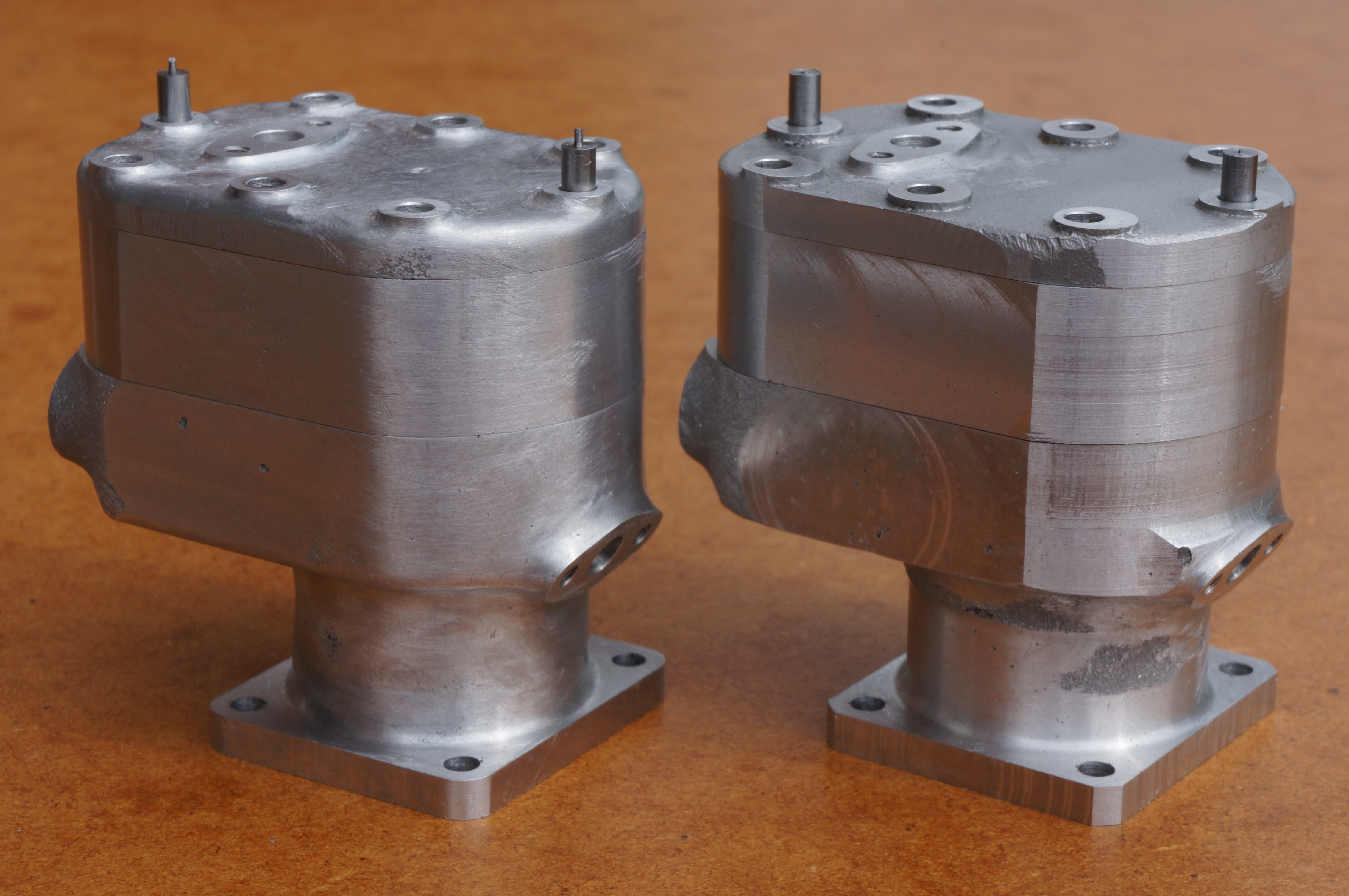
Castings
The rather lopsided castings have sat on my desk for several days for ruminations. Some of the unmachined surfaces are going to need attention if the engine is to look anything other than extremely agricultural. They will need sand-blasting to hide the evidence. The barrel and underside of the jacket are hardest to do anything with because the water inlet boss prevents turning. However, because there is some mismatch between the two halves of the castings something will probably need to be done to make the height of the jacket and barrel more equal on both sides. The face under the barrels could be turned part way and continued with a combination of part cuts by hand rocking the chuck and some tickling with a ball-nose end mill. The periphery of the jacket will need fettling, as it is slightly too wide in parts, asymmetrical, and will not match the heads and covers. This may need to be done in stages as the parts emerge.
It looks as if it will be best to set up with the bottom face of the water jacket running true to get a cut across the foot. The chucking piece can be cut off with a hacksaw. The casting can then be clamped by the foot to take a good cut across the top. At this stage the plan profiles of the barrel and water jacket can be rationalised to find a centre. The flanks of the jacket could be milled flat at the same time as the bolting flange. This would provide a clearer datum and assure there is sufficient metal each side. Much depends on getting a match for the head and cover, which should also be roughed out. Final profiling would probably be done as an assembly.
2010-07-18 - Initial roughing cuts
Not having touched the engine for 3 months, I wanted an easy job to get back into the swing, so I took roughing cuts to clean up and remove a bit of the spare on the top and bottom faces. The top face was done first, lining it up pretty much by eye to get the underside face of the water jacket running reasonably true. Accurate measurement and planning for later stages can now be carried out. (1½ hours)
2012-02-20 - Measuring
With the top surface rough machined, it can be used as a datum to get accurate dimensional and geometric measurements of each casting. I paid particular attention to the profile of the top surface as previous cursory examination has shown that they are a bit skimpy in parts. If the registration of the two halves of the moulding box had been perfect, then there would have been no problem, but that is pretty unlikely. With modern bonded sand moulds, more accurate registration can be put in by the pattern-maker, by using an oddside, so that the sand does the registration rather than the probably worn pins and holes on the moulding boxes. In fact the worse cylinder is only about 1⁄64″ out, and the fact that this causes a problem shows just how tight thing are. In plan, the curve of the water jacket round the barrel is not symmetrical. The radius on the flywheel side is undersize, meaning some metal will need to come off, while on the timing-end side it is too large, and it will be difficult to find enough metal. As there is also a slight lack of metal round the valve-guides, it is hard to balance the final position of the big hole. It looks as though I will end up with the corners of the cylinder heads round the valves either slightly overhanging the cylinders, or, as there is a reasonable amount of meat in this area, being reprofiled a bit. Because most builders will want to fettle the cylinder, head and cover so that the profiles match at the joint line, and because the sealing face width is very small even without going inside the design profile all these castings really ought to be on the plus side of nominal all over. I made accurate CAD drawings of the actual castings. This helps a great deal in working out how to prevent bits of the desired finished part from sticking out of the casting. (4¾ hours)
2013-03-23 - Second roughing
I find I have come back to the cylinders rather unexpectedly. I wanted to have another go at boring the connecting-rod little ends, but, unsure exactly what diameter to aim for, I want to make the pistons, and to make the pistons I need finished cylinder bores, which in turn need finished cylinders. Another direction would be grinding the cams, but no grinder yet, so here we are.
There is still a total of about 1⁄8″ to come off the overall height of the cylinders, with something over 0.050″ to come off the top surface. To start with I took 50 thou off the bottom flanges. No 1 was straightforward. Measurement of No 2 had shown that it needed tilting slightly to level up the unmachined underside of the water jacket, so this was machined with 0.015″ of shim under the valve port end.
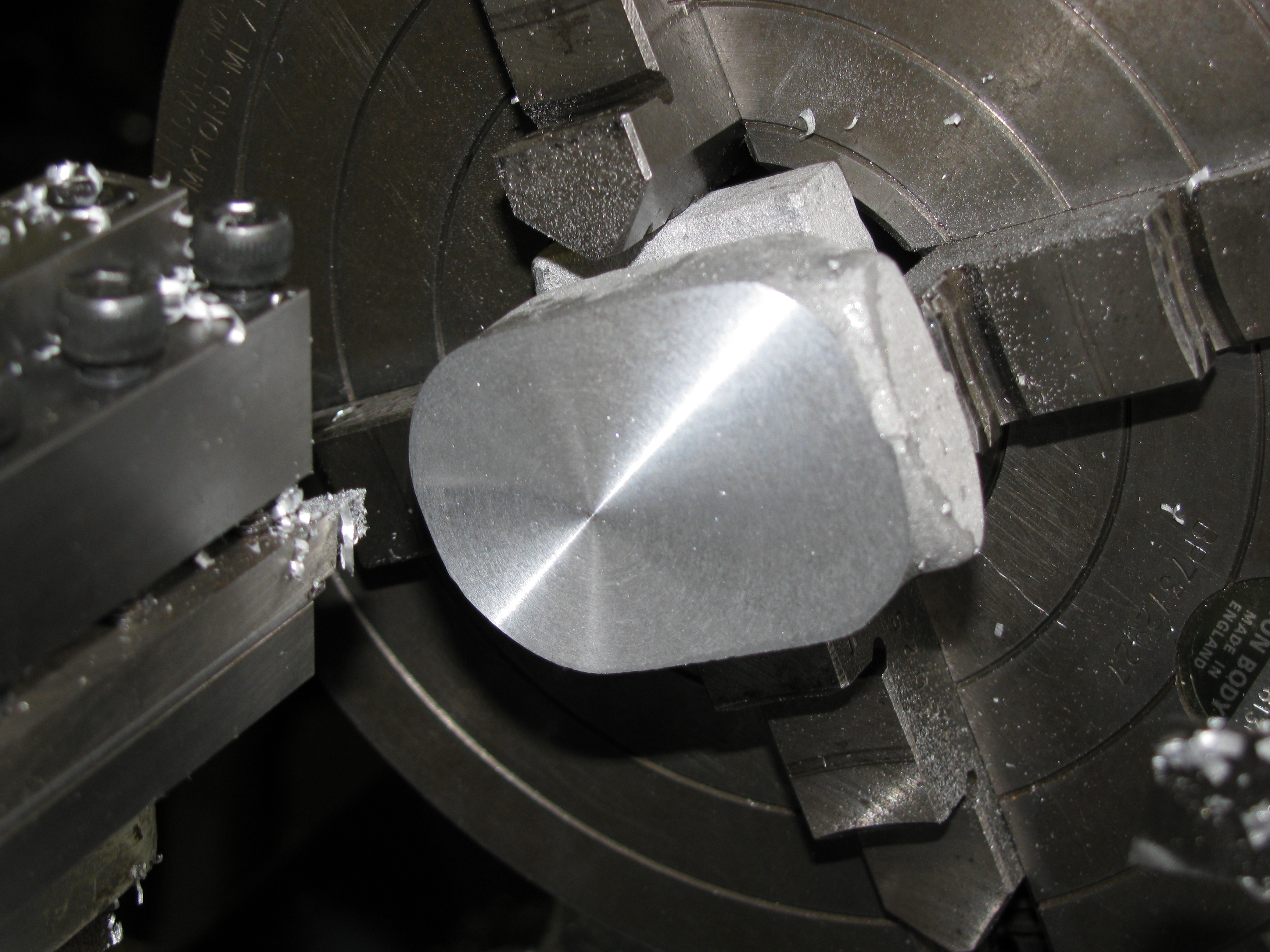
To work on the top surfaces, the mounting flanges are just barely big enough to bed against the 4-jaw chuck body. This enables an initial rough bore to be drilled at the same setting. I took an average of 40 thou off the top face of cylinder No 2 at 425 rpm and drilled a hole, opening it out to 5⁄8″ at 615 rpm. This leaves a shade over 1⁄32″ remaining to take off the height. I need to remember a finishing allowance for taking a cut over the casting with the liner and valve-guides installed, A thou for lapping, and that I want the cylinders to end up 0.003″ oversize to compensate for the slightly low crankcase top. After machining No 1 too, this will need the finish cuts to be about equal top and bottom, while No 2 will need more off the top. (1¾ hours)
2013-03-24 - Third roughing
With the top and bottom faces only needing finishing cuts, the next job is to optimise the machining in plan. To do this, initial datum surfaces need to be established. The water jacket is slightly over finished width, so flats can be milled on each side. At the same setting, the sides of the mounting flange can be roughed out, 1⁄32″ further in. I took about 0.012″ off the timing side of No 2 water jacket, and just enough to establish a flat on the flywheel side, leaving it about 10 thou over finished width. I treated No 1 cylinder the same. It ended up not quite parallel with at least 0.015″ to take off the foot, while the top has as little as 0.012″ in places. The milling vice is handy, but not ideal for getting the greatest geometrical accuracy. A different set-up will be needed for the finishing cuts.
Meanwhile, to establish the third datum plane I roughed out the port faces. There was quite a bit of meat on these, and I took 70 thou off in two cuts, leaving 1⁄32″ for finishing. Milling at 1000 rpm, I got a bit of squealing doing No 1, and No 2 machined oddly, going in snatches. I think the light cuts over the cast surface of the sides, possibly with a bit of sand still embedded, has taken the edge off the milling cutter. At the same setting, but 5⁄8″ further in, I took an cut over the back of the mounting flange, and then reversed the casting and took a cut off the front, again leaving it with about 1⁄32″ more to come off. (2¼ hours)
2013-03-25 - Profile template

Because of the difficulty of getting a top surface complete to the design profile, I decided to make a template to check. I used a bit of 1⁄8″ black steel plate. Having milled it with parallel sides, to width, with accurately square ends, and exactly 0.01″ too short, I co-ordinate drilled and reamed holes for the centres of the radii. Using the rotary table I then milled the radii. Looks good. Tidy up. (3¾ hours)
.
2013-03-28 - Final position and setting up
Now to examine the cylinders with the help of the template. No 1 does not present a problem. The cylindrical barrel is accurately centred on the water jacket, and the top surface allows some scope for optimising the endwise positioning. The plan is to take 5 thou off each side and 26 off the port face.
One of the potential problems is having enough metal in the cylindrical barrels under the water cooling inlet flange. Reducing the amount taken off the port face will help here, and with allowing the rounded part of the water jacket to be profiled. With a flat held against the front face of the mounting flange, a drill can be use to gauge the gap. Coincidentally both cylinders just allow a 2.4 mm (0.092″) drill shank in the gap. On No 1 cylinder, the flange currently measures 1.180″. Taking 25 thou off the back, and 30 off the front will just do what is needed.
Looking now at the sides of No 2 cylinder, The flywheel side of the jacket has a couple of small cavities, so it would be useful if more metal could come off that side. On this casting, that is reinforced as the cylindrical barrel is offset by about 15 thou towards the timing side. As it has an offset, the cylindrical part of this one is naturally the narrower, at 1.033″ wide, but by turning to 1″ diameter it looks as though it will clean up.
With the template on the top surface, it has to be skewed slightly to get a complete fit, and wants a nominal 20 thou off the port face. The foot flange is 1.186″ so taking 0.020″ off the back will leave 0.043″ to come off the front. Because the mould halves were offset, this casting needed more initial filing to prepare, and the barrel only has 15 thou to spare front to back. Again, this should just about work out right.
I started to set up for the finishing cuts, using an angle plate instead of a vice this time for greater accuracy. With the vertical slide set dead square, the angle plate was adjusted level axially by shimming the bottom edge with a cigarette paper, and then set within a thou of level across the lathe bed. No 2 casting was set up with a shim to skew it the required 5 thou. (2½ hours)
2013-03-30 - Finish milling
As I have to do a number of set-up changes, and only need light cuts, it will be OK to use the 3-jaw chuck to hold the milling cutter. I started out with the same 9⁄16″ cutter as the best for the job even though it is no-longer dead sharp. With the first cut, on the timing side of No 2 jacket, it is clear it not cutting well. However, the side of the foot has to be done at the same setting, with 1⁄32″ feed from the leadscrew handwheel. Using a ¾″ cutter instead, I milled the other side. The jacket came out well, at +0.0015″. Oddly the foot is slightly tapered and the finish a bit lumpy from the dull cutter. This is no great problem as I will be using the side of the jacket as the datum, and the foot will be finished and sand-blasted anyway. At a third setting, and after squaring off the port face and checking again with the template, it needs a further 0.014″ cut to finish. The back of the flange was finished at the same setting. Finally it was turned to finish the front of the flange, taking 0.043″ off, and then a finishing cut of 3 thou to leave the foot +0.001″. With the flange machined, I again used a flat and probing rods to check the barrel. It will clean-up to 1″ diameter.
With No 1 cylinder set up, I took 5 thou off the flywheel side, leaving 7 thou for the other side. This left the jacket +0.0025″ and the flange +0.001″, both parallel. Checking the top face again with the template, anything between 0.005″ and 0.027″ could be taken off the port face.
Setting for cutting the portface by clocking the side of the jacket is not perfect, as I know the lathe is facing slightly concave (as it should) this means that faces milled by traversing the cross-slide will be a trace out of square. I took a 15 thou cut off the port-face, and another 2 for finishing. With the leadscrew advanced five turns exactly, the back of the mounting flange was also finished. This leaves a nominal 0.040″ to take off the front face. After re-mounting, I took 0.038″ off to leave 2 thou for finishing. Again, it is going to be possible to turn the barrel. In fact this one would clean up a bit larger than 1″ if that were needed. (4¾ hours)
.
2013-04-02 - Dogs
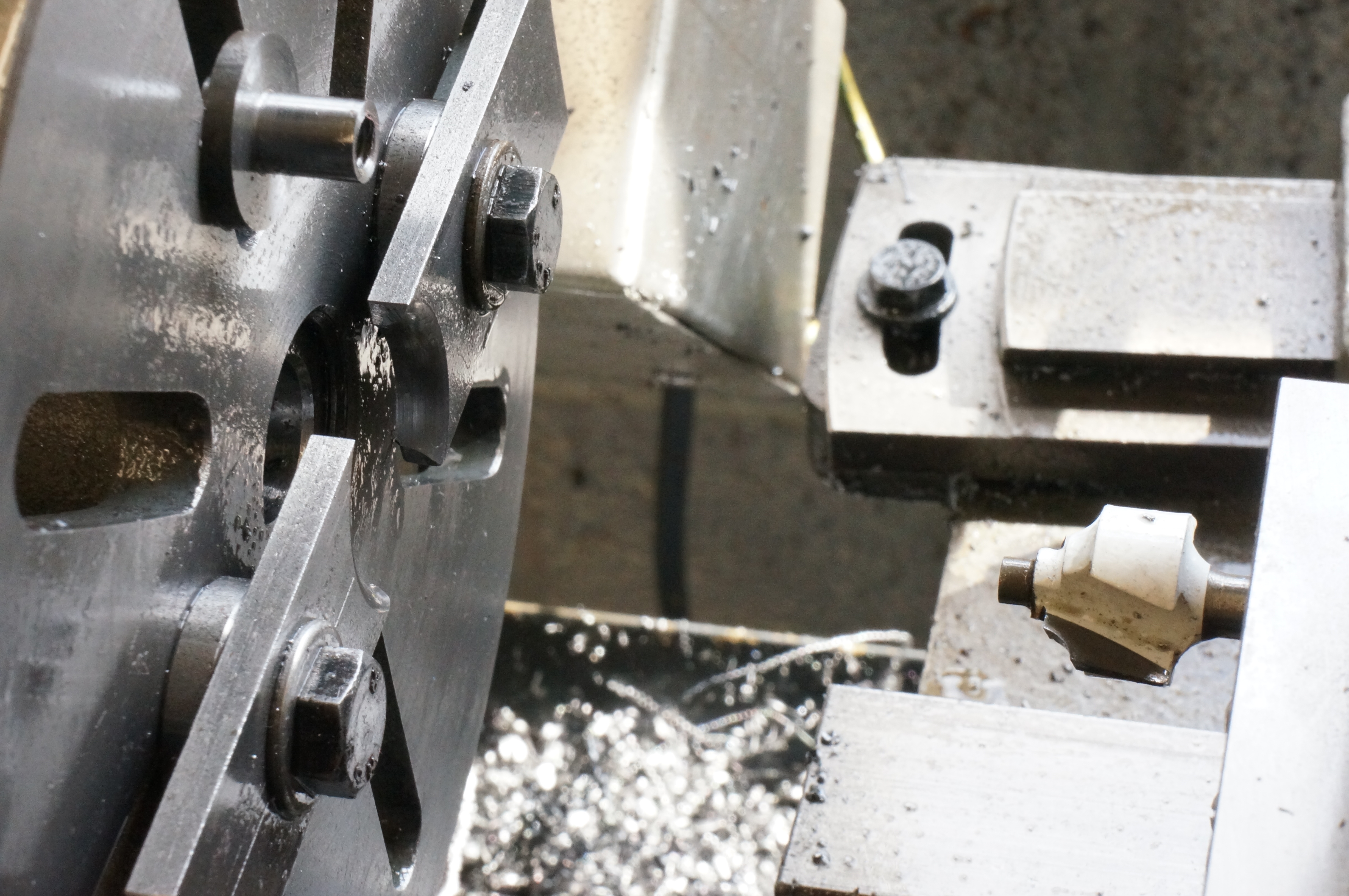
In making a pair of clamping dogs to hold the cylinders to the faceplate, I wanted a generous radius. Not having a suitably ground tool to hand, I had an inspiration and borrowed a router bit from the woodworking department and stuck it in a ¼″ boring bit holder. This ruse worked a treat, and has not taken the edge off the carbide cutter. (2¼ hours)
2013-04-03 - Finish boring No 1
Considering the top faces of the cylinders, I need to leave an allowance of 0.003″ oversize, 0.001″ for lapping; and finish facing cuts over the tops of assembled barrel, liner and valve seats of, say, 0.005″ and 0.002″ or at least 0.011″ in all.
Measuring up No 1 cylinder, the thinnest part of the water jacket allows just that much, and the overall height is 0.031″ thou over the nominal 1.25″, so there is exactly 0.020″ to be taken off the bottom for finishing. As the depth micrometer is reading slightly off, I want to end up with a height measurement off the faceplate of 1.262″. The top is not finished so softening is not needed.
I had quite a fight to get the bolting flange running true, but eventually got both pairs of opposite sides within 0.0005″. With a freshly honed tool, I took facing cuts of 15 and 4 thou at 850 rpm to get the required height. I turned a total of 0.045″ off the corners of the flange to reduce the amount of work that will be needed to file the radii.
For finishing the bore I used the ½″ boring bar at 850 rpm. After a trueing cut, I took a further three cuts of 20 thou. The surface finish is not bad, certainly good enough for Loctite. Mercifully, it is also pretty accurately parallel. Measured 0.783″. With a further 28 thou to go on diameter, I took a cut of 10 thou. Measured 0.8027″. A 3 thou cut, trying a smear of the Rocol RTD I am finding so useful on these castings. In this case it was no improvement on my usual 50/50 mix of neat cutting oil and paraffin. Measured 0.8093″ After a 1 thou cut, I measured 0.811 over the telescopic gauge, and the plug gauge, made initially for boring the crankcase, will not enter the hole. Another 1 thou cut should make the hole 0.0005″ over the nominal 13⁄16″, which is what we want. Take a final thou. The plug gauge fits without tightness or shake, and the telescopic gauge measures 0.8128″, which is spot-on.
While it would be useful to machine the top of the bolting flange and outside of the barrel at this setting, the clamping dogs do not make it easy, and it is perhaps best left for another set-up. (3¼ hours)
2013-04-05 - Finish boring No 2
The top and bottom faces of this casting are not perfectly parallel, but it is at least 0.032″ over nominal size. The casing around the valves is at least 0.522′ thick. Taking 11 thou off the bottom will leave the top with the same 11 thou as No 1, and an extra 10 thou. After facing the flange, the height should be 1.271″ or a depth micrometer measurement of 1.272.
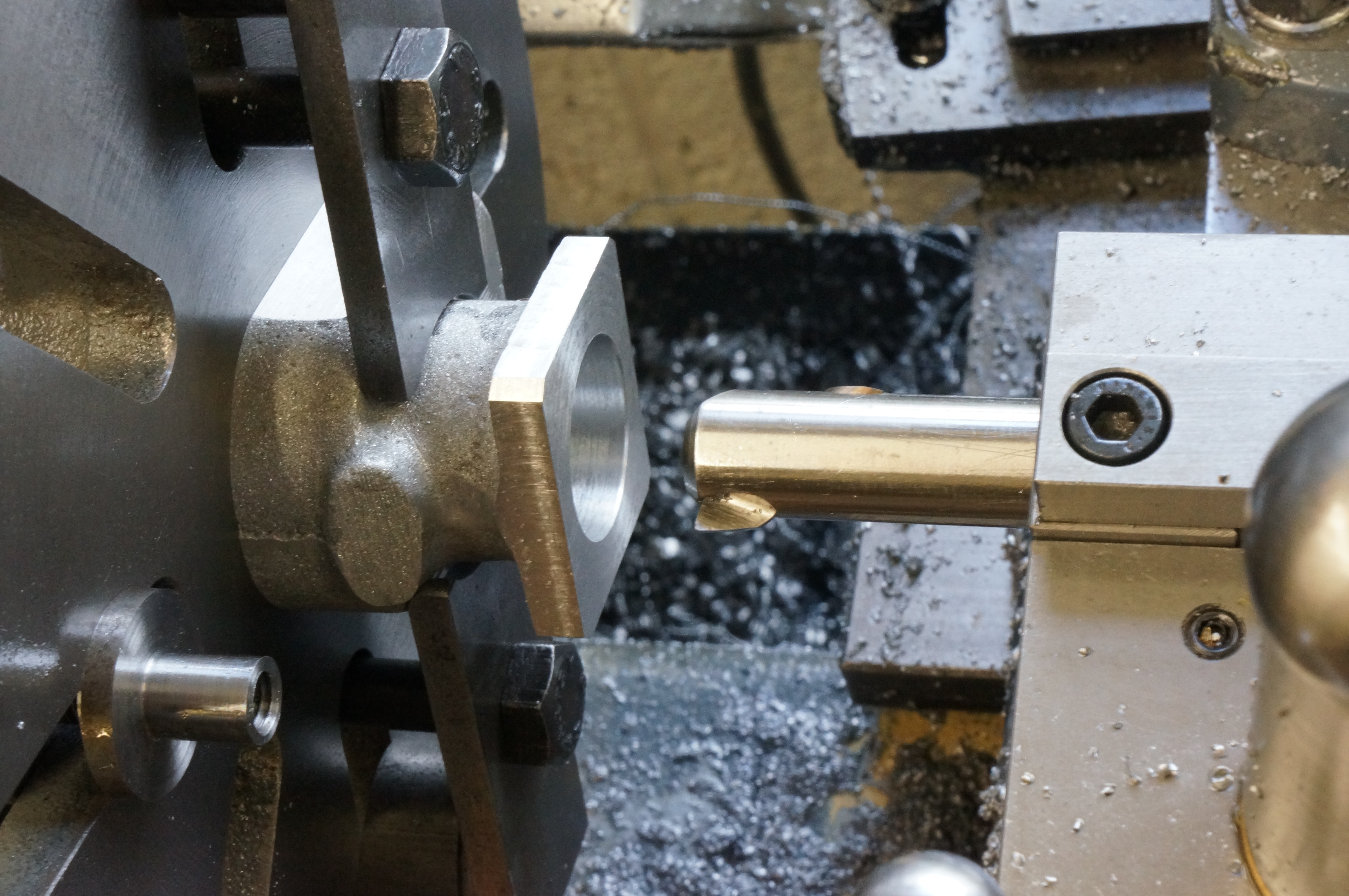
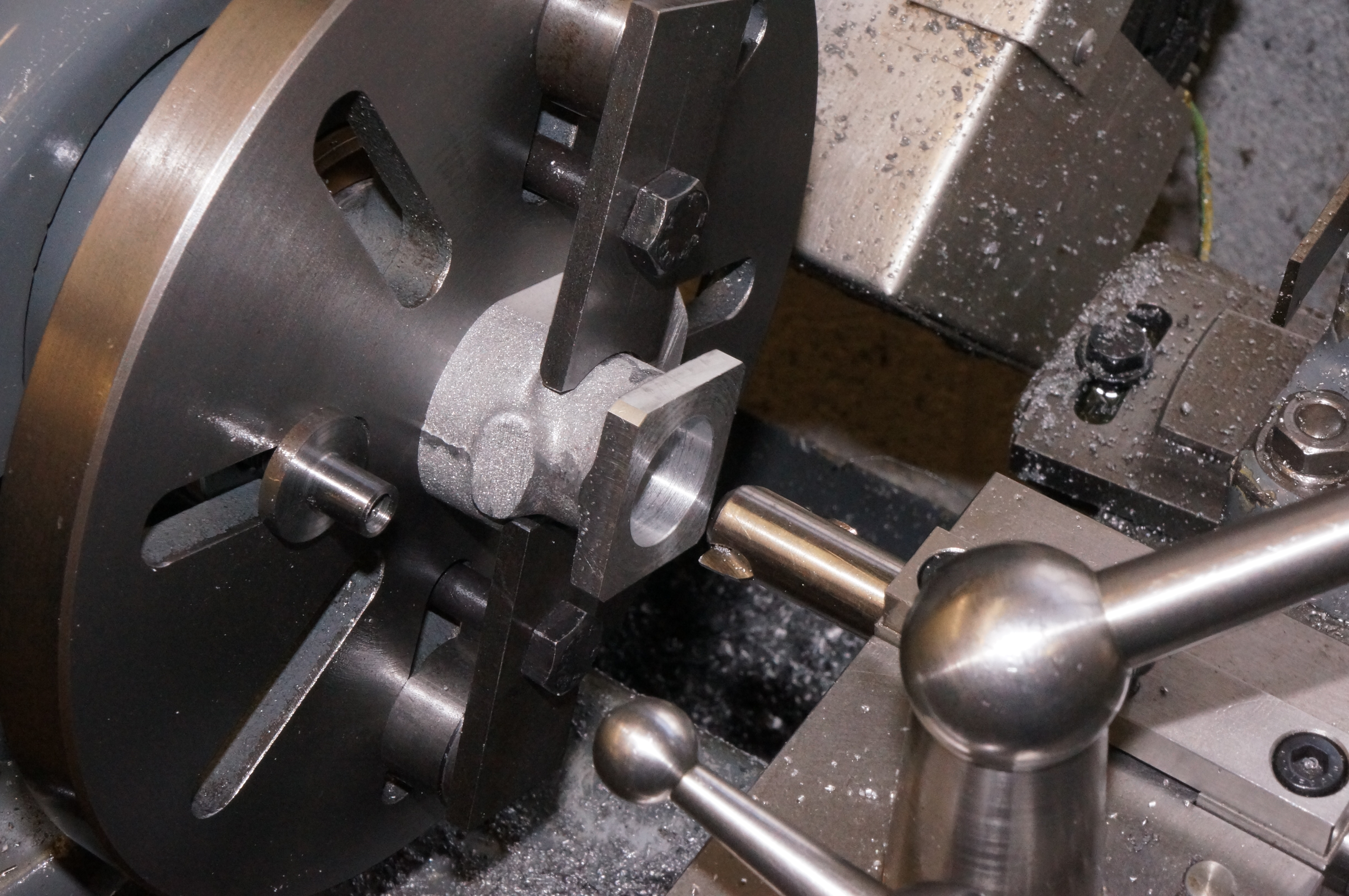
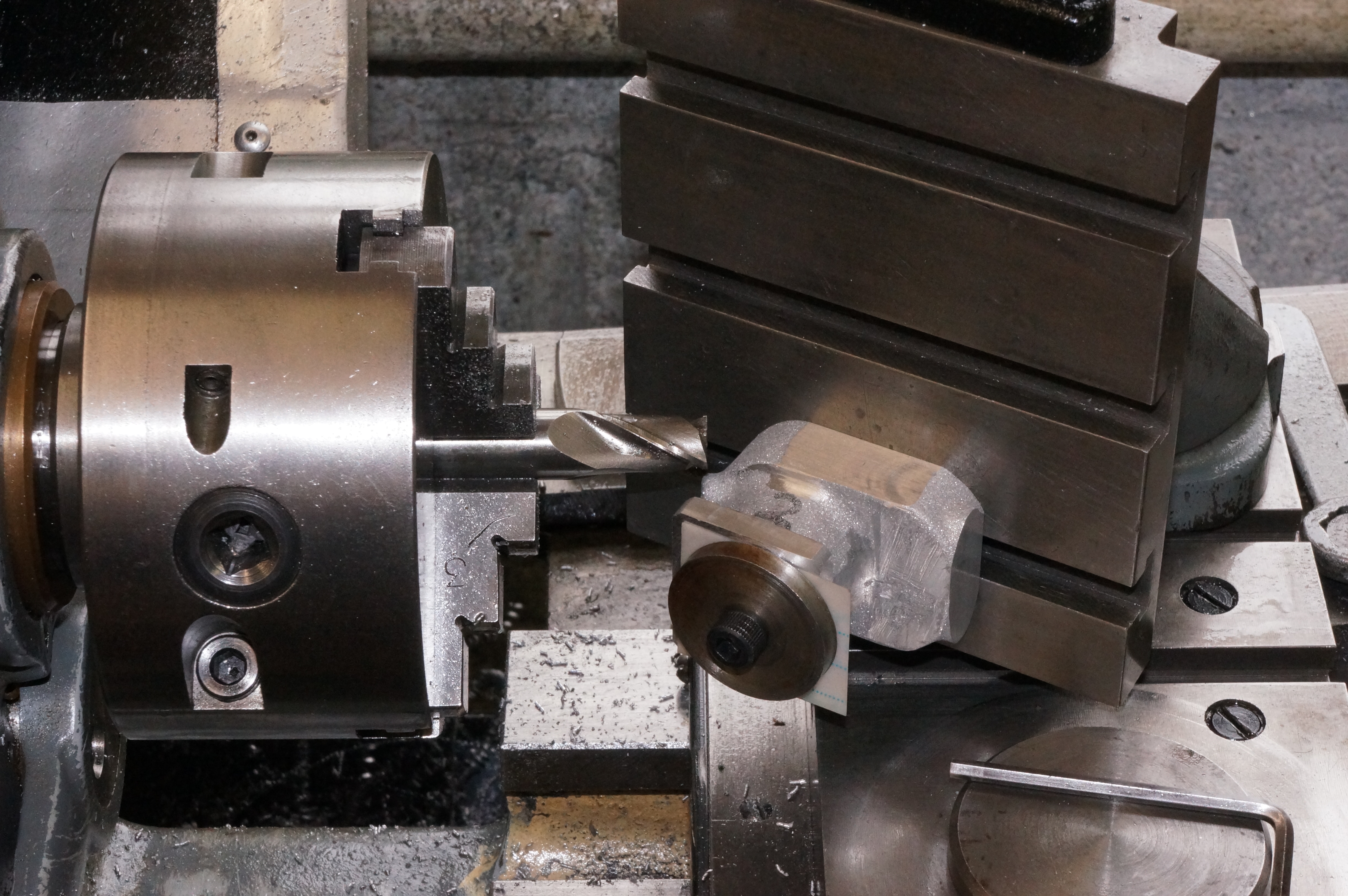
Setting this one true on the faceplate went much more easily. Three successively smaller cuts off the face brought it to the required size. Turning cuts of 30 and 15 thou truncated the corners. Boring was done as for No 1, with a 25 thou truing cut, 3 of 20 thou, then 10, 5, and 2-and-a-bit thou for a measured diameter of 0.8117″ and a plug gauge that almost starts in. After a final ½ thou cut, the plug gauge says we are good and the telescopic gauge measures 0.8128″. Wow - the bores are interchangeable.
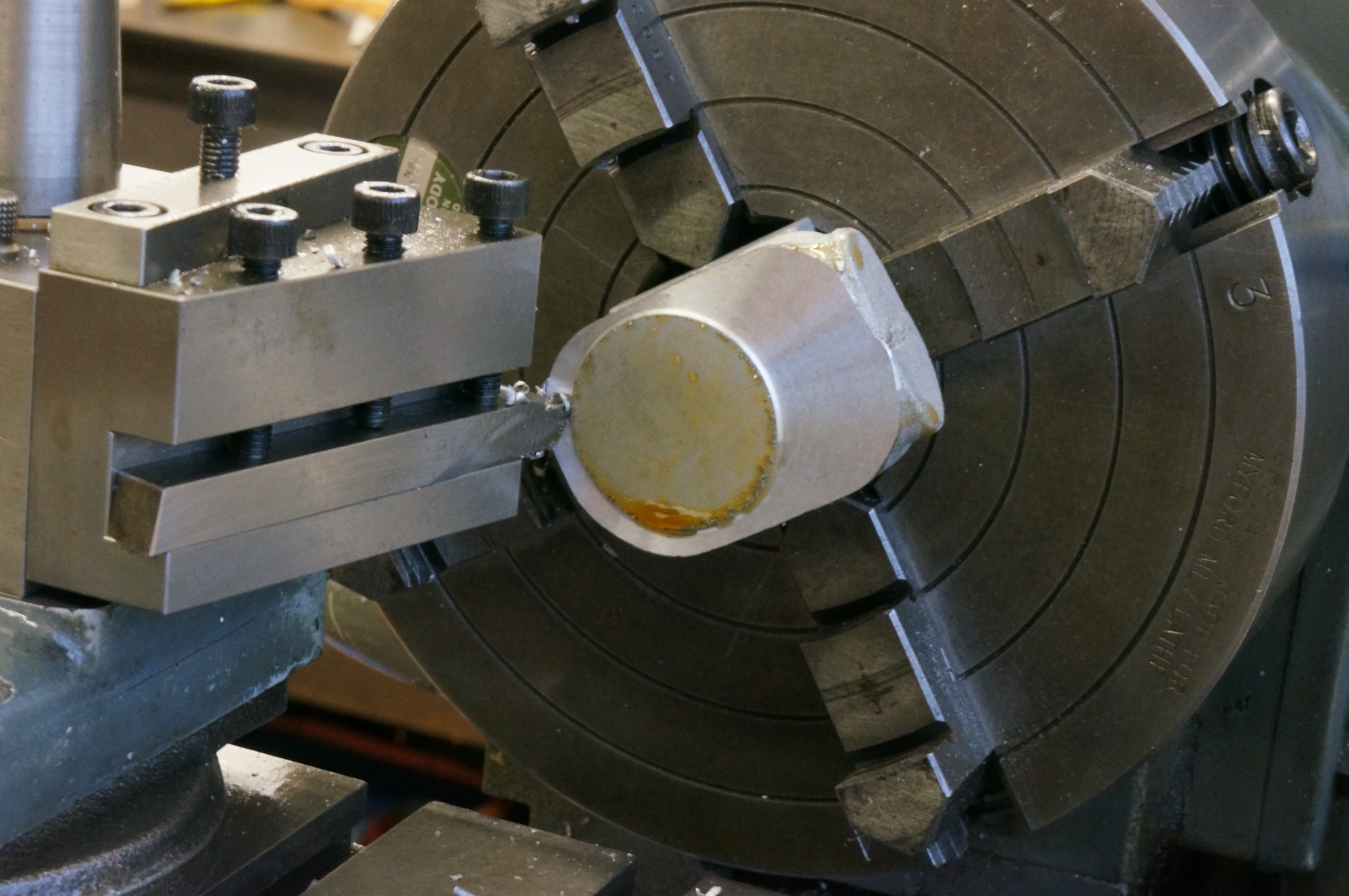
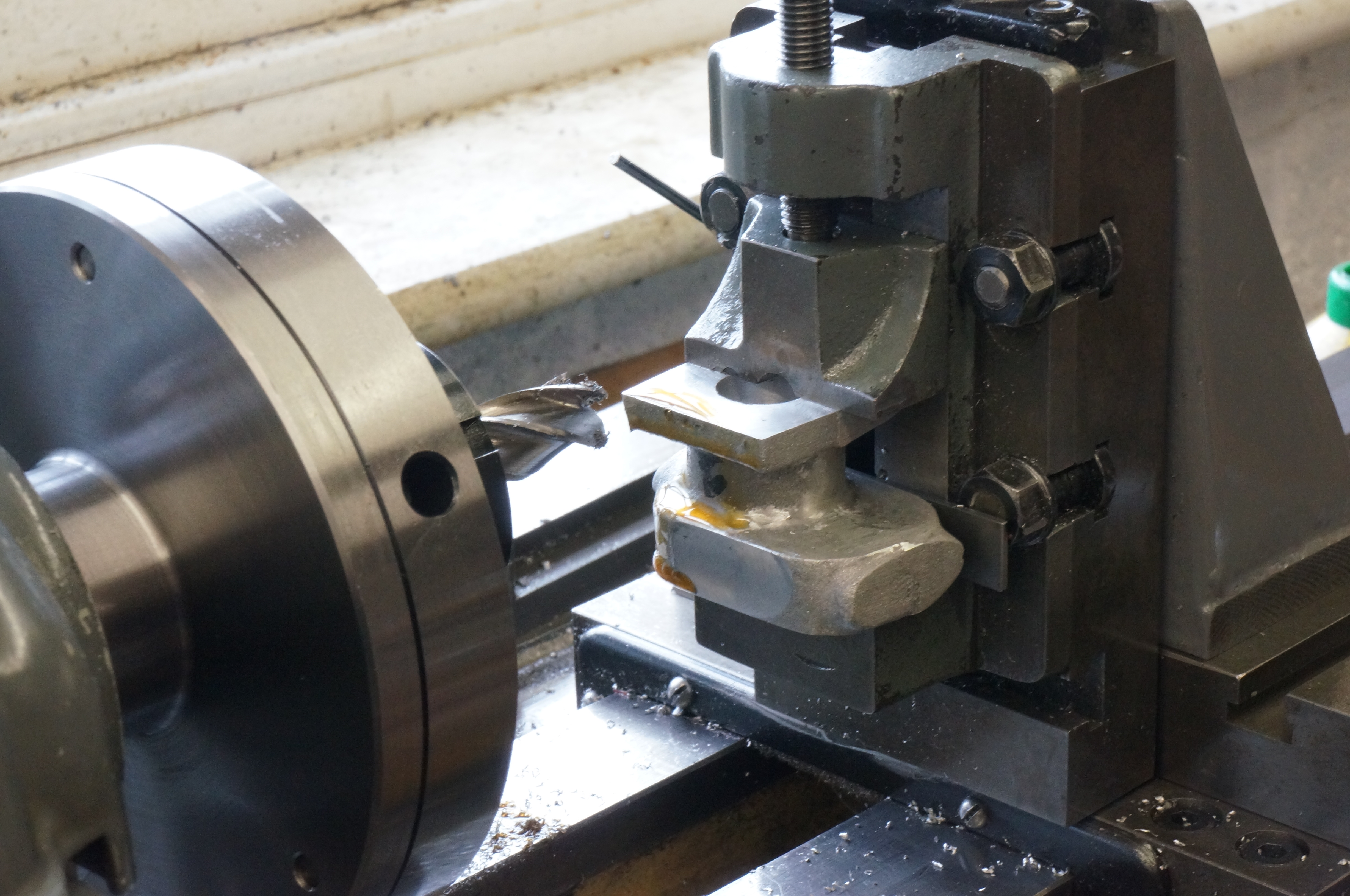
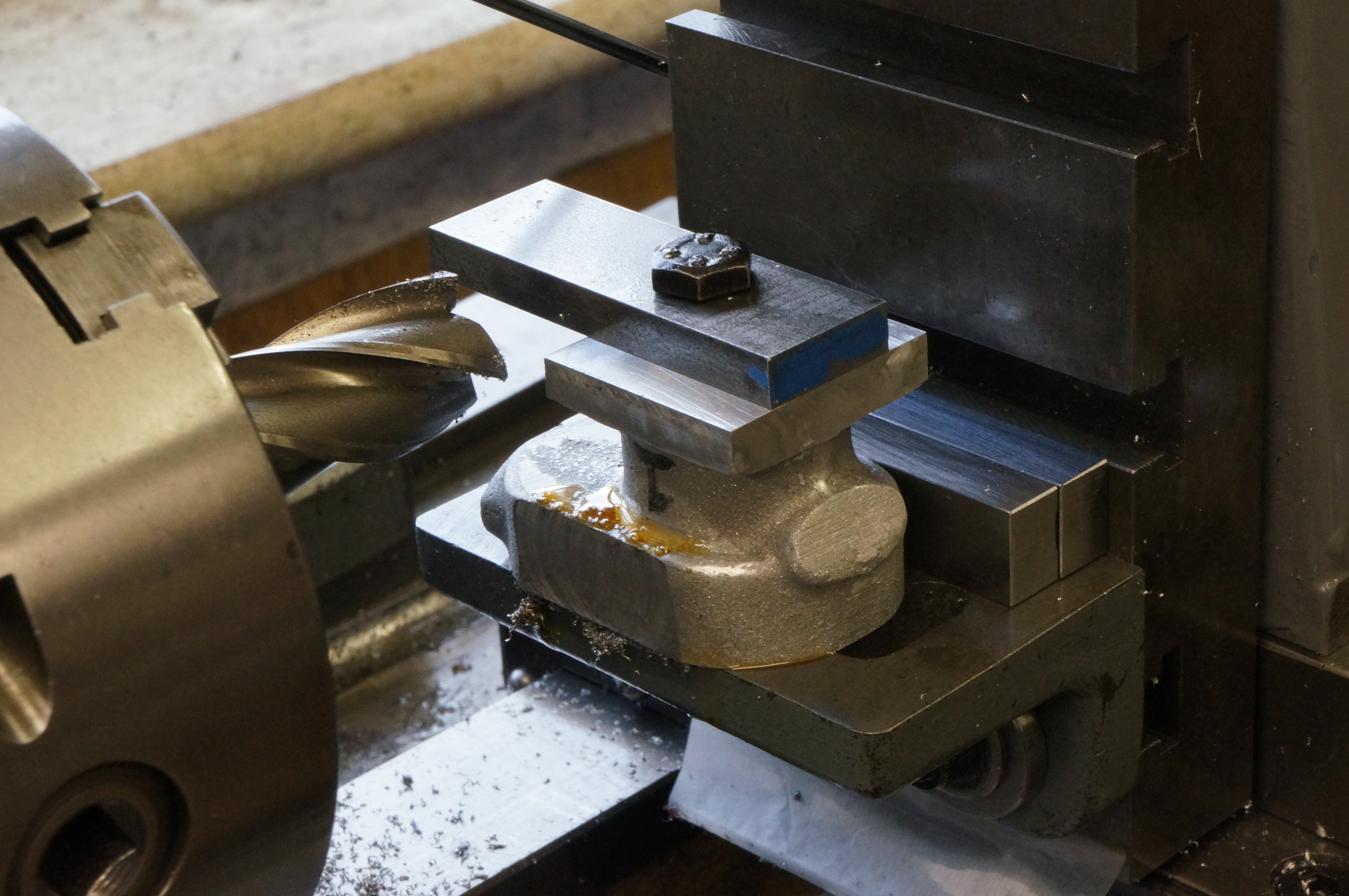
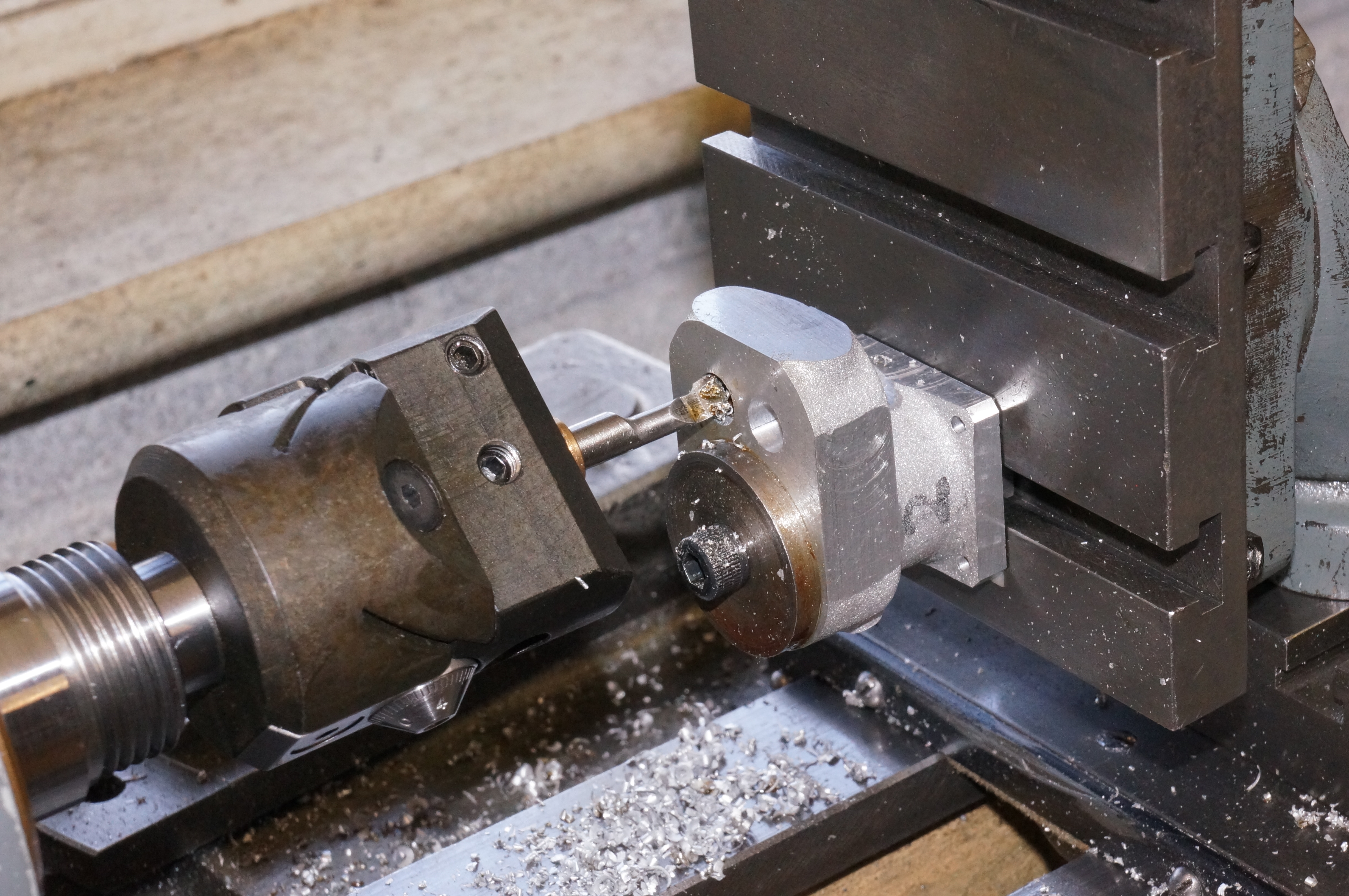
Finally I chamfered the edge, stripped the job down, and put it back because I had forgotten to take a photo of the set-up, did that, stripped down again, cleaned up the lathe and checked the height of the cylinder, a shade over 1.271″, just as required. (1¾ hours)
2013-04-13 - Water jackets

In my questionable wisdom I have decided that I did not want the cylinder head bolt holes to break into the water space. This involves a reduced depth of the recess at the top, and I have drawn a 45° transition between the two diameters. As the recess results in a wall thickness at the bottom of the jacket that is quite a bit thinner than elsewhere on the casting, I have shown a generous root radius to compensate. The first job was to grind a boring bit with a 1⁄32″ radius for the top of the recess and 1⁄16″ for the bottom.
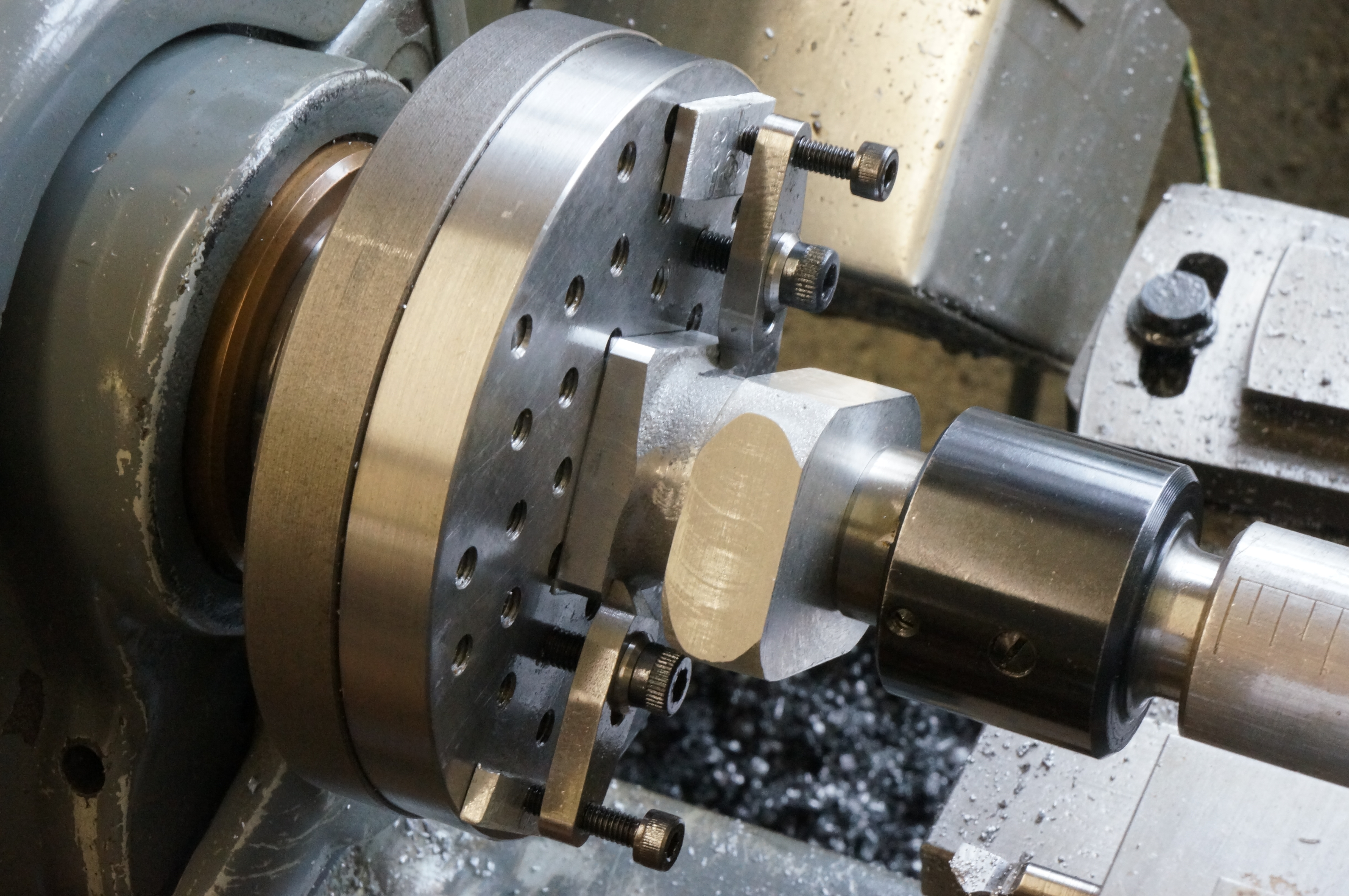
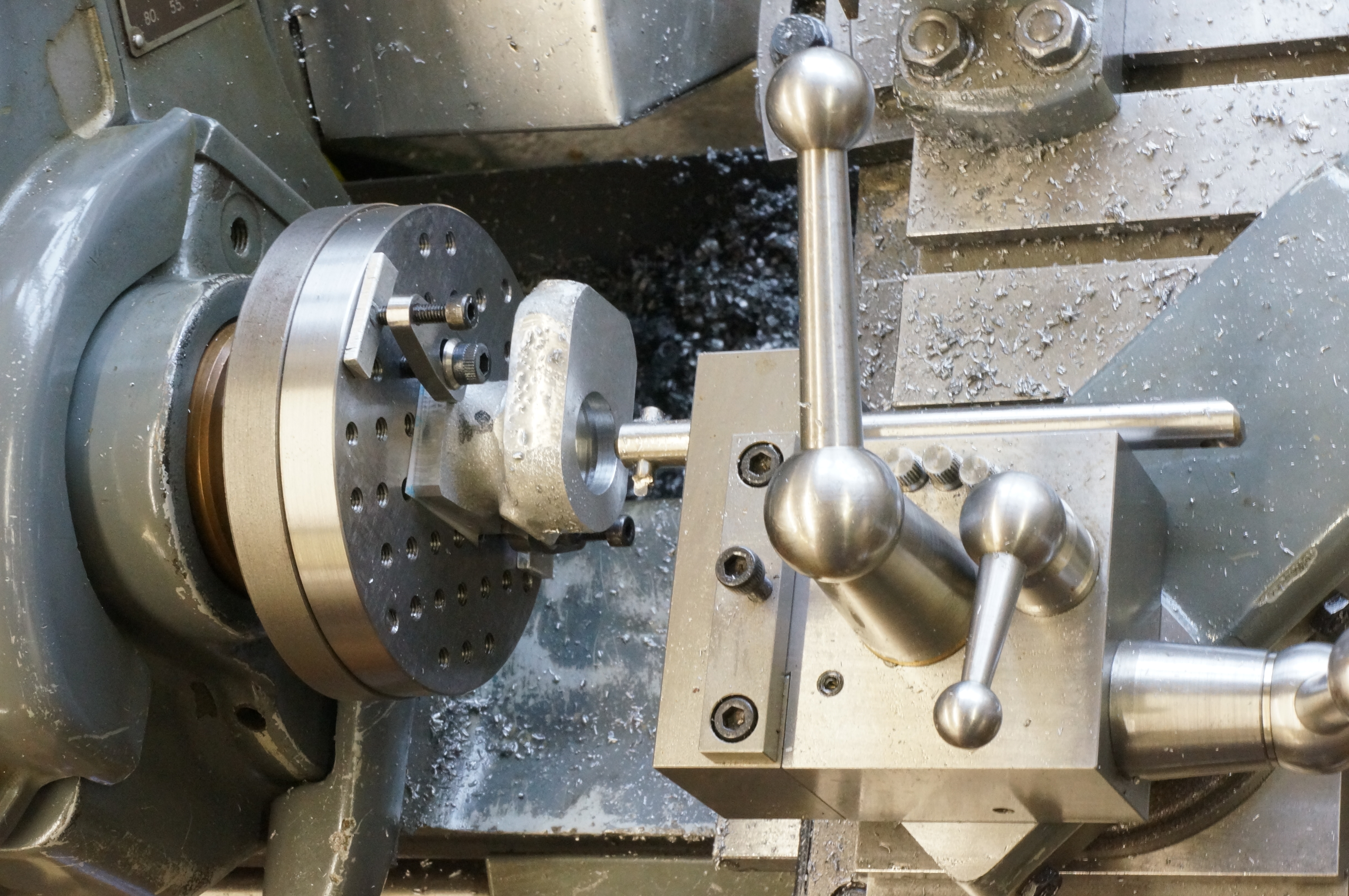
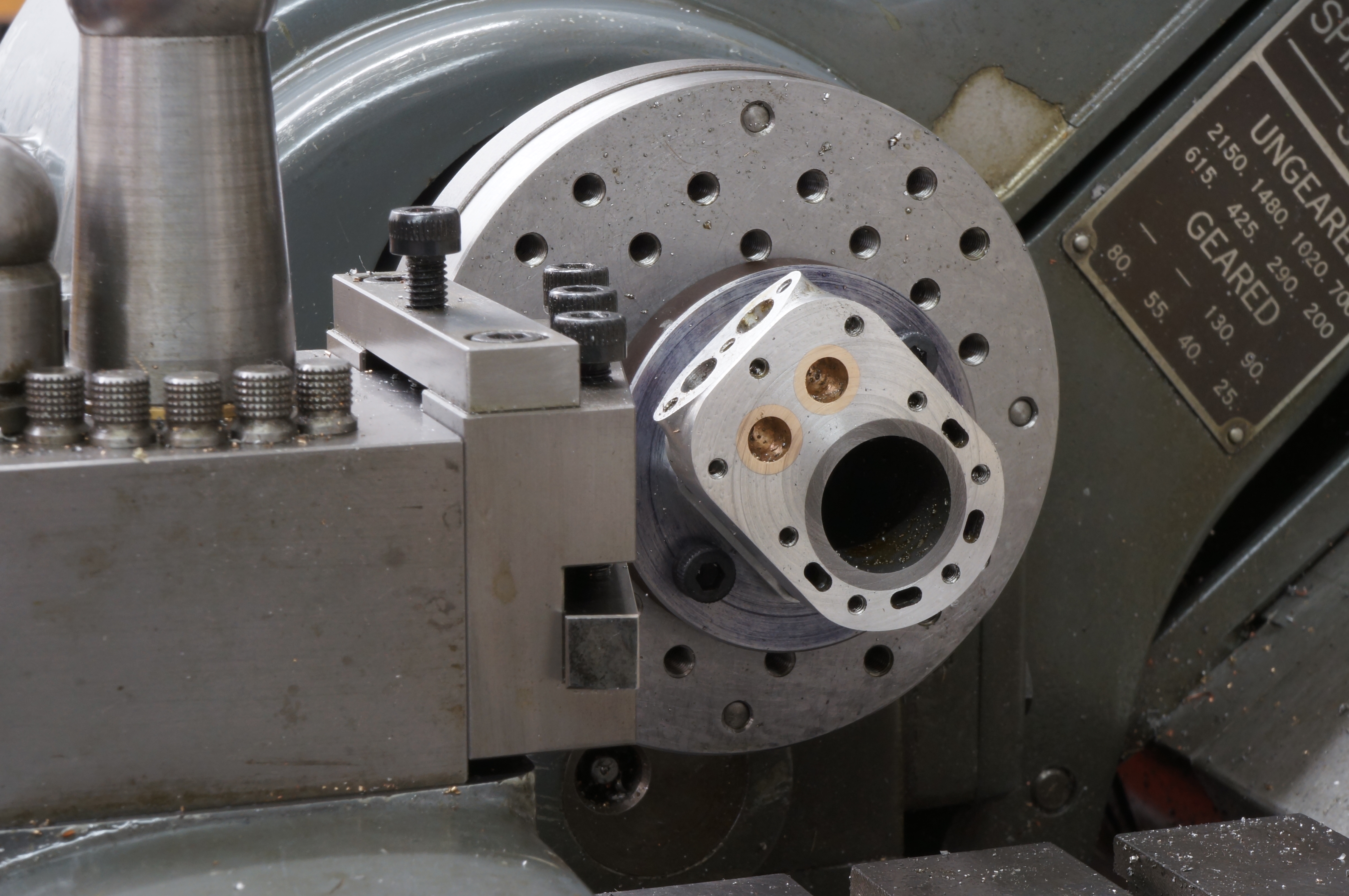
Because of the small footprint of the bolting flange, I decided to use my small faceplate for this set-up. Using a centre in the tailstock allows an initial position to be found quickly. After a bit of a fiddle I got the bore of No 2 cylinder running within 0.0005″. With the top-slide set at 45° for the sloping part, all the boring is done to dial readings on cross and top slide and leadscrew handwheel. This requires good notes on the whiteboard by the lathe, careful zero settings, remembering the directions for backlash, and keeping ones wits, especially allowing for the top face not being to finished size yet. First, the leadscrew dial is set to zero. Next, with the tool touching the face, the top-slide is zeroed, and finally, moving the saddle and cross-slide but not touching the topside, the tool is touched on the bore to set the cross-slide. Now with all dials zeroed the tool is set. The top slide is not touched until the last step of machining the transition slope, anything else would be too confusing.
The only difficulty with boring the recess for the shoulder of the liner is to measure the diameter accurately. I used a vernier, but measured over the tips with a micrometer.
No 1 cylinder was treated exactly the same. All cuts were taken at a modest 100 rpm (turning the VFD down to 25hz), using the same coolant as before. This produced an excellent finish.
Although I want to work on the water inlet flanges next, while the lathe was set up for turning I decided to make a centering spigot for milling the water passages on the rotary table. (5¾ hours)
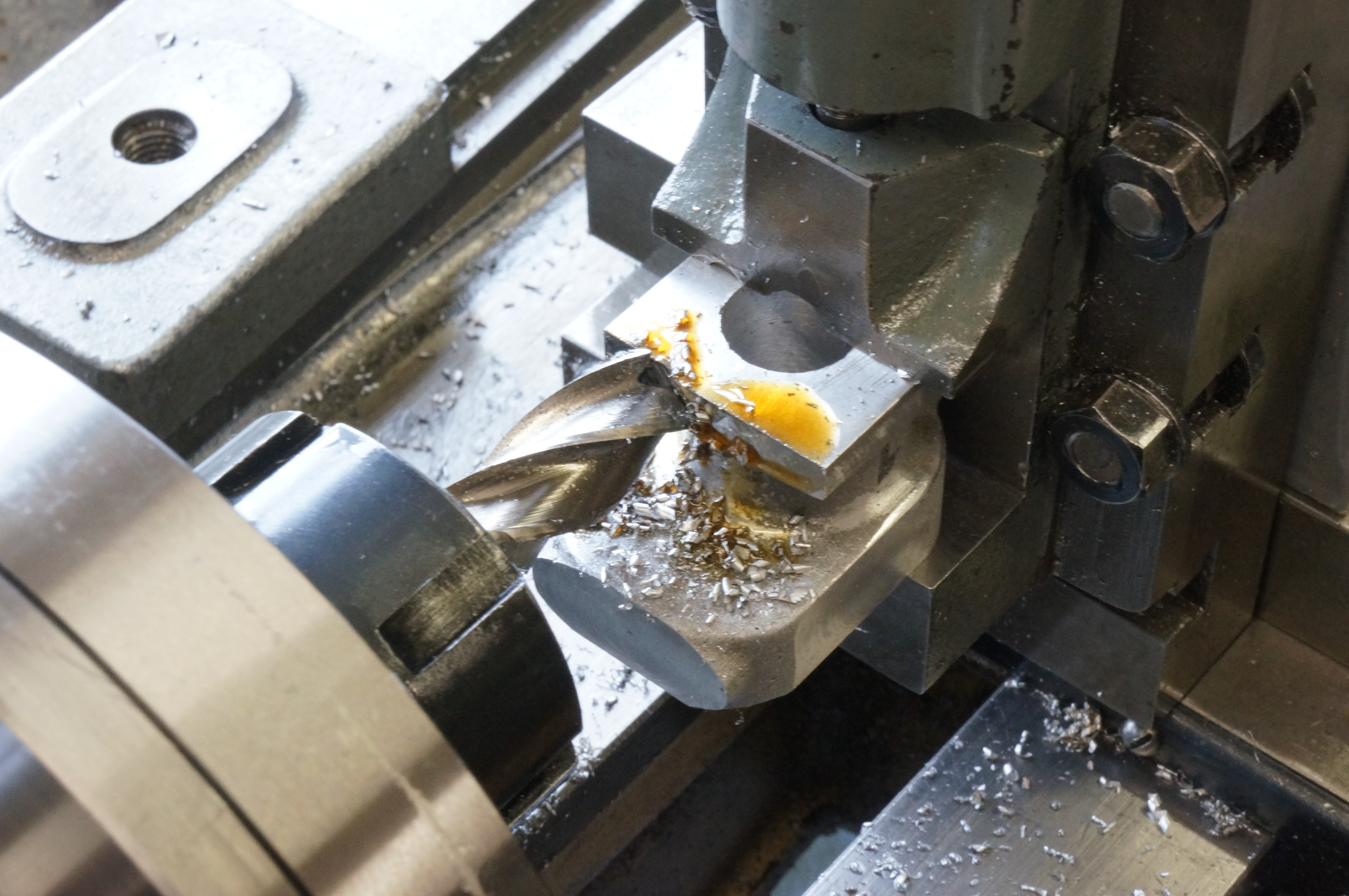
2013-04-14 - Water ways
Rather than 1⁄8″ diameter holes, I have decided to make 2.5mm wide slots. These narrower slots save a little of the scant radial space while providing slightly greater flow area. They can be kept just clear of the liner recess. The size is partly determined by the availability of a ball-nose end-mill with adequate reach.
With the locating spigot finished I set up for milling the water passages. I set the GHT rotary table square and clocked it on centre by the central hole, and zeroed the dials. With the rotary table locked at a 45° mark, I clamped the No 1 cylinder in place with its sides set vertical. I rotated the table 90° to the horizontal position and again locked it. I lifted the vertical slide 17⁄32″ for the pitch circle radius of the water passages, and backed the cross-slide out by 0.045″ for half the length of the slot (overshooting and winding back for the backlash, as all positions are taken on the infeed).
I started by using a No 1 centre-drill and drilling 2mm diameter to 21⁄64″ depth, running the lathe at top speed and 60hz on the VFD (yup, 'overclocking' a Myford). With the cross-slide wound in 0.090″ I drilled a second hole, and then worked between the two positions with a 2.5mm ball-nose cutter, taking about four cuts to finish the holes to the depth of 21⁄64″ (plus the 0.011″ finishing allowance), and then taking a final plunge at each end.
I machined the remaining three slots, rotating the table 60° between each, and repeated to process on No 2 cylinder. Where these passages emerge inside, some have not cleared to the top of the water space and most have an unsatisfactory thin edge. I think will need the services of a dentist to improve these.
Moving on to the water inlets, I need to take roughing cuts on the angled flange faces so that I can measure up and determine the final position for this feature. With the swivelling vertical slide set round at 60°, I took a cut to clean up the flange. It is always a bit tricky to determine a datum for angled cuts. In this case I chose the bottom edge of the bolting flange, using a feeler gauge under the cutter to get the setting, and then fed the saddle ¼″ from there. (6 hours)
.
2013-04-25 - Finishing the water inlet flanges
To minimise the amount of hand finishing I have to do on the cylinders, I want to turn as much of the outside of the barrel as possible. This means setting the water inlet flanges as high as the castings will comfortably allow. After doing a bit more filing to clean up the flange profiles, and measuring up the roughed-out flanges, I decide to take another 0.020″ off, and possibly a further 0.010″ if it looks right.
Working on No 2 cylinder first, I actually took another 0.027″ off the face, which agrees with my drawing. With No 1 done too, they look fine, and measuring to the top middle of each flange, they are within a gnat's of the same height, and the distance from the port face is about 4 thou different.
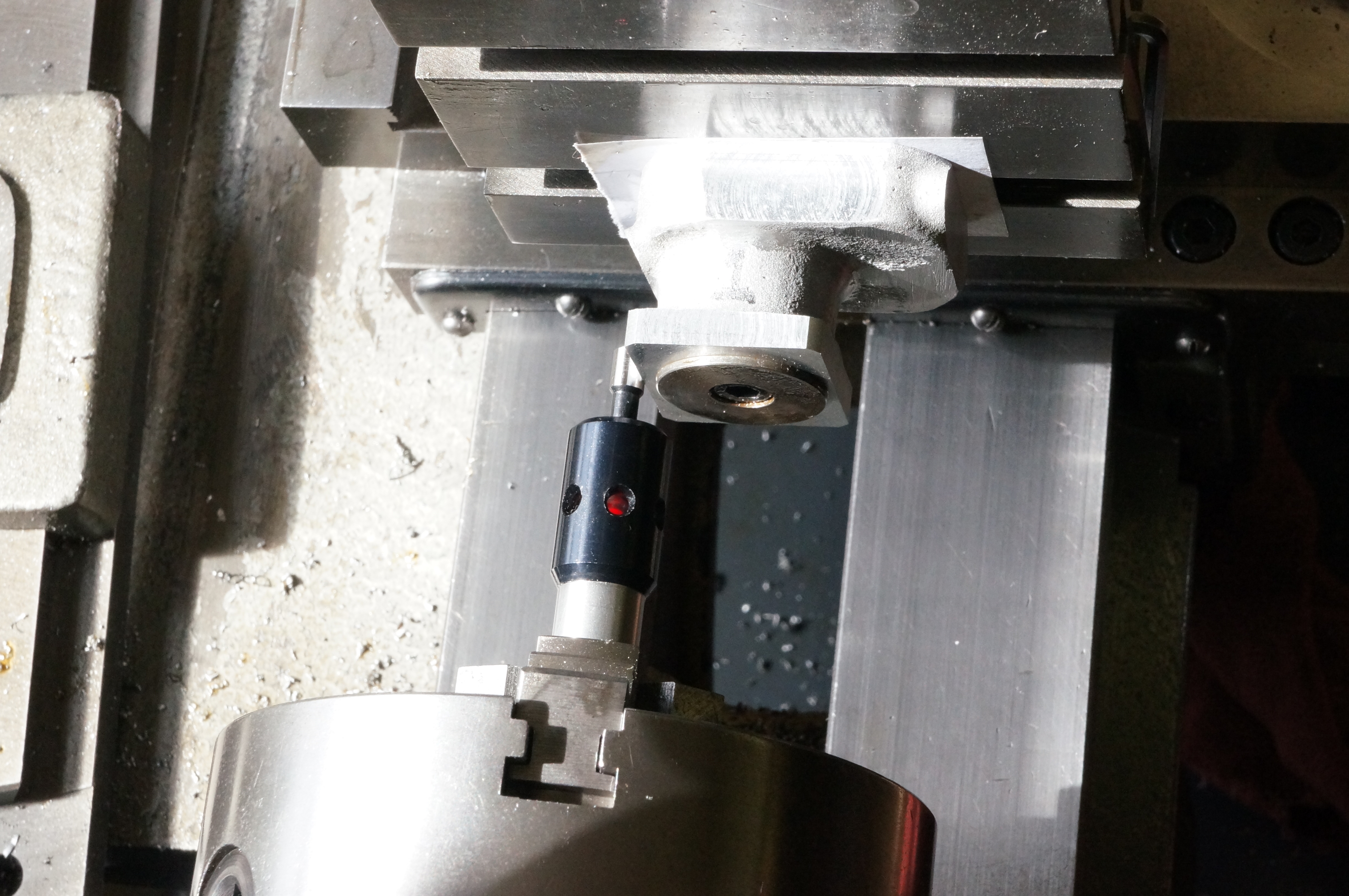
With these dimensions I adjourned to the computer to update the drawing and calculate a measurable dimension for the hole centreline. I could have used the surface plate to scribe a line at the right height, but the flange faces are finished surfaces and I did not want to mark them. Set up yet again on the slewed slide, I set my 'sticky pin' running true in the chuck and used my headband magnifier to line up the edge of the foot with the point of the pin. Now that I am starting to lose the close-focus ability that short sight gives, I find magnification increasingly necessary. It was then a simple matter of winding the cross-slide out, by the amount worked out for me by Autosketch, to get the centreline through the flange holes.
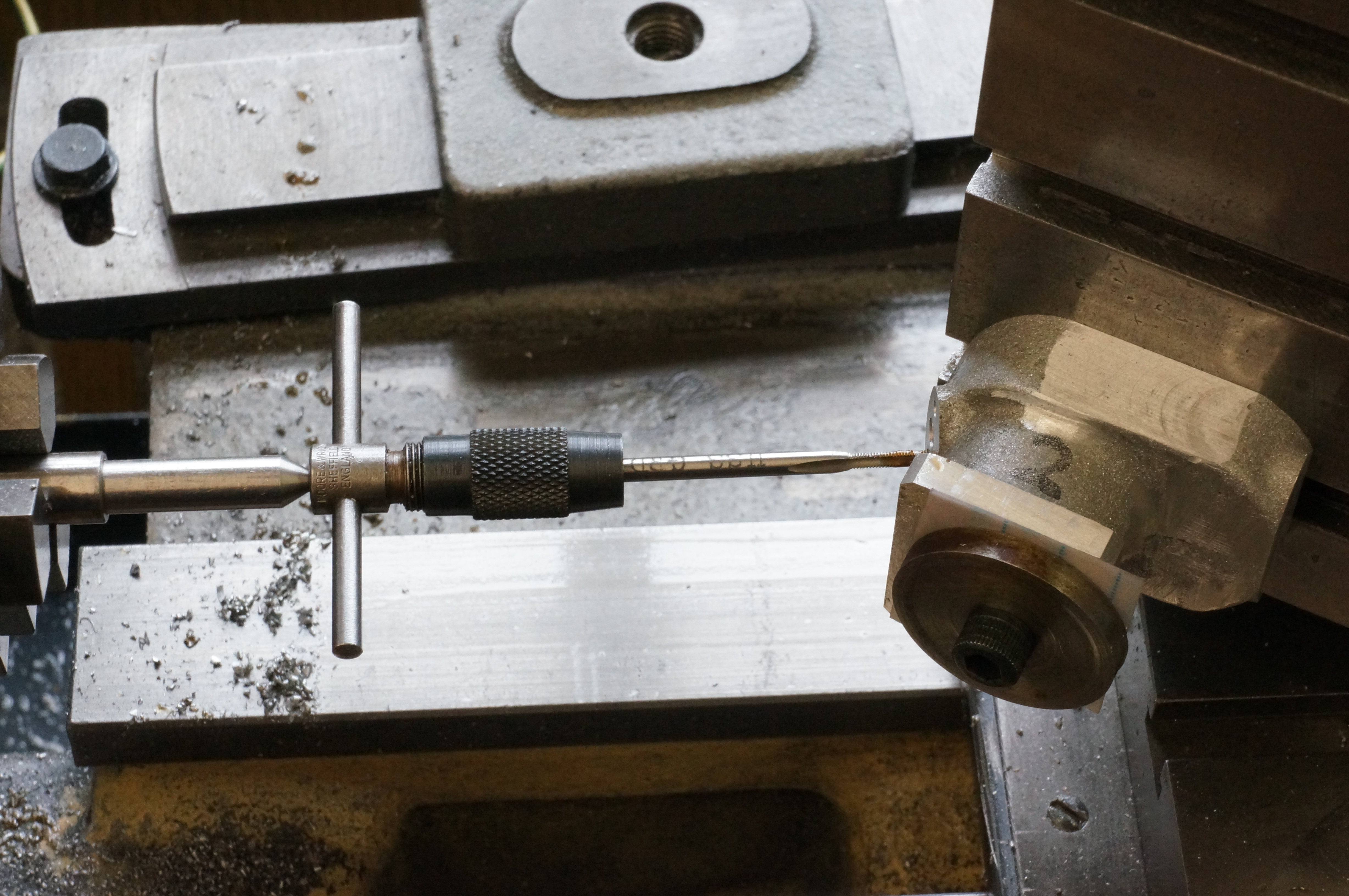
I drilled the stud holes 3⁄16″ deep, about as far as I could go without any risk of breaking through. I routinely tap 6-BA holes with the tap held in the 3-jaw chuck and using a mandrel handle, but for these 8-BA holes I thought that was a bit risky and used a tap wrench supported by a spring loaded plunger. The holes were just deep enough to get the desired seven turns of engagement. (5 hours)
2013-04-26 - Mounting & Valve Guide holes
Drilling the holes in the mounting flanges was straightforward once set up. My LED probe does not run true, so it either has to be adjusted with the Griptru chuck, or as I did in this case, try a few positions to minimise runout and then rotate to find a mid-point. In this case it was only a few thou out, but even so I moved it a quarter turn to get side and top positions. In working from the zero settings, I also needed to remember the each edge of the flange has an extra thou on for finishing. Drilled at 2.9 mm, the cylinders sit nicely on the crankcase studs but they are a shade off square so they will need opening out a bit more. Westbury says these should have a reasonable amount of clearance to allow the manifold to line the cylinders up. Incidentally, the washer with the recessed cap-head, used here to clamp the cylinder, has been in the special washers box for over 30 years. It was originally made for boring the arms of the Universal Pillar Tool.
With the casting reversed for the valve-guide holes, I worked both holes together, moving between them on the cross-slide dial. I drilled both holes out to 7mm, and took what I thought was a 10 thou roughing cut with the boring head, which unintentionally and confusingly resulted in reaming size holes of 0.307″ diameter. After reaming I tried a boring cut to make the counterbore for the valve seat shoulder, but decided a slot drill would do the job perfectly well, giving a consistent size and a sharp corner, which, unusually, I don't mind here. If the diameter is not exactly 3⁄8″, the seats can be made to fit. Doing the No 2 cylinder, I found the 7 mm drilled hole measured 0.287″ or about 12 thou oversize, which explained why I got a surprise with No 1. I will have to remember to investigate the drill bit. (4¾ hours)
2013-04-27 - Port holes

In a short session today I set up No 1 cylinder to drill the ports and manifold stud holes. It took a while to get the cylinder square. Sometimes it does, and sometimes it is easy, with no particular reason I can see. Today, holes centre drilled, drilled 6.25mm and finished with a 1/4″ drill, were actually undersize. An exact ¼″ ground pin would not go in the holes. After the valve guides are fitted, perhaps I should polish the ports!
I had time to drill and tap one of the stud holes. (1¼ hours)
2013-04-28 - More port holes
Today I drilled and tapped the remaining two stud holes in No 1 Cylinder, and then completed No 2, which clocked up square more easily this time.
Had a tidy up. Now it is time to bring the cylinder heads up to the same stage. (2 hours)
2013-06-22 - Flange and barrel
I used a convenient stub of brass to make a short, shouldered stub mandrel to carry the cylinders for turning the top face of the bolting flange, and as much of the barrel as possible. Starting with No 1 cylinder, I turned the flange to thickness and the barrel to 1.020″ diameter, then, changing to a right-hand tool, up to 39⁄64″ from the bottom, which marks the lowest point on the finished water inlet flange. Tools with suitable radii were used.
The No 2 casting was evidently smaller or not as well centred, as the first cuts, before I measured anything, took the diameter below that of No 1. Neither has fully cleaned up all the way round. Should I reduce No 1 to match No 2? Checking a few days later, No 2 is 1.009″ diameter. I decided that, as these surfaces will in the end be sand blasted anyway, the small discrepancy did not matter. (2¾ hours)
2013-09-13 - Profiling the water flanges
Trying out the template I completed earlier today, I started shaping the water inlet flange on No 2 cylinder, mainly with the Dremel. (¾ hour)
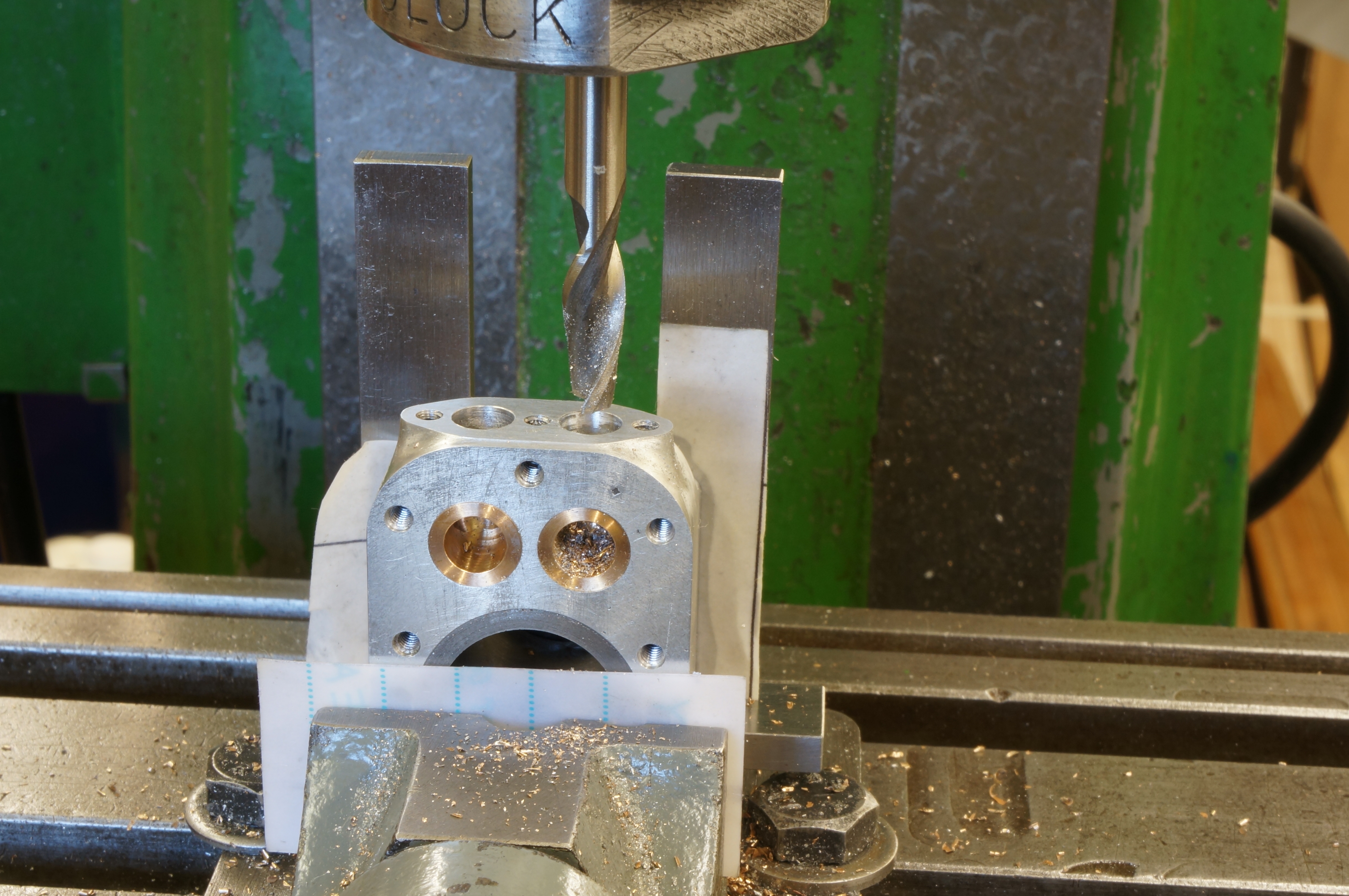
2014-03-28 - Drilling head bolt holes

After sharpening my 2.2mm drill using the newly made DAG Brown pattern Small Drill Sharpening Jig, I used the drilling jig in the pillar drill to produce the holes for the head bolts. I set the depth stop to bring the drill tip 1″ clear of the table, so that the holes would finish up the correct depth, however much has yet to be faced off the top surfaces of the cylinders. I found it necessary to take the ¼″ depth of the holes in 1⁄16″ pecks, to clear the chips out of the drilling bush, otherwise they would jam and start turning the bush, which in any case I had to hold in place with a finger nail. I drilled both cylinders to tapping size then changed drill and bush to make the little counterbores, again setting the drill point distance from the table.
After drilling the Cylinder Head Covers, I tapped the holes in No 1 Cylinder at the pillar tool. With the studs fitted finger-tight, both covers fit pretty easily, so the jig is doing a good job. (1¾ hours)
2014-03-29 - Tapping
In a short session today I tapped the holes in No 2 cylinder. (½ hour)
2014-04-05 - Fettling and profiling
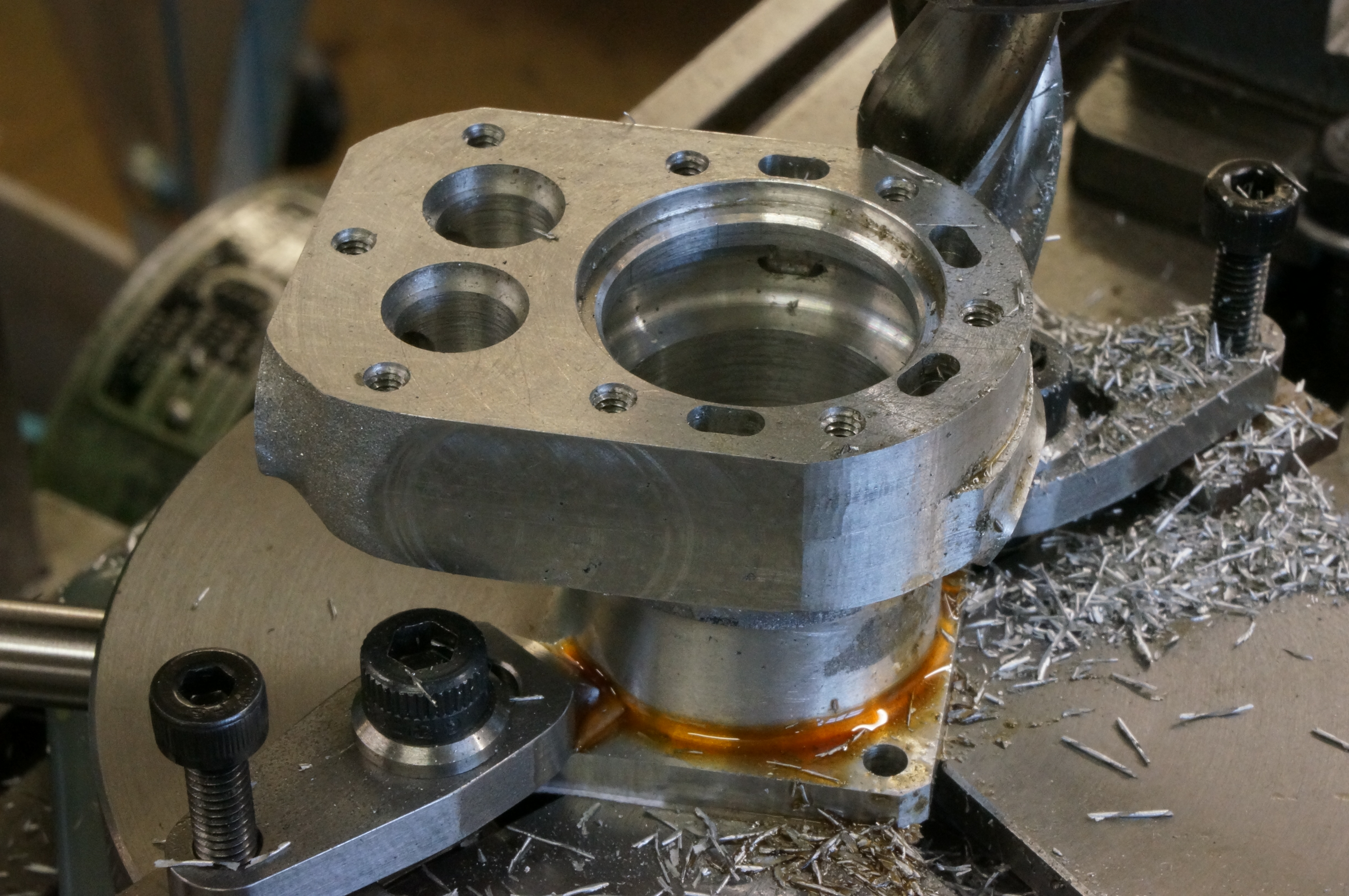
Using mainly a carbide burr in the Dremel, a round riffler and wet-or-dry paper I worked on the water flange profile on No 1 cylinder. It is not finished yet, but the general shape of the water jacket needs to be worked up first.
Having made some bushes to allow the small rotary table to be set up on the milling machine, I set up each of the cylinders and machined the bulk of the water jacket arc. The casting was located on the rotary table using the spigot made for cutting the water passages. I started with a 9⁄16″ end mill to remove the bulk. The asymmetry of the castings meant I was removing 55 thou at the most and just rubbing at the least, leaving a finishing allowance of 5 thou. At one point I narrowly avoided cutting into the water flange from the side. Using a ¼″ ball-nose cutter, I was able to take useful extra cuts to get closer to the final shape of the top of the water flange. I identified the cylinders with little punch dots on the bolting flange, on the hidden side. (5½ hours)
2014-04-13 - Fettling and Filing Buttons
Working on No 2 cylinder, now the general shape is close to finished size, I could make more progress with hand finishing the water inlet flange, and started work on the internal and external shoulder radii where the round barrel meets the water jacket.
I made some hardened 6BA filing buttons, two at ¼″ and two at 0.230″ diameter. The larger will be used for the cylinder bolting flanges, and the smaller for the cylinder covers, among other things. I also made a fitted screw to locate the buttons more accurately where 0.116″ diameter clearance holes have been used.
Using the larger filing buttons I finished the radii on No 2 cylinder bolting flange. (4 hours)
2014-04-26 - More Fettling
After getting the No 2 Cylinder Cover pretty much done, I finished the day with a bit more work on No 2 cylinder, on the underside of the water jacket. (½ hour)
2014-05-10 - Fettling & Radius Gauge
I continued with No 2 cylinder, but after an hour and a half of this close work I wanted a change of job and started work on a gauge for a 7⁄16″ blend radius for the join between the flat sides and the machined arc of the water jacket. I cut out and drilled the gauge blank and drilled & tapped an alloy block to mount the gauge on for milling.
While making the gauge, I knocked the RTD bottle of the mill table and broke the spout off the cap. There was an interlude while I made a replacement.
In the afternoon I did another ¾ hour's work on the cylinder, then completed the gauge, using the boring-and-facing head to machine the radius. With the gauge completed, I assembled the cylinder, head and cover and produced the blend radii on the assembly. (4¼ hours)
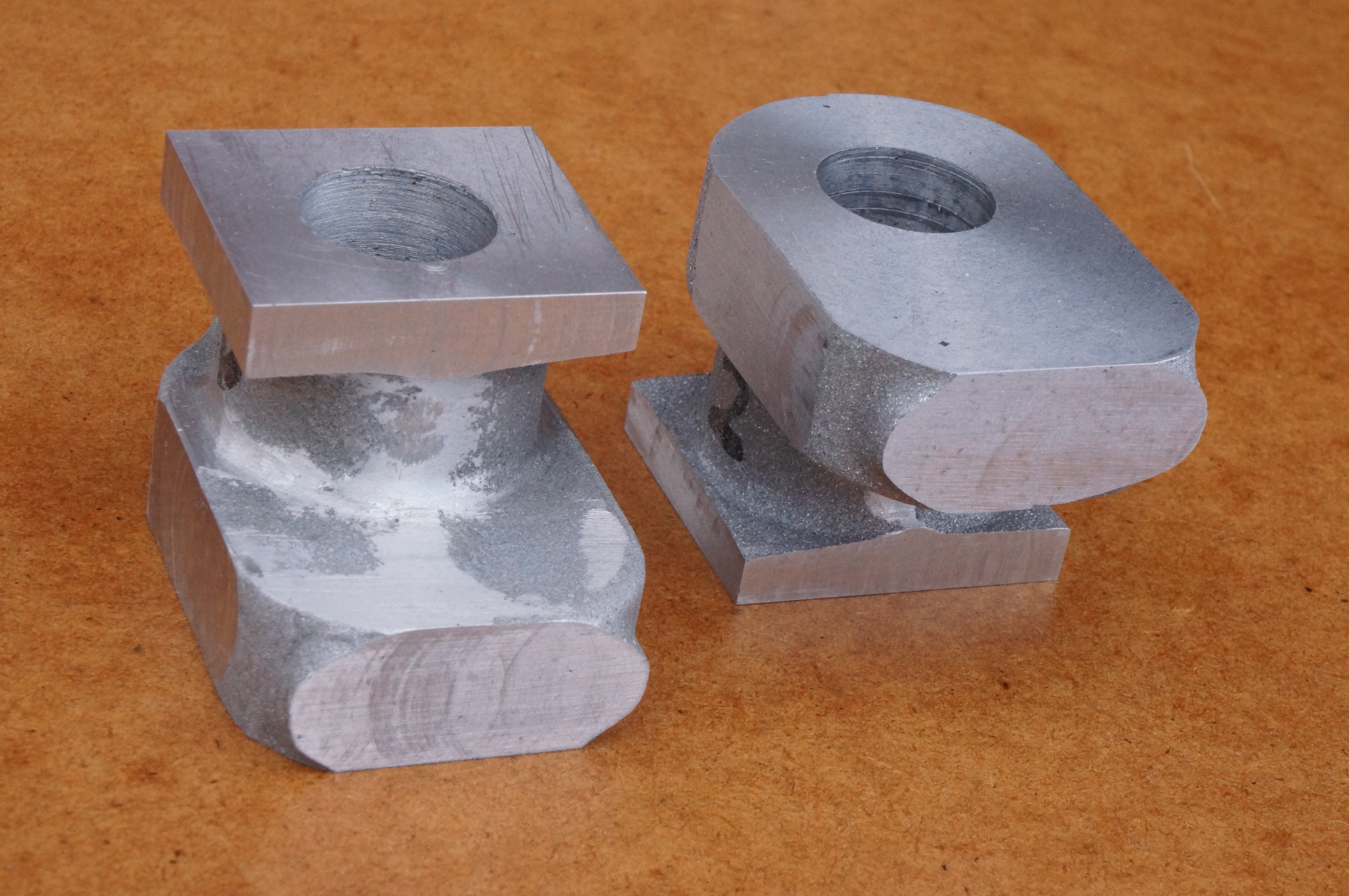
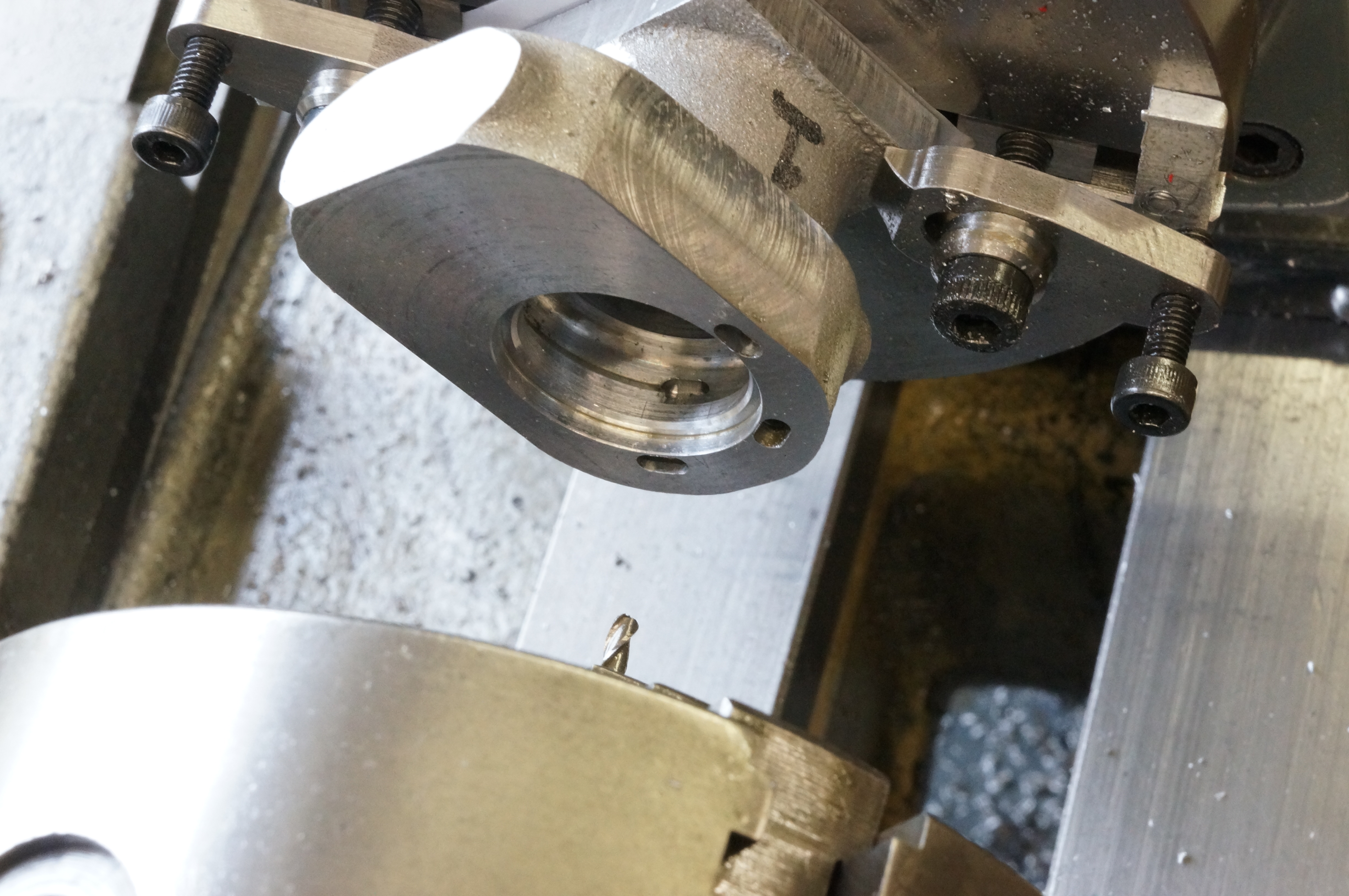
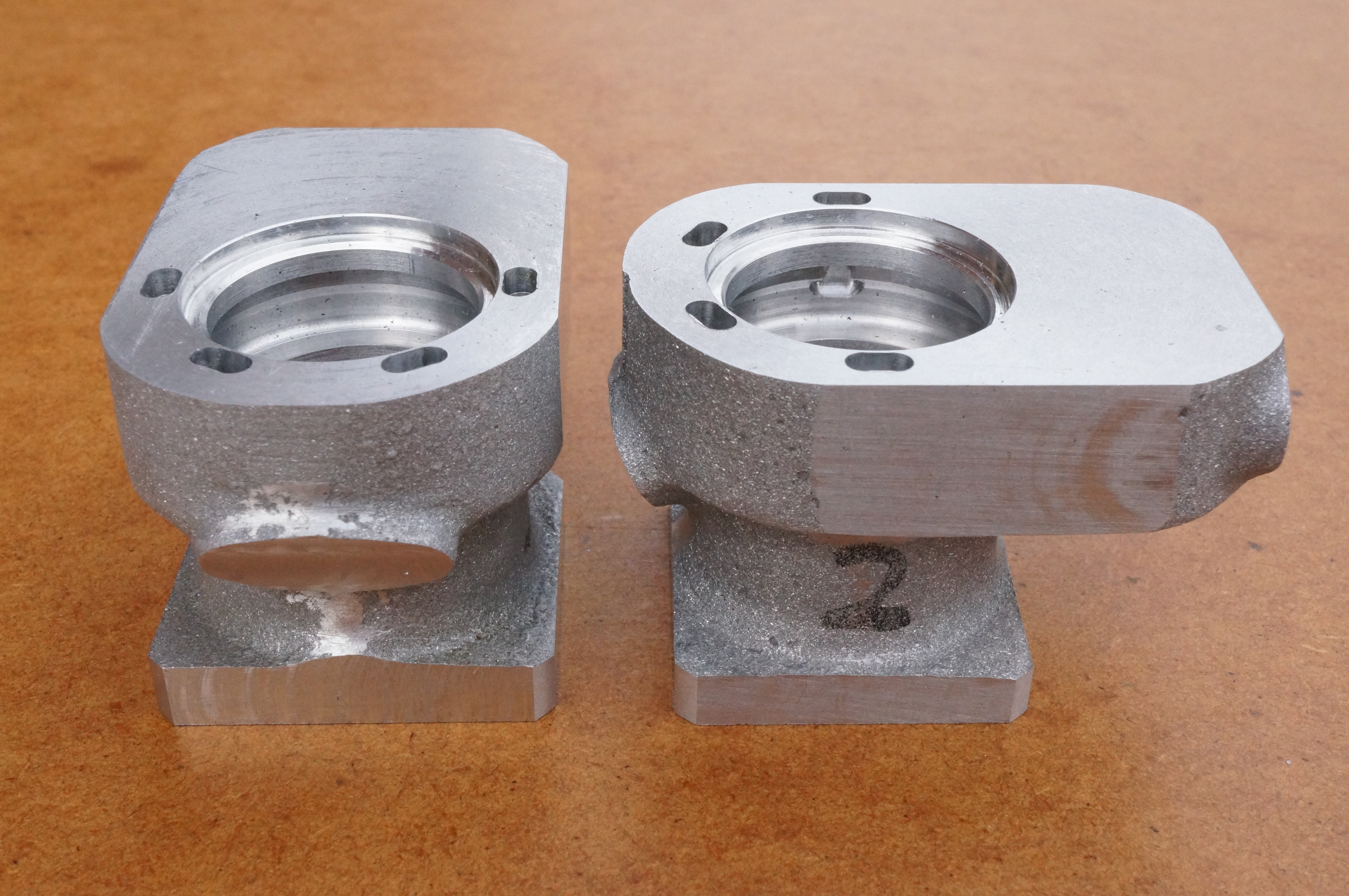
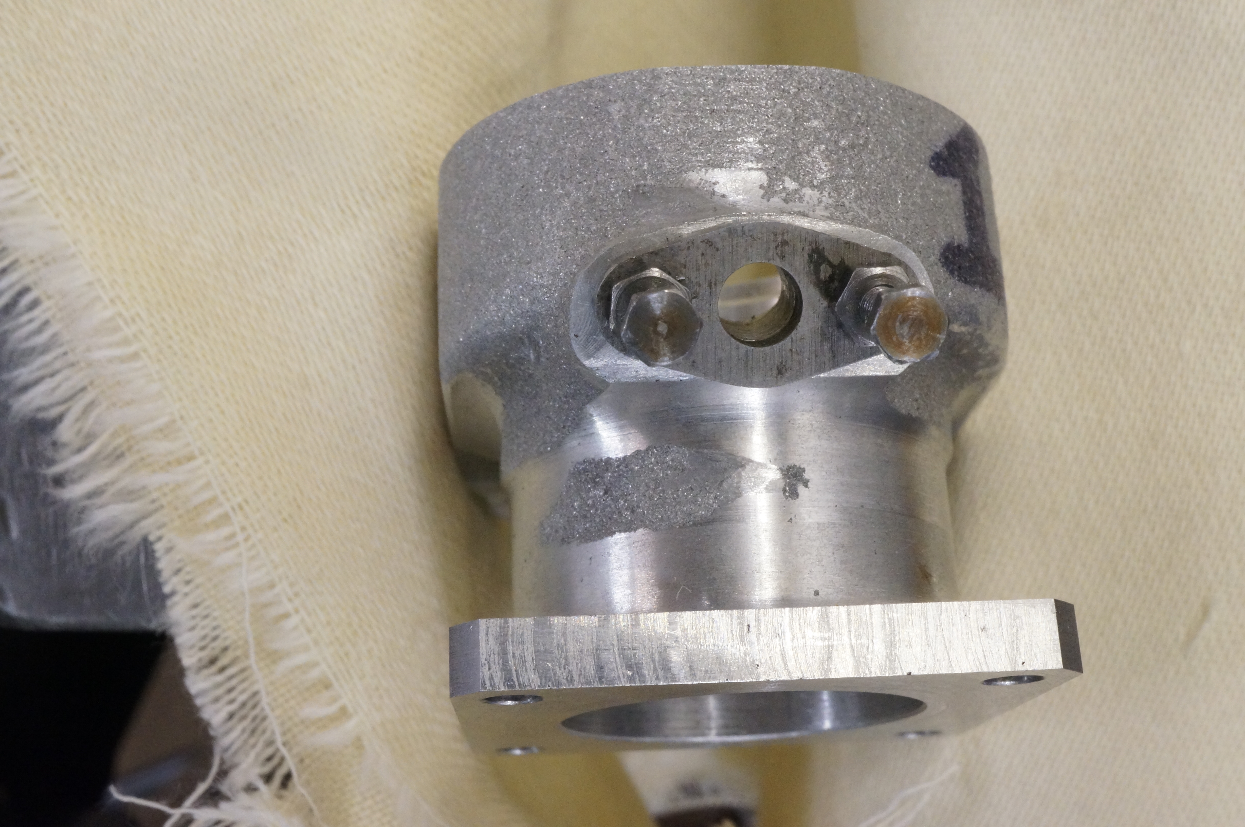
2014-05-13 - Still Fettling No 2 Cylinder
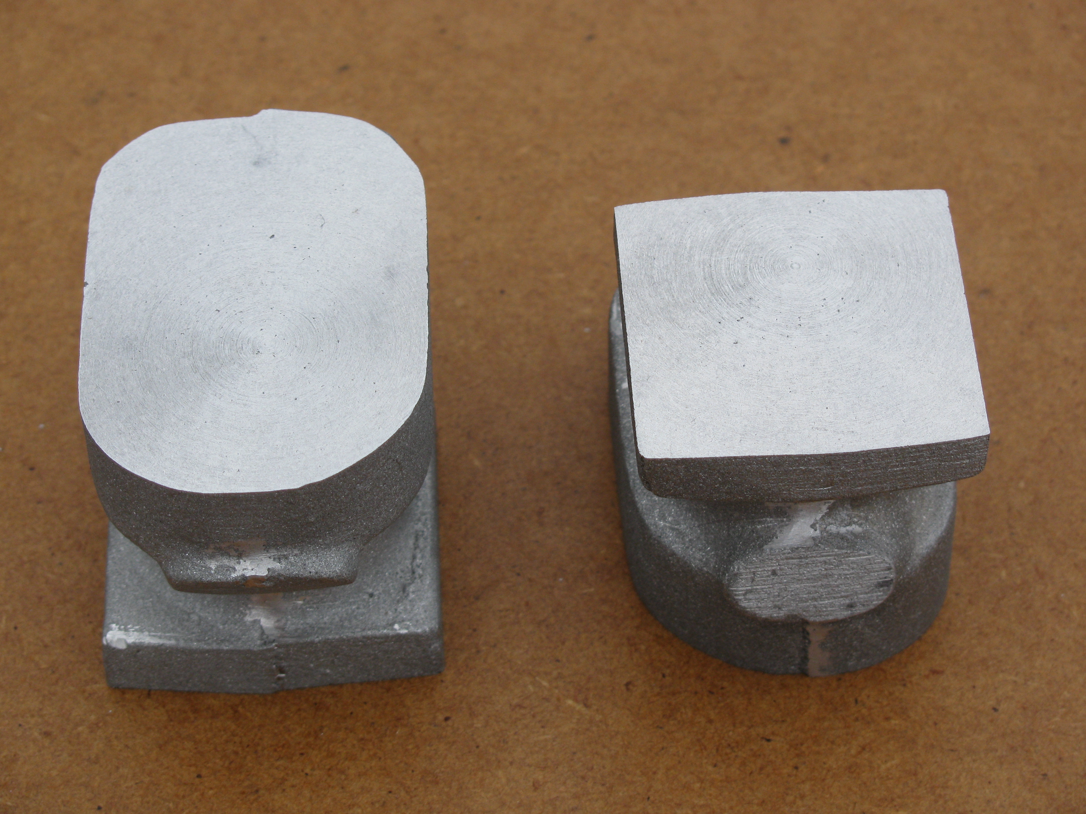
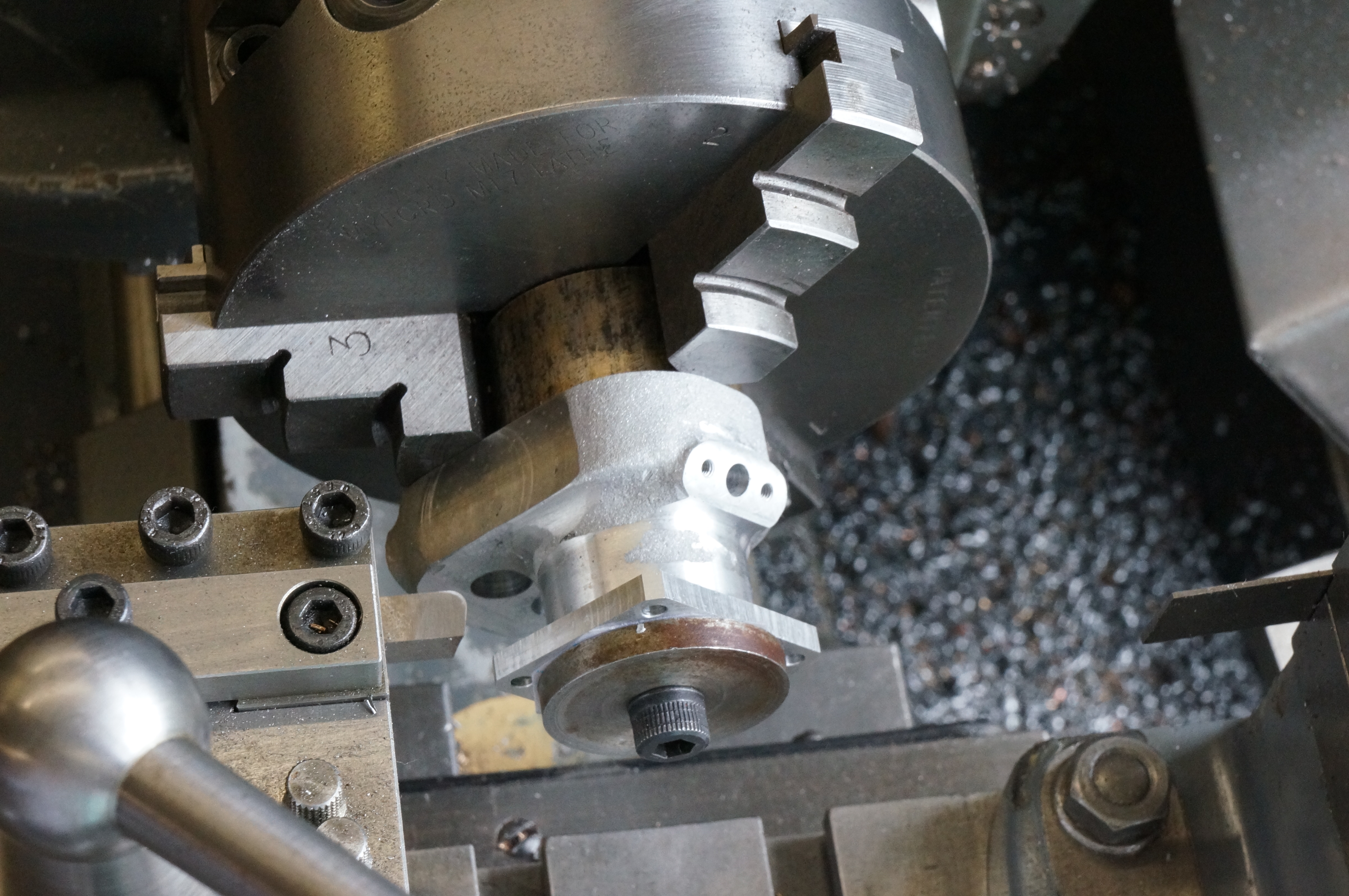
Today I continued with the cylinder, working mainly on the radius between the cylindrical barrel and the underside face of the water jacket. The lower parts of this cylinder now look done. The photo shows progress on fettling the No 2 cylinder assembly compared with the as yet untouched No 1. The area around the port face has yet to be worked on. (1¾ hours)
2014-05-20 - Making a Portface Template
As a break from working on the cylinder covers today, I cut a piece of 3⁄32″ gauge plate to make a profile template for sculpting the port flanges on the cylinders and milled it to width. (1 hour)
2014-05-24 - Working on the template
I put the four holes in the template and cut one of the bevels. After realising just what it was that was wrong, and re-machining the finished width, I re-cut the first bevel and then the others. Using filing buttons made previously, I filed the small radii at the ends. Finally, I made a pair of 7⁄16″ diameter buttons for the blend radii. These were mild steel, and left soft, as they did not have a difficult job. (3¼ Hours)
2014-05-27 - Completing the template
Today I finished the template by filing the large radii, and hardening it. I then used it to roughly shape the portface on No 1 cylinder. (1 hour)
2014-05-28 - Shaping No 2 portface
Working on No the 2 cylinder assembly, I found I needed to use a full set of cylinder head studs to ensure accurate registration of the parts. I used masking tape to protect the already finished surfaces. After an hour and a half of intense work I needed something else and moved back to consider the unresolved con-rod little ends. (1½ hours)
2014-05-30 - Finishing No 2 portface
In between working on little ends, I completed cosmetic work round the portface of No 2 cylinder. (1¾ hours)
2014-07-17 - Fettling No 1 cylinder
Intervening jobs have been: finally achieving success with the little-end bores, and making a pipe bender so that I can tackle the coolant pipes. I finished it earlier today. I finished the day by working with the Dremel on the radius between the lower cylindrical part and the underside of the water jacket. (1 hour)
2014-07-18 - More Fettling
Today I worked on the flanges, round the water inlet to start with, and later round the port face and corner shoulder, getting one side largely done. (2¼ hours)
2014-07-24 - More Fettling
After another necessary diversion, this time to finish turn the cylinder liners, this morning I worked on the underside of the water flange and its blending into the water jacket and barrel. (1 hour)
2014-07-26 - More Fettling
More sculpting work today. No 1 cylinder is coming on, but there is still a way to go yet. I finished the day by cleaning down the lathe and mill. (2½ hours)
2014-08-04 - More Fettling
I continued work on the port face and shoulders this morning. The diversionary job at present is coolant flanges. (1 hour)
2014-08-08 - More Fettling
After today the port face is pretty much done. I moved back to the radii at the top and bottom of the cylindrical barrel, and put the radii on the corners of the bolting flange. (2 hours)
2014-08-22 - More Fettling
More work done on the radius under the jacket, mostly round the water inlet flange. (1¾ hour)
2014-09-12 - More Fettling
Work today was initially hampered by my being unable to find my round riffler file. I spent an hour looking for it, then gave up and tried working without, but found it really indispensable for working round an internal corner radius. I eventually discovered it in the bottom drawer of the toolmakers cabinet (a drawer exclusively reserved for DTI's and other setting-up aids). I pretty much finished the radius and moved on to the exterior of the water jacket. (3¼ hour)
2014-09-13 - More Fettling
With some more work today, mainly refining the blend under the water inlet flange, No 1 cylinder is at last finally fettled, I think.
There are sharp edges internally where the vertical water passages cut through into the annular water space round the liner. They are difficult to get at, but I was able to do some trimming with the point of a riffler, being very careful not to scratch the machined surfaces. Working on both cylinders.
I also tried cleaning the cylinders using an ultrasonic bath. The water ended up dirtier than it started but some larger pieces of swarf were not shifted. Hot water, detergent and brushes seem to be at least as good. (3¾ hours)
2014-12-27 - Fitting the Valve Guides
With the liners in, and finish lapped yesterday, the next job is to fit the valve guides. All parts were cleaned with Loctite 7063, and the guides fixed in with Loctite 648 as before, allowed to cure, and any remaining liquid cleaned off.
Clocking up No 1 cylinder for drilling the port through is not easy because the the port drilled in the cylinder is rather rough. I started with the inlet side, using a centre drill, a 5mm drill, and finishing with a ¼″ ball-nosed slot drill. Because of the offset cutting forces the cutter has wandered, making the hole oval, to a maximum of about 0.012″ oversize. This is irritating but not a disaster. I need to think of a better way to do the other holes.
While pondering, I deburred the hole. This was not easy because it is difficult to get at, the bronze is tough, and on no account can the valve seat or guide bore be damaged.
I faced a slice of 2¼″ mild steel bar to about 3⁄8″ to make a mounting plate for the next job, which will be facing off the top of the assembly.
Westbury notes that the cylinders need to have a little play on the mounting studs on the crankcase, to allow them to bolt up tight to the manfold. Both cylinders needed one hole easing out to 3.1 mm before they would sit home with a little play detectable on the studs. Coincidentally it was the same hole on both cylinders.
Going back to the port holes in the valve guides, I concluded there was really nothing wrong with the set-up. I cut No 1 exhaust port, but this time put 7⁄32″ and ¼″ standard slot drills down the hole before using the ball-nosed one to finish to depth. This is still a one-sided cut because it is forming a radiused bend in the valve guide at the bottom and it has still pulled to the side, but nothing like as much. (5 hours)
2015-01-09 - Making the mounting plate
A brief spell in the shop today, marking out the mounting plate. (½ hour)
2015-01-14 - Drilling No.2 port holes
I completed the mounting plate today by boring it to take the projecting bottom ends of the cylinder liners and drilling a tapping the bolt holes.
I then set up No 2 cylinder for the port drilling operation, and did the exhaust port. This look a better job, so far. (3½ hours)
2015-01-15 - Final facing
The inlet port, however, was a long way from round and difficult to clock up. I filed a shade off the diameter of a stub of ¼″ brass rod until it would fit in the hole, and then clocked from that. I soon got it to 0.01mm TIR, and drilled and milled the port as before. Deburring again took time and care.
With No.1 cylinder mounted on the small faceplate using the prepared plate, and a freshly honed tool, I faced the liner and valve cages flush, and then took cuts of 0.006″ & 0.002″ to finish, noting the reading on the topslide dial. Remembering to leave the saddle locked, I swapped cylinders on the jig plate and faced No.2, to the same setting for the final cut.
After cleaning up and blowing the water spaces through with air, I checked the heights of the cylinders. They are within 0.0005″, are a trace higher on the water inlet side (which will, I hope, tend to be corrected when lapping as the area is less), and have a lapping allowance on the face of about 0.002″. (3½ hours)
2015-02-16 - Making bits for bead blasting
In preparation for bead blasting the cylinder assemblies, I made a plug for the waterway flange, and sleeves, washers and 8BA temporary studs to protect the valve guides. (2¾ hours)
2015-02-20 - More bits for bead blasting
With a suitable plug fitted its the central hole, the mounting plate, used for the final facing operation, will serve to blank the bottom face. I turned up a disc to fit and Loctited it in place. I made a blanking plate for the water inlet flange, and started cutting down 6BA cap-heads for bolting everything together. (2 hours)
Everything is now ready for bead blasting.
.