
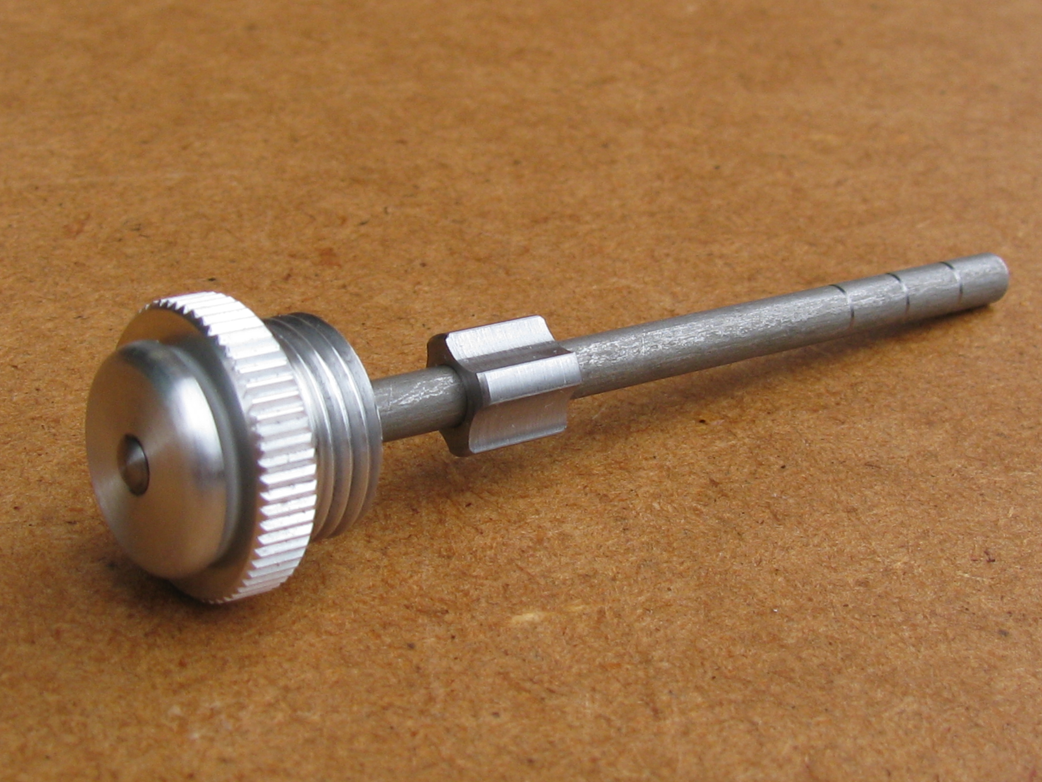
Oil Filler
I have modified the design of the oil filler arrangements slightly, partly to accommodate the difficulties found with the crankcase casting, and partly to make it a less prominent feature. A length of ¾″ dural (or similar) bar is supplied in the kit that is sufficient for the connecting rods and the filler parts, and a piece of 1⁄8″ steel, presumably for the dipstick. This simple little job actually consists of six parts, some of which are quite fiddly.
2011-07-23 – Filler Tube
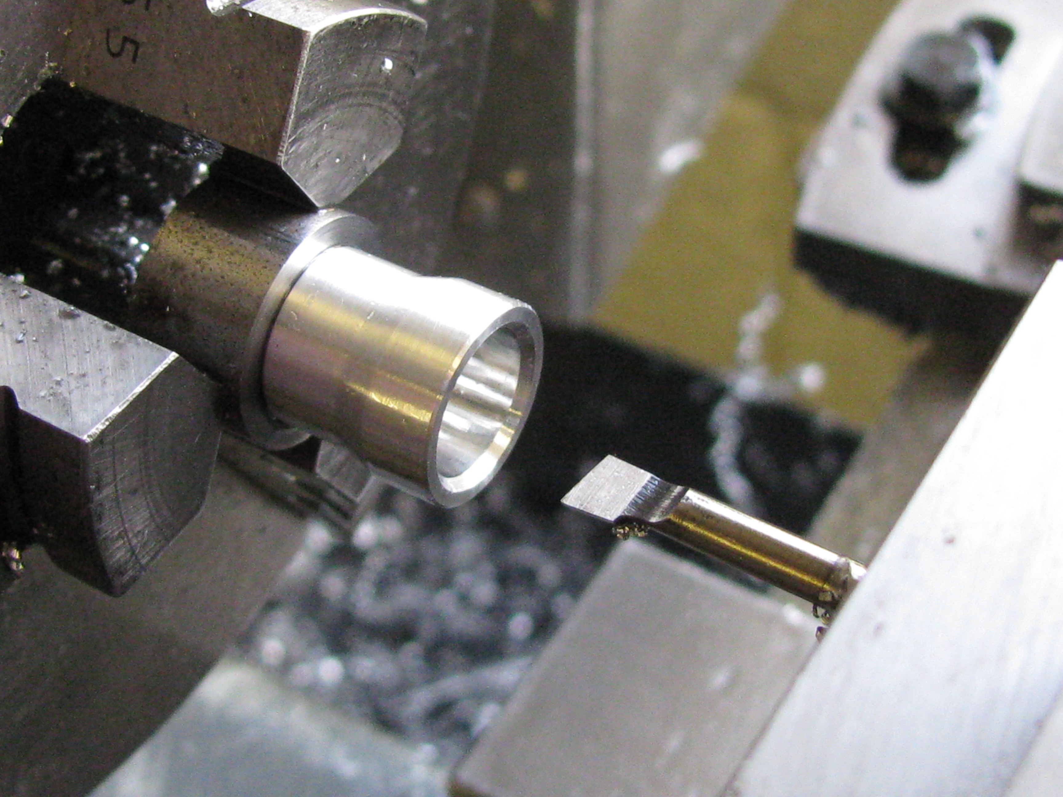
I parted off a piece long enough for the filler tube, breather plug and cap, and turned the exterior of the filler tube. To get the correct lengths and precise transitions between the parallel and tapered portions I first turned the larger diameter with a self-acting feed and then set the top-slide to the required 17° angle, and used the leadscrew handwheel to cut the parallel part to length, switching to the topslide for the taper. For this kind of job it is useful to have a whiteboard fixed up by the lathe for noting dial readings and the like. I blended the surfaces lightly with a strip of 800 grit paper. I cut the thread, using a hand chaser as a machine chaser for the last few thou, as I usually do. At 1½ thou over 3⁄8″ it was the desired tight fit in the crankcase. After parting off, I made a chucking bush to fit. I had to put some side pressure on the tap to enlarge the thread enough to be able to screw the tube easily fully home. I faced the tube to length, drilled and reamed the through hole and then opened it out, machining the tapered section as just described for the exterior. (3½ hours)
2011-07-30 – Tube, Plug, Cap & Diaphragm
To finish the filler tube, I screwcut the 7⁄16″ thread for the cap, finishing it with a plug tap. It was now pretty tight in the chucking bush. With a jubilee-clip over card softening it would not come out with finger force, so I put the lot in the freezer for half an hour, and the differential expansion worked a treat.

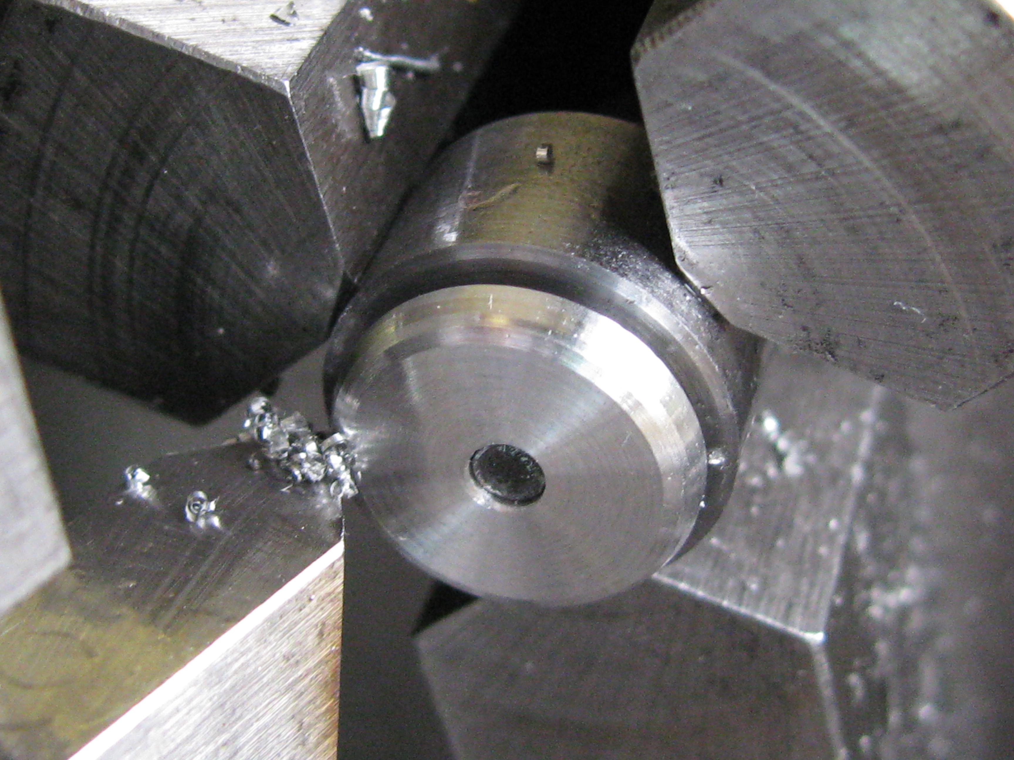
Working on the breather plug next, I set up the remainder of the length of bar using a shallow step in the soft jaws as there was very little length to grip. I turned the OD and screwcut the thread, a little bit sloppier than I intended, but this one does not want to be a tight fit. At this setting, I drilled the 6BA tapping size hole and counterbore for the dipstick. Using the dividing head mounted at the back of the lathe spindle, and my saddle traverse lever, I cut the "knurling" by shaping 60 grooves 10 thou deep in two passes, with a 90° point tool clamped on its side. With the dividing head transferred to the saddle and the chuck and job mounted on it, I drilled the breather holes. As designed, these holes are set on a 5⁄16″ pitch circle, but as this puts the holes a nominal 5 thou from the roots of the threads, I had drawn mine at 9⁄32″. This may not have been a good idea.
One problem with using the soft chuck jaws was that I could not get the parting tool in without fouling the base of the back toolpost, so parting had to be done as a second operation. I put the chucking bush with the 3⁄8″ thread back in the chuck, standard jaws, trued the face, opened it out to 7⁄16″ gas thread, put the plug in, parted the disc off for the breather cap, and faced and chamfered the plug and tapped the central hole.
Using a chucking piece with a 6BA bolt in the centre, I machined both sides of the cap. As usual I formed the radius by chamfering to calculated depths at 45°, 22½°, and 67½°, and then finishing with a file and fine wet-or-dry paper.
I made several diaphragms from plastic shim, first drilling a centre hole while sandwiched between two bits of MDF, and then, still using the 6BA chucking piece, turning the OD with the shim clamped under a full diameter washer. I found that 0.0075″ and 0.004″ thick diaphragms were too stiff to be able to blow through, but 0.002″ was too floppy to form a seal. A piece of thin leather was no good either. More experimentation needed. (5¾ hours)
2011-08-06 – Finishing the Dipstick
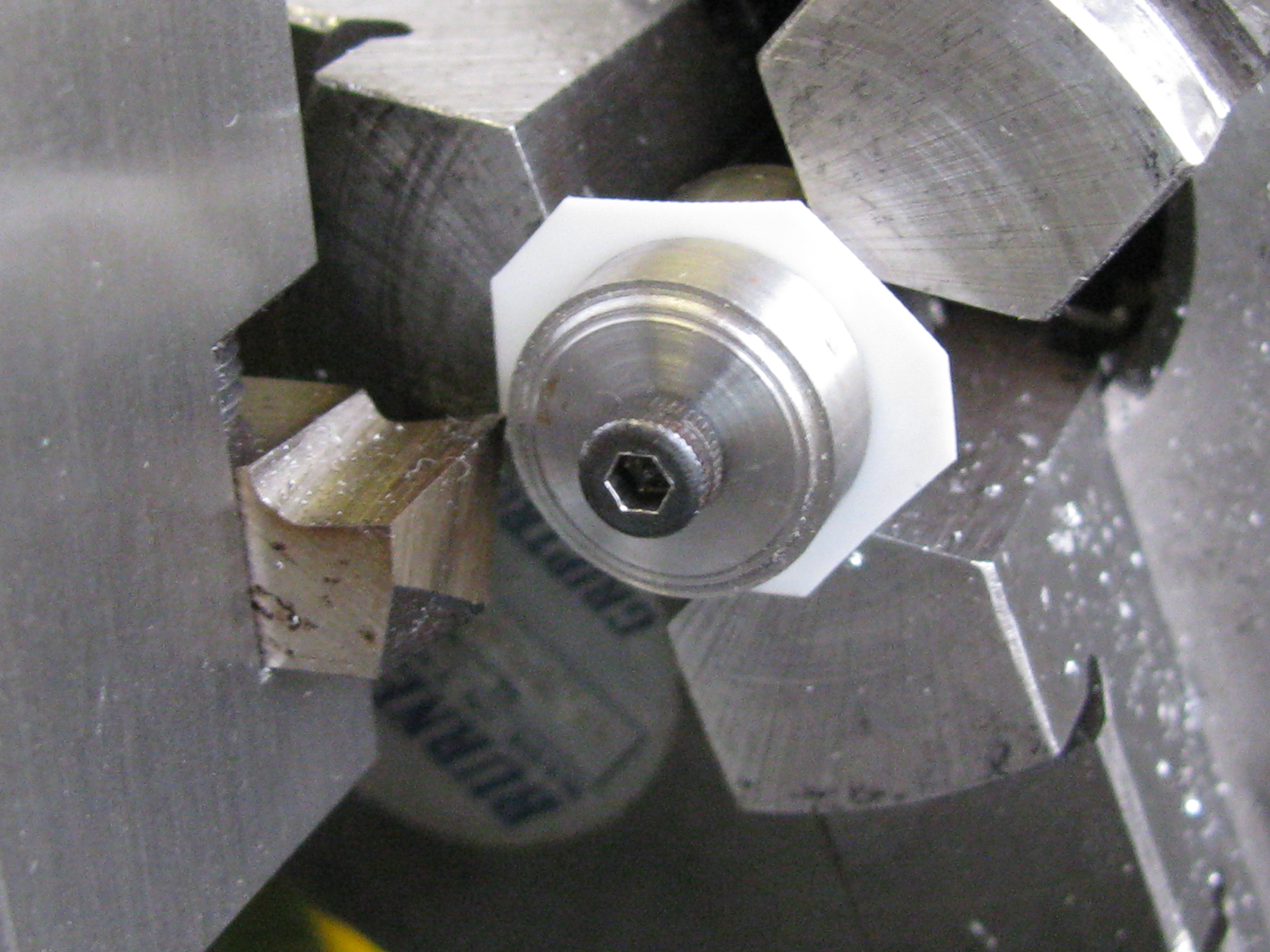
Thinking about the job during the intervening week, I decided that there is no harm in trying a valve that is loose, rather than a diaphragm clamped under the cap. The breather holes in the cap provide a very small surface area for the crankcase pressure to act on, and the valve wants to open at the lowest possible positive pressure so that the crankcase is mostly at a slight vacuum, to help keep the oil in, so it needs to open easily. As there is not much radial distance between the breather holes and the spigot on the cap, I turned the spigot down to 11⁄64″ diameter. I drilled a 4.8mm hole in a piece of 0.0075″ plastic shim, and having found the right toolholder, hiding in plain sight as usual, turned a 3⁄16″ diameter register, 0.005″ high, on the chucking piece to clamp the shim to, and turned it 13⁄32″ diameter. This loose valve ring seems to work nicely.
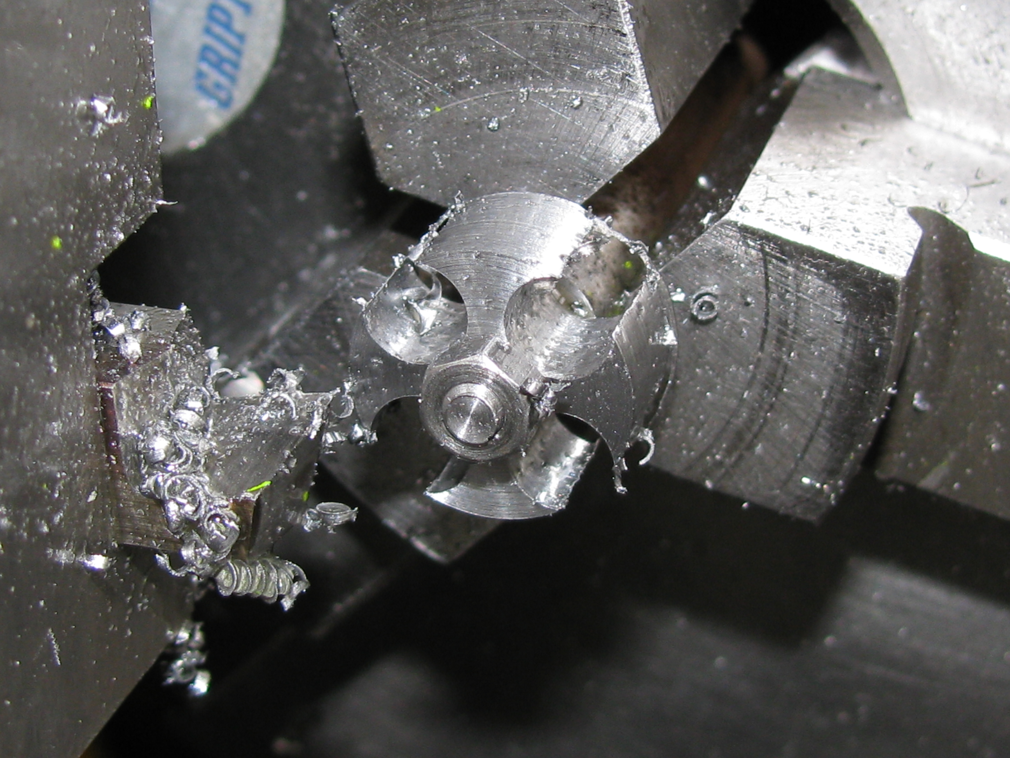
To make the locating spider I faced a piece of 5⁄8″ steel bar both sides to length and drilled and reamed the central 1⁄8″ hole. With the chuck transferred to the dividing head, I drilled, and for a smooth finish rather than accurate size, reamed four 3⁄16″ holes to form the air passages. I made a stub mandrel to hold the spider for turning the OD. In spite of the interrupted cut, the 6BA thread was sufficient to hold the part. After turning to a fairly easy fit in the breather tube I chamfered the ends and very lightly stoned the edges.
I turned and threaded the top end of the dipstick slightly over length, and assembled the plug and cap to find the exact length needed. After adjusting the length and filing and polishing a domed end I parted off at the other end, faced to length, put a radius on the corner and cut the three indicator grooves with a v-point tool. After cleaning the parts the job was completed by Loctiting the spider on the dipstick, just taking care that it did not move from the right position while curing. (4¼ hours)
The piece of rod supplied for the dipstick had a rather rough surface which I left alone as Westbury suggests some sort of texture. Actually I think the oil level might well show up better on a polished surface.
.
Studs and Washers
The fifty-six 6-BA studs for the engine require some 4 feet of 0.110″ rod. As this has to be turned down from 1⁄8″ material, another piece of tooling on the long-term list finally needed making. It took a good day's work (over three afternoons) to produce a Bush Steady. This serves the same function as a normal two-point travelling steady, but has a bearing bush bored in-situ to take the diameter of the stock. Mine is different from others I have seen in that the post is offset towards the headstock to accommodate quick-change tooling.
2012-11-03 – Making a start
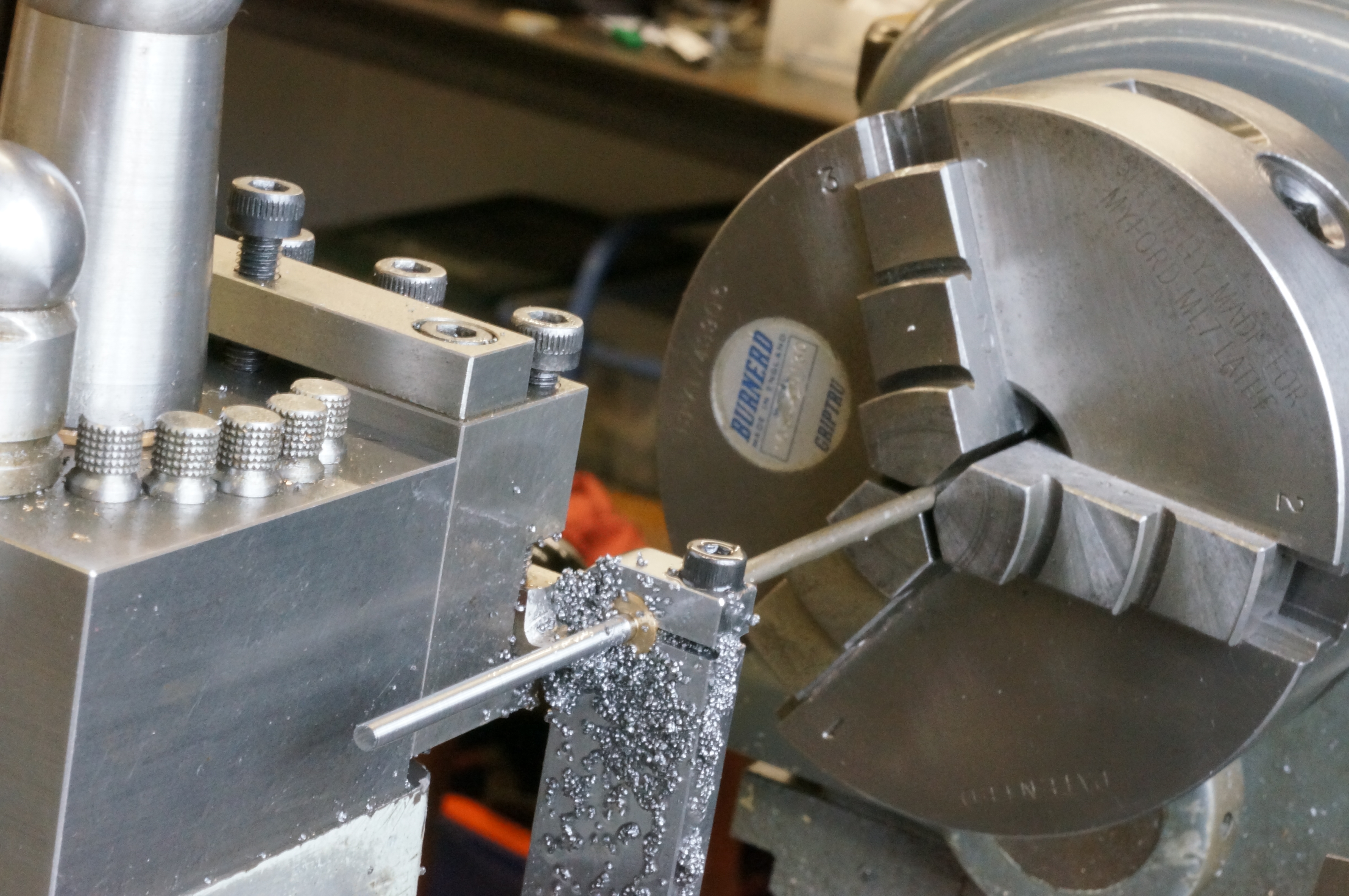
Even with this natty piece of kit, turning the 1⁄8″ rod to size is not quite like shelling peas. I found that at a moderate 1500rpm the maximum projection from the steady without whirling was about 5″. It requires a certain amount of trial and error to get the right final diameter in one pass. Also, because the diameter and roundness of the stock was not perfect, that is reflected in the job. I turned one 5″ length and cut it off to try.
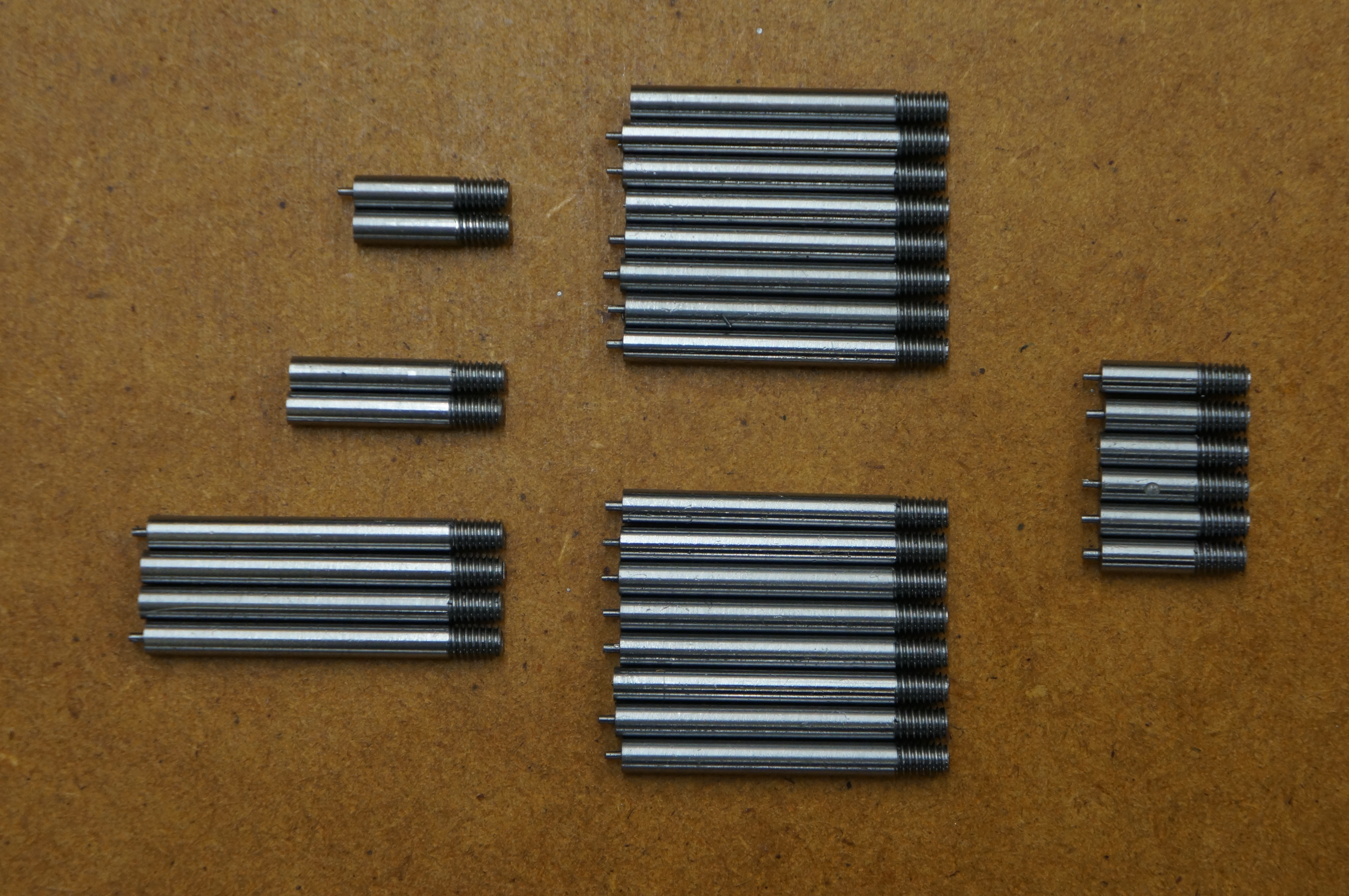
An assembly using studs looks so much better if the studs all project from their nuts by an equal, small amount. I think nothing looks more sloppy than randomly over-long studs. I decided the best way to ensure this was to make the studs slightly over length, threaded only one end, and because the stud and the tapped hole may vary a little, to use each stud for a specific hole, screwed in tight and measured for trimming to final length.
I started with the three studs that hold the timing case to the bearing housing. These do not go into the crankcase, so when screwed home they must not project from the back surface of the plate. With the first one, it took a bit of fiddling about to adjust the 6-BA die to get a good fit in both tapped holes and nuts, and to get a length that looked right, with about one thread projecting from the nut. The outer end of each stud is radiused by hand.
The timing case was originally drilled 2.8mm, which nominally gives no clearance round the studs. While I was not surprised to have to drill out to 2.9mm, I was mildly disappointed that I needed to go to 3.0mm to get an assembly, though this was not really unexpected. Fortunately I had decided to locate the parts with dowels anyway. Making two of the three longer studs, which go through the timing housing into the crankcase or sump, used up the remainder of the prepared stock. All of these studs were long enough to be gripped in the chuck for the second operation.
Next, I put the bush steady back in place and produced another four lengths of 0.011″ rod, each about 45⁄8″ long from the remainder of the 24″ length of stock. The diameter was still a bit variable, but by erring on the thick side, it could quickly be corrected with 800 grit wet-or-dry. (5 hours)
.
2012-11-04 – Washers
I cut up and turned down another length of 1⁄8″ free-cutting mild steel, giving another five lengths. This allowed me to make up the last of the timing case studs. I have now decided that I will use washers under the nuts, and this means that the timing case studs are slightly short. On the other hand the stock washers are a little bit too thick, and the nuts could be reduced a little, if necessary. The die seemed to be cutting small, so I slackened it off a little, but that made the threads too tight for the tapped holes so I had to tighten it back up a bit. I also found that, as machined, the 0.110″ rod is up to a thou or so out of round. This is a risk you take with using a steady; any roundness error in the stock will be reflected in the turned diameter.
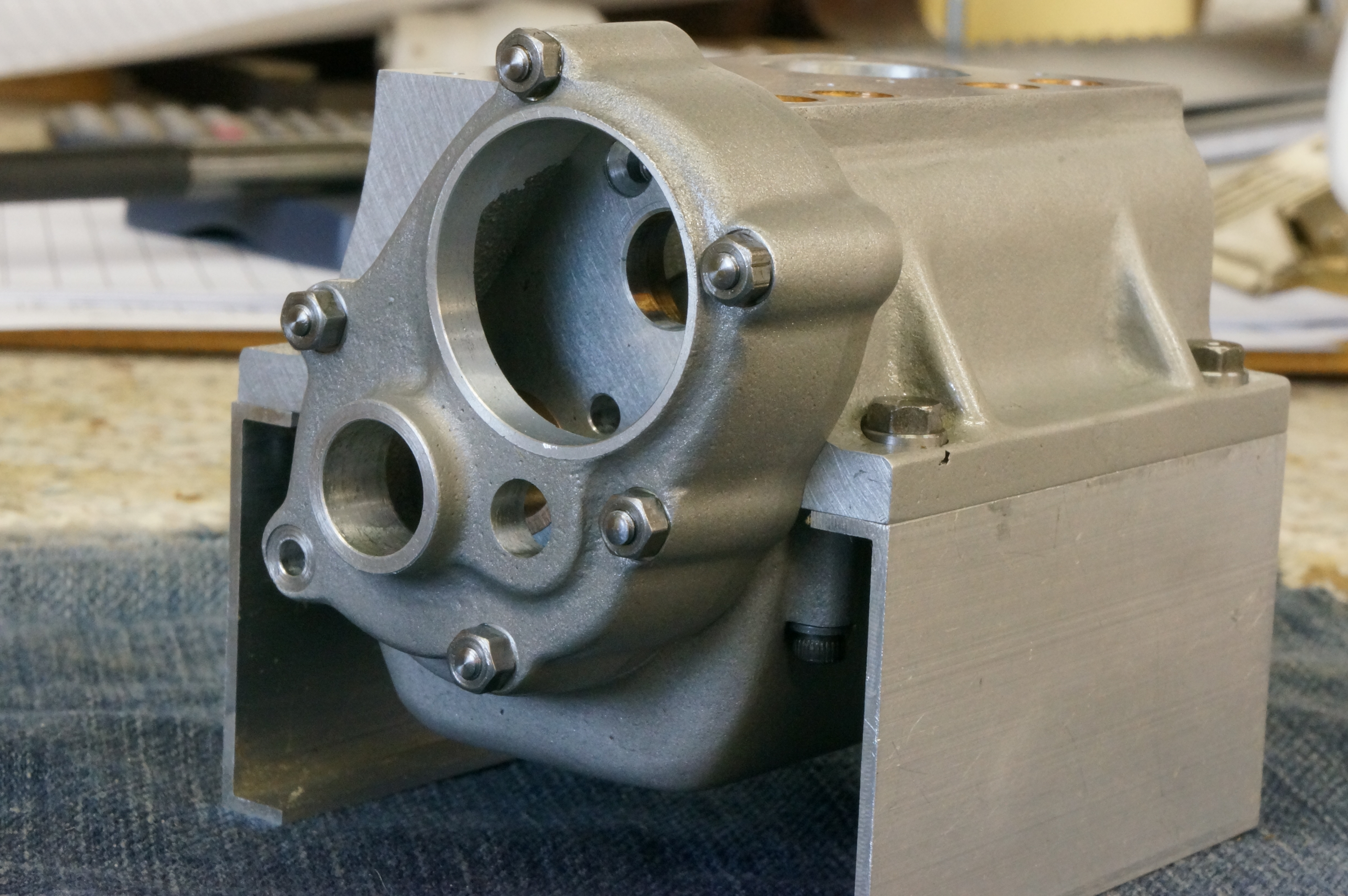
The clearance holes in the sump were always a little suspect on position, but with them opened to 3mm it will go on over 4 studs. The remaining two may need easing a bit more. In a couple of places the standard diameter washers are too big to fit into the back of the spotfaced recess. It is also difficult to get a spanner on to tighten the nuts, perhaps nuts with 7-BA hexagons would help. After opening the three holes on the tappet side to 3.1mm the sump assembled on the crankcase and the timing-end bearing housing and timing case all assembled - a bit tight, but OK. One stud went a bit deeper into the crankcase than the others and is about 1⁄32″ short as a result. (4¾ hours)
2012-11-11 – Flywheel end
I cut and fitted the six short studs for the flywheel-end bearing housing. In this case the holes, which were spotted from the housing onto the crankcase and sump, line-up better; the housing goes over the studs nicely with 2.9 mm holes. These studs still have to be threaded on the outer end. They are too short to grip in a chuck, and I need to read up to see what George Thomas did. Meanwhile, the remaining length of rod was enough for a medium manifold stud. (2 hours)
2012-11-17 – Thinner washers
I decided not to make one of the GHT stud holders. Among other reasons, I have no 60 tpi taps. Instead I simply drilled and tapped a little piece of brass in situ in the chuck to hold the studs. Having another look at the right amount of projection, I concluded that 0.150″ looks right. I finished the six front housing studs to this length and fitted them.
Looking again at the sump studs, the first thing was to experiment with washers. The main problem I had with making a couple of them was deburring after parting off. Perhaps the tool was not sharp enough, but I was left with a tough burr to remove. Certainly, a 1⁄64″ washer looks better that the commercial ones, which are 0.025″ thick. The bought washers are 0.228″ diameter, and fit nicely in a 6mm spotface. If I make my own at 7⁄32″ diameter, they will just fit in the sump pockets. I also tried tapping a couple of 7-BA nuts out to 6-BA to see if undersize hexagons would solve the spanner access problem. They don't help much, and I don't think they look right either.
Finally I made a start on the eight studs for mounting the cylinders. As there is plenty of depth in the top of the crankcase, I made these studs with 3⁄16″ long threads instead of the 5⁄32″ I am using elsewhere. (4 hours)
2012-11-24 – And the rest
Today I cut and threaded one end of all the remaining studs. Even with care over optimising the length combinations, the pieces of turned rod left me two studs short, but the left over stubs of the 1⁄8″ rod were just enough to make this last pair.
Clean up. (3 hours)
.
2015-03-06 – Starting the Coolant Flange Studs
In addition to the 6-BA studs, eight 8-BA studs are needed for the coolant flanges. The tapped holes in the the cylinder head covers are through holes, so the studs are exposed to the coolant, and I am making them from stainless steel.
The first job was turning down some stock (if I remember rightly, I had some 3⁄32″ rod), so the first, first job was to make a new bush for the steady. That done, I made three lengths, each something over 1½″ long. This was enough to cause noticeable wear in the guide bush. I polished the pieces to final size, finding they got very hot on the fingers in the process. An initial check on the stud length indicates they will want 5⁄32″ projection. I made two pieces, threaded for eight threads on end, and parted off at 5⁄32″ length. After a diversion, I made another eight, giving two spares. One I lost over the back of the lathe. After sweeping the floor to reduce the chances of losing more, I spotted it on the window sill behind the lathe. Making another check on the desired projection, I concluded that, with washers, the ideal would be a bit less than 13⁄64″. (2¾ hours)
2015-03-08 – More Washers
Having finally made the decision to use washers on the flanges, how thick should they be? I made a trial one at 1⁄64″ thick. That was a bit too much. I decided on 0.012″, and 0.175″ diameter. I set to and made eighteen of them. For parting off I used a blade thinned to 0.025″ at the business end and sharpened with a slight bevel to ensure parting cleanly with no ring burr.
Next I made a stub mandrel to hold the studs for threading the outer ends. This uses a backing screw to stop the stud being screwed in to the mandrel too deeply by the die. On threading the outer end of the first stud, the die was so tight on the thread it unscrewed it from the mandrel. Trying to hold it with the mandrel and tightening the backing screw merely resulted in bruising the (inner) end of the stud. It needed a pair of locknuts, well tightened, to get the darned thing out of the die. After filing and polishing the radius on the end of the stud, I tried it in place again and eventually decided on 3⁄16″ projection.
On the next stud I tried using a locknut on the front of the mandrel rather than a stop screw in the back, and this works better. Even so, I had to lock the third stud down very tight to get it to extract from the die. No 4 went better, as I began to get the hang of the job. (4½ hours)
2015-03-11 – More Studs
I made the rest of the coolant flange studs today. The RH one for No 1 cylinder had to be shortened 1⁄64″ as the tapped hole was not quite as deep as the others. The first stud went OK, but on the second I used too much force on the mandrel locknut and stretched it. For the third, I tried not using a locknut, with the result that the die screwed it in so tightly that I had to turn the mandrel away to get the stud out. For the next two, I used a backing screw with a locknut and cut the thread in two passes, a method which finally worked acceptably. (3 hours)
2015-03-13 – Cylinder Mounting Studs
Returning to the 6-BA studs, I was missing one cylinder head stud, and two which I had originally made the wrong length for the manifold. More stock was needed. I cut two 4½ lengths of 1⁄8″ mild steel rod and polished them to improve the roundness and reduce wear on the steady guide bush. They ended up at 0.122-0.123″ diameter. I turned, fitted, drilled and reamed a new guide bush for the bush steady, and then turned the rods to size.
After adjusting the die by trial and error for a good fit in the tapped holes, I cut three 1″ lengths, and threaded the bottom end of each. Next, I spent a totally unconscionable time getting the first cylinder mounting stud to the right length, which turned out to be 9⁄32″ projection, giving 9⁄64″ above the flange face. Having settled this dimension, I cut the remaining seven to length, and threaded the outer end, domed, deburred and polished four of them. (4 hours)
2015-03-15 – Cylinder Head Studs
The first job today was to finish the four remaining cylinder mounting studs.
With these done, I moved on to the cylinder head studs. These need to project 53⁄64″. I made one just to check. I screwed each stud in tight. As they had no thread on the top end, I used a No. 0 Jacobs chuck (the tiny 4mm/5⁄32″ capacity one) to grip the stud. I measured each one in place using a rule and magnifier, and set them in a block of wood with eight numbered holes so that each stud could be cut individually to the right length for its particular position. First I cut them all to their required lengths, then threaded them all, domed and polished them, and finally cleaned and fitted them back in place, finger tight.
In measuring the studs for No 2 cylinder, I found one was a little too short, so I made a replacement, and then completed the set as just described.
Turning to the inlet manifold studs, the inner ends of the two lower studs project into the exhaust passage, so I took 3⁄64″ off each. The hole for right hand one (No 2 cylinder) is tapped a little out of square, which I will have to watch when fitting. I will be using undersized nuts on these studs (6-BA thread, 7-BA hexagon and thickness), so the stud projection above the surface will be a little less. I tried it and found 1⁄8″ full to be what was needed.
(The “full” comes from old drawings, and meant “and a bit”, it being down to experience and skill to interpret in context how big a bit was meant. In this case I mean about 5 thou. Making a shade under the nominal dimension was indicated by “bare”.) (5½ hours)
2015-03-19 – Manifold Studs
With the lower studs fitted to the exhaust manifold, the inlet manifold would just go over the two. The next I made were for the carburettor mounting, with ¼″ projection. The four studs for the exhaust manifold end flanges need 7⁄32″ projection. The bottom ones are in through holes, and need to be trimmed on the inside end as well as the outside. Four done and looking good.
To hold the manifolds castings onto the cylinder port faces, there are two shorter studs, projecting ¾ full, at the ends and four longer ones in the middle, 29⁄32″ full. The long ones were not well finished so I gave them a polish before threading. All threaded, domed, polished, cleaned and fitted finger tight. The the exhaust manifold will just push home over the six studs, but the inlet manifold does not want to go over all eight studs. After carefully prising it off with softwood wedges, I found that it was OK without the bottom pair of studs. As these studs have a more generous surrounding sealing area, the holes in the manifold can be opened up. With them drilled out to 2.9 mm the manifold fit with a bit of a push.
The last job today was to make 21 washers for small 6-BA nuts. These are 0.200″ diameter, and 1⁄64″ thick, without a chamfer. (4½ hours)
2015-03-21 – Washers
This afternoon I turned 42 standard 6-BA washers (0.220″ diameter), and did a trial assembly of the castings to see how all the studs and washers looked. (2 hours)
.
Keys
2013-01-21 – Making stock
I hacksawed out a piece of 1⁄16″ gauge plate, milled it to ¼″ wide, and filed the long edges round to form a section the keys could be cut from. (1 hour)
2013-01-26 – Key cutting
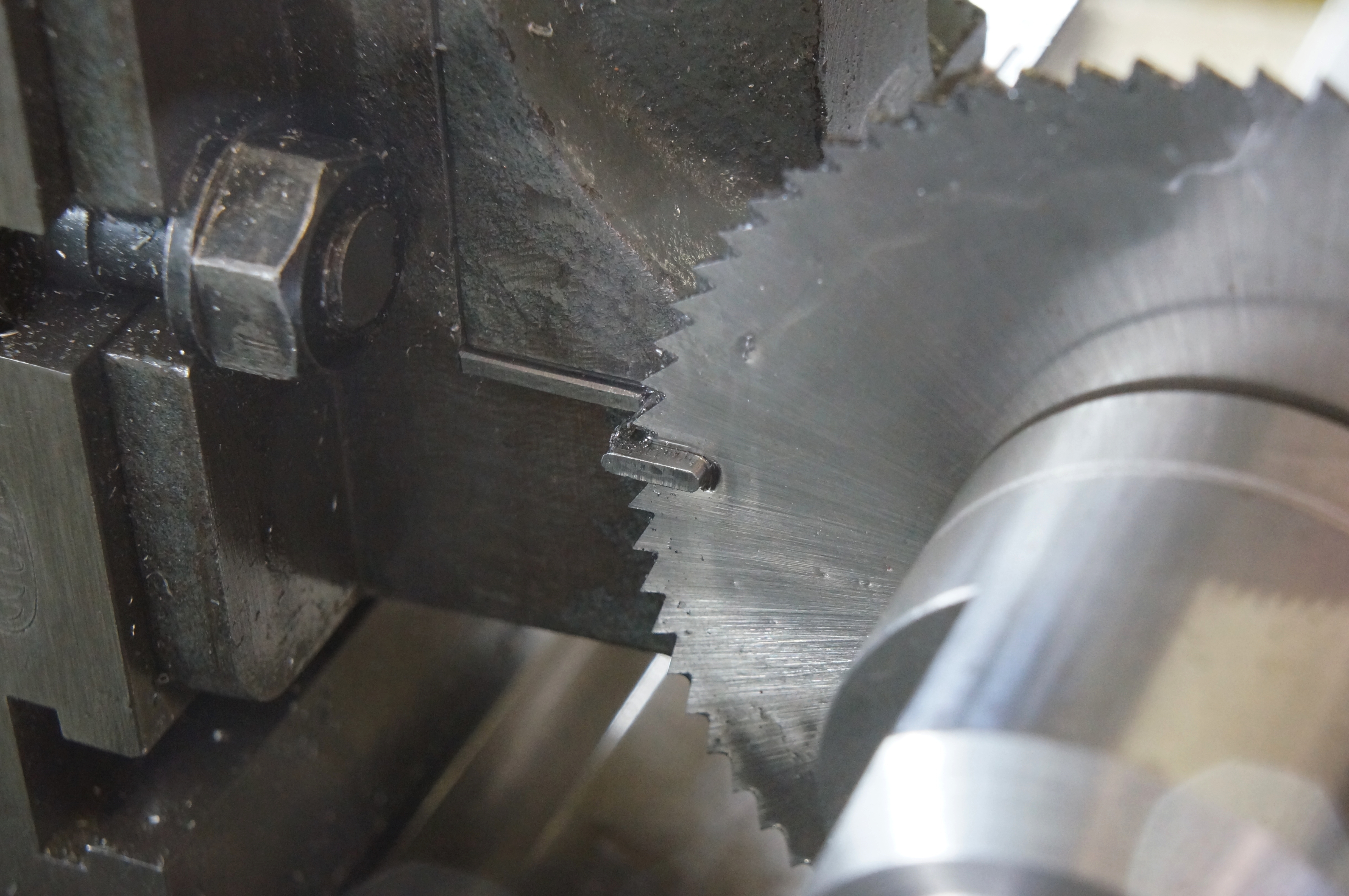
I used a fine-toothed slitting saw to cut keys from the prepared section. I made four while I was at it. (¾ hour)
.