
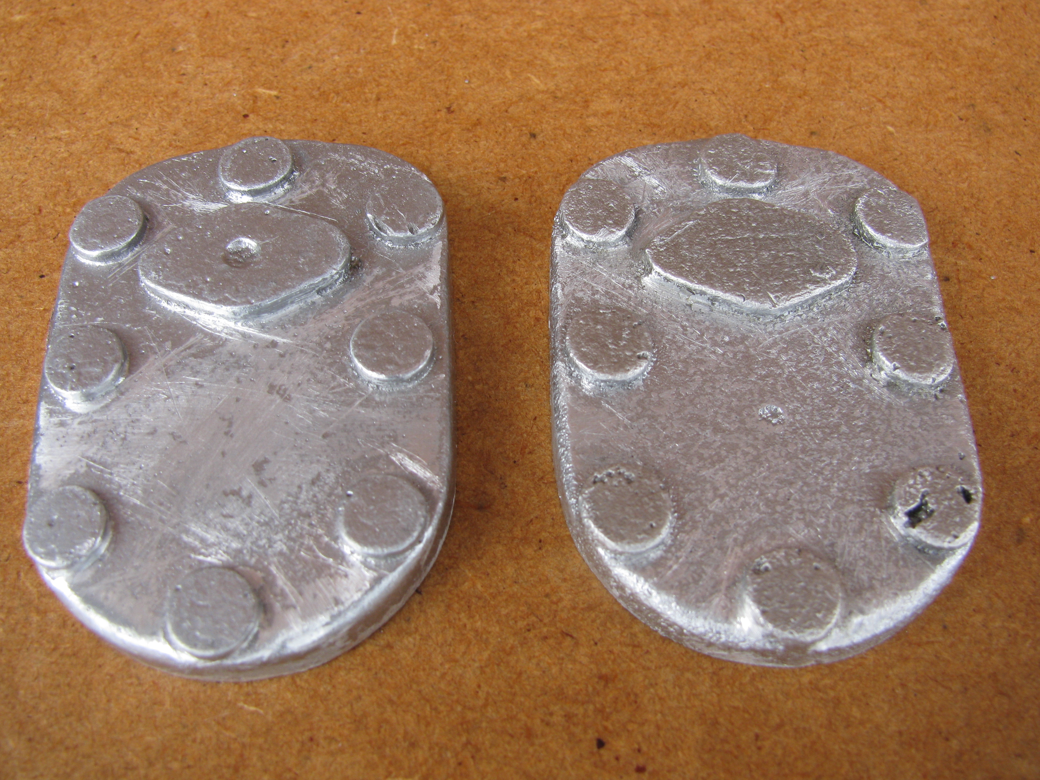
Cylinder Covers

These two castings are quite different in surface finish, one is quite rough, with a number of very small holes, and lumps round some of the bosses, while the other looks almost diecast. The water connection flange on this casting is bigger than the one on the cylinder barrel. The bolt hole positions indicated by the bosses are not exactly to drawing, but will allow a perfectly reasonable layout which has been drawn. These bolt positions appear to match the cylinder heads well.
2010-07-24 - Roughing and titivating

As these are prominent, and as supplied the two castings are quite different in appearance, presumably having come from different batches, I decided to do some cosmetic work on them. I cleaned up some of the knobbles and crisped up the moulding of the bosses using needle files and rifflers. After taking a roughing cut on the undersides (one is quite close to finished thickness at one end) I took them to pinch a few seconds in a sand blast, which has done an excellent job of making them look a pair and is quite mild in effect. A bit more hand work may be warranted, as the bosses for the water pipe flanges are much larger than the flanges themselves, which may look a bit odd if they are left. On the other hand, it will be difficult to disguise any such work, even with further sand blasting. I don't seem to have a photo of the covers after sand blasting. There is a small blow hole in one of the bolting bosses. This won't be seen when covered with a washer so I filled it with a spot of JB Weld epoxy. (2½ hours)
.
2013-05-04 - Facing
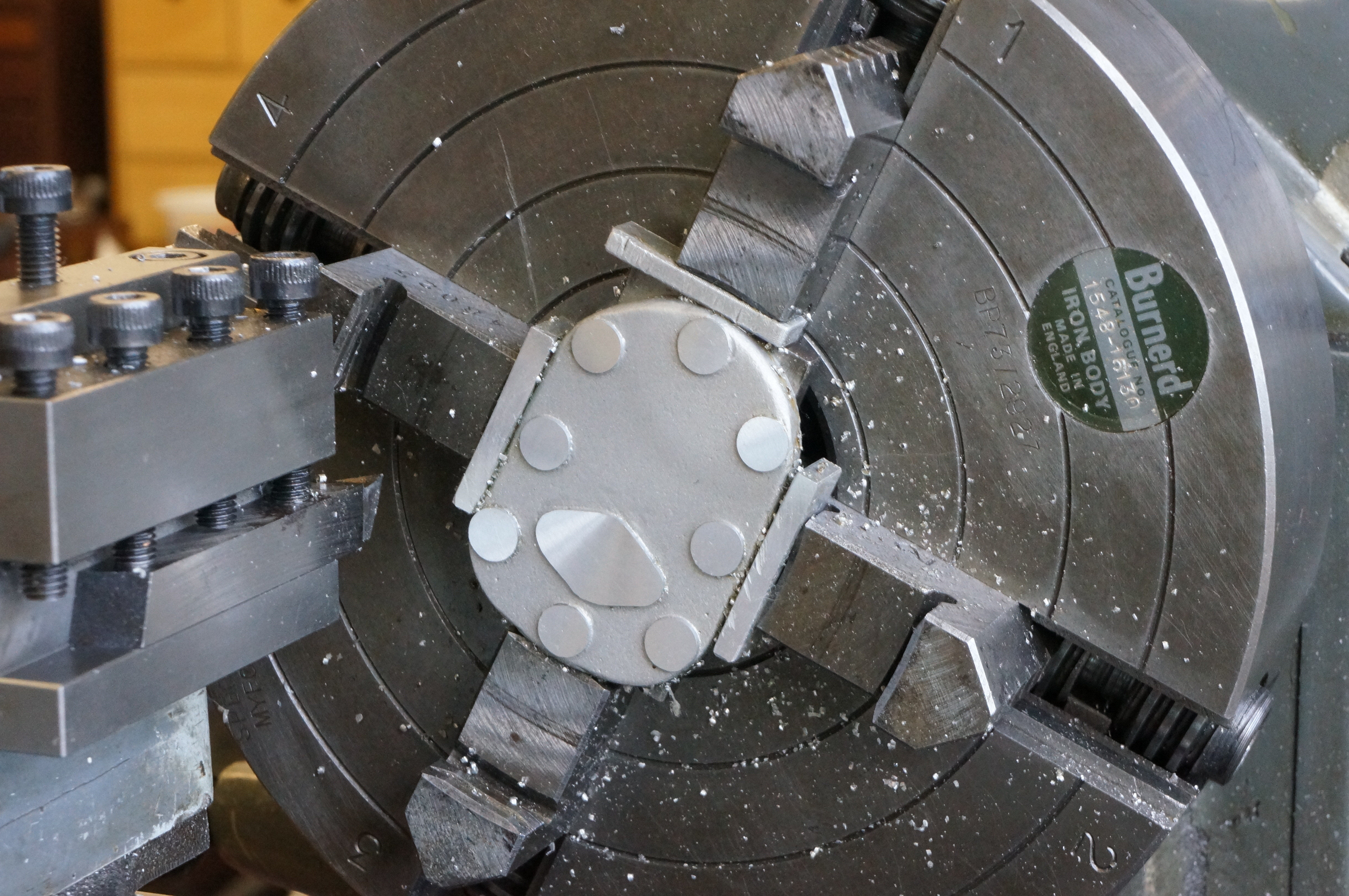
Facing the outside of the rougher one, the first cut gave a terrible finish. With another 8 thou to go, I cut the speed from 300 to 200 rpm, and tried a different tool with less top-rake. The next cut of 4 thou was vastly better. The better looking casting machined much more easily. Taking the sealing faces to finished size, I got a couple of grooves in the gummy one, but they should lap out. The better one evidently was not bedded perfectly in the chuck as there is a variation in finished thickness from +0.0025″ to -0.0015″ thou. (2 hours)
2013-05-09 - Profile milling sides
Today I started by milling the side edges of the covers taking a little at a time, primarily so as to get the best fit to the profile template, but also trying to take the bolting bosses into consideration. Later I started doing the same with the cylinder heads.(1¾ hours)
2013-05-18 - Profile milling back

While working on the cylinder heads, I used the same setup to cut the back edges, just up to the limit of the bolting bosses.
2013-08-24 - Water flange holes
While there was a suitable set-up in the lathe, I drilled and tapped the water flange holes in the covers. (1½ hours)
2013-09-12 - Water flange template plate
Having spent some time thinking about how best to profile the water flanges on the head covers and cylinders, I cut a piece of 3⁄32″ gauge plate. It occurred to me that in full size a good designer might well make the flange on the casting a little larger than the pipe flange to allow for any slight discrepancies in the casting. This seemed a good idea, so after measuring the cylinder castings to see if was feasible, and some wavering, I decided to go for it, and milled the plate to a rectangle that would leave an extra 0.010″ all round, and drilled close-fitting bolt holes and a central hole to be used for alignment and to take filing buttons. (2½ hours)
2013-09-13 - Water flange template profile
I milled a sloping edge on another piece of gauge plate to the correct angle for the template flanks (a template template) and used it to mill the flanks to a calculated measured length. I turned filing buttons the diameter of the middle portion and used them soft to file the radii on the template and blend the flanks in. Next I turned small buttons for the ends radii in silver steel and hardened them. Filing and finishing the template took rather longer that I would have liked as it took nearly an hour to find the button I dropped. Had I known it would take that long to discover it on the bench shelf and not on the now spotless floor after all, I would have made another one instead. With the profile eventually finished, I hardened the template and had a tidy up. (4½ hours)
2013-09-15 - Water flange profile
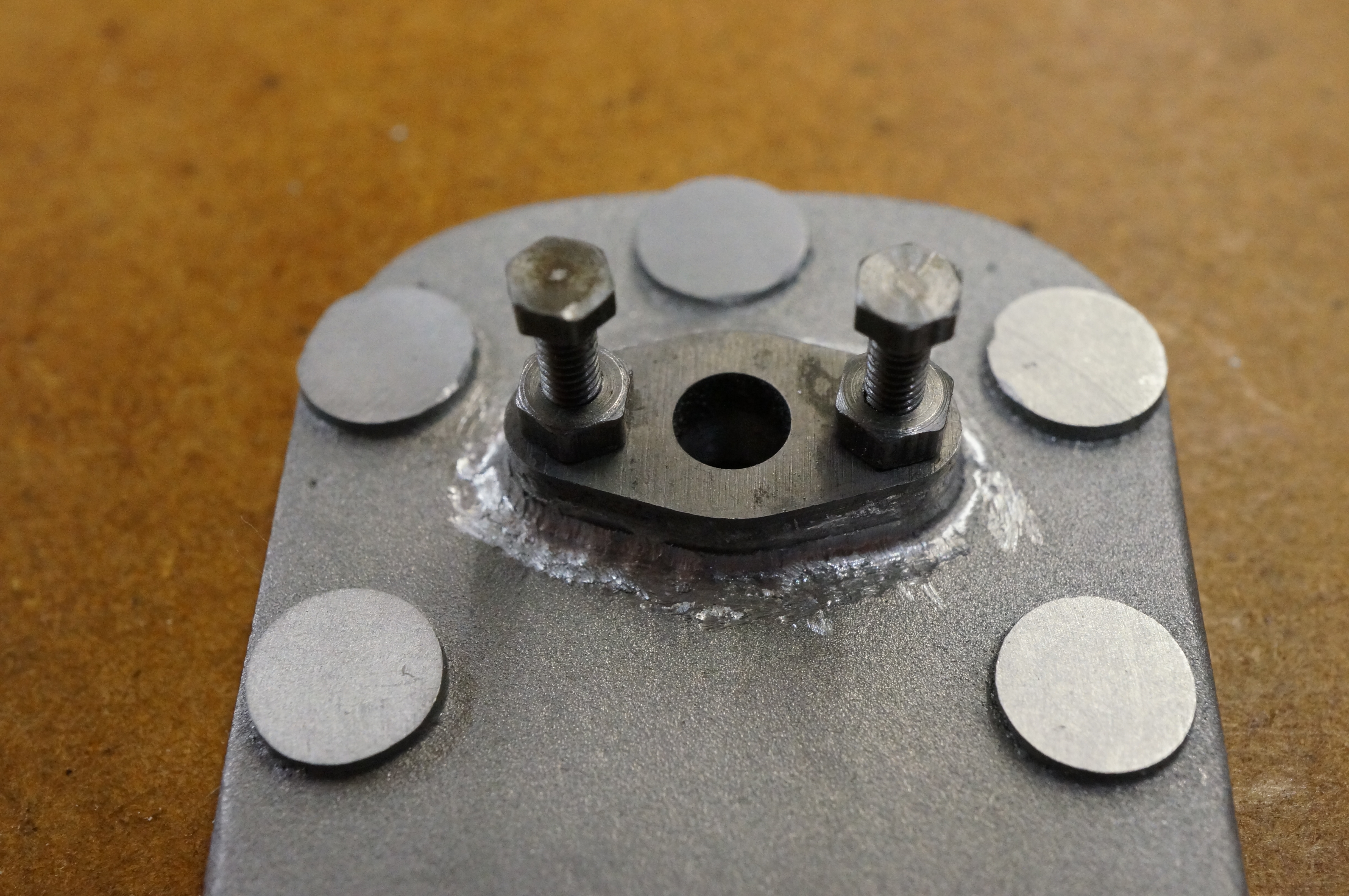
While toolmaking, I made a shell end-mill to machine the bolting bosses concentric with the holes. (It never gets used.) Using the profile template, I made a start on sculpting one of the flanges. The photo shows what it looked like after the first stage, using a burr in the Dremel. Later, I carried on with a round riffler and a wad of 240-grit wet-or-dry paper held with little pair of bent long-nose pliers. (2¾ hours)
2014-03-28 - Drilling

With the cylinders drilled earlier today, I next drilled both the covers, again using the drilling jig and remembering the 0.010″ shim to pack the cover away from the end plate to allow for the surface being set back from the cylinder port face. After tapping the holes in No 1 cylinder I was pleased to find the cover fitted over the studs quite easily, despite the holes being nominal size. Clearly the jig is doing a good job. (1 hour)
2014-04-07 - Profile milling


With the rotary table already set up on the mill for doing the same job on the Cylinder Heads it was a quick job to get the covers done at the same time. (2 hours)
2014-04-21 - Fettling bosses
After making the decision as to which was which, I started on No 2, working mainly with a round riffler to bring the bolt hole bosses to match a 0.230″ diameter filing button. The bosses for the particularly awkward holes, either side of the valves, are not going to clean up fully. (2¼ hours)
2014-04-22 - Fettling a radius
I finished all the bosses on No 2 cover, and settled on a 5⁄64″ radius round the periphery and worked slightly over half way round before deciding that was enough close work for one day. (3 hours)
2014-04-26 - More fettling
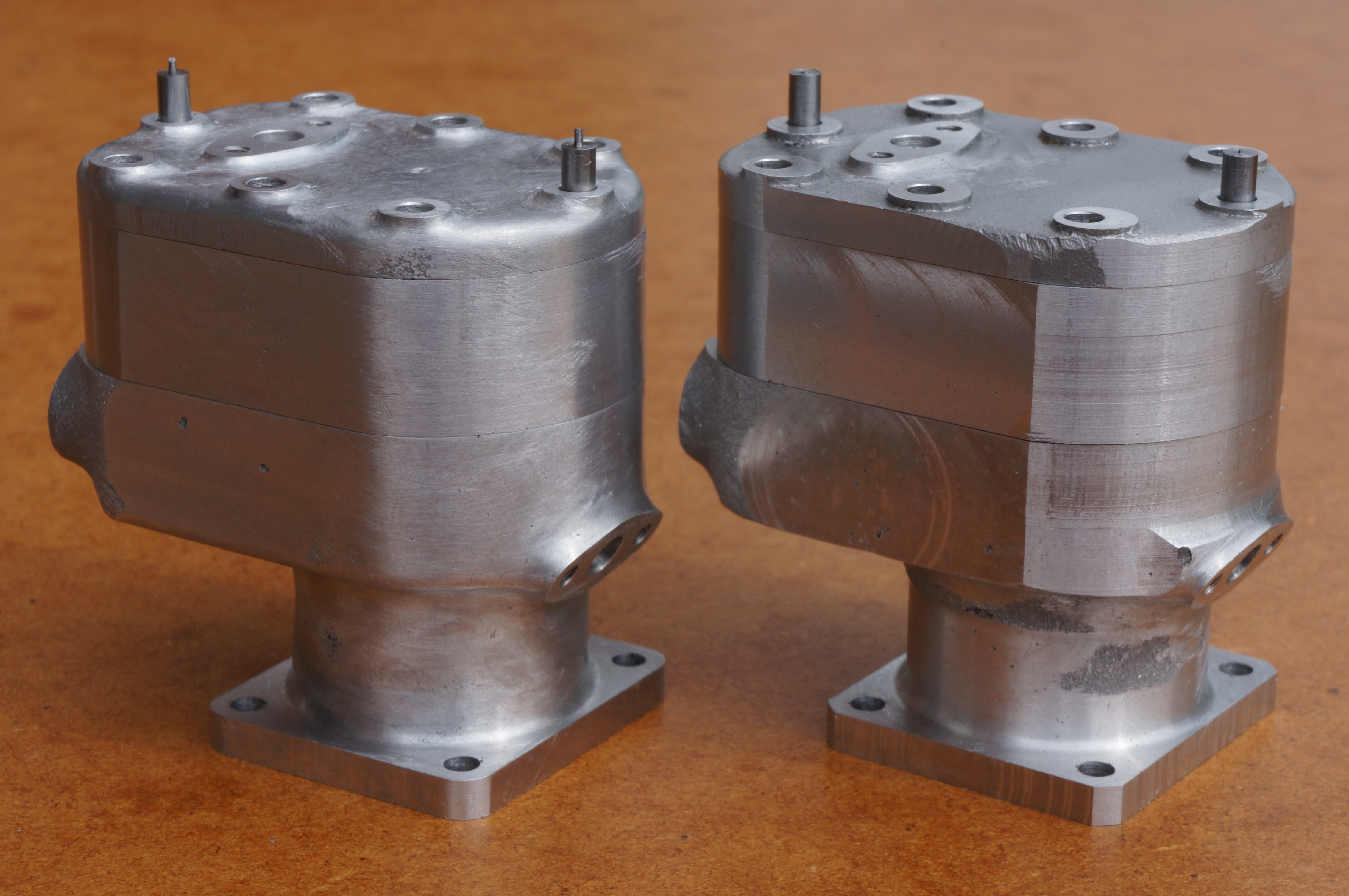
After completing some special sump nuts this morning, I finished working the edge radius all round, then finished smoothing the top surface by rubbing all over with 400 grit wet-or-dry paper wrapped round the end of a match stick. This one is now largely completed. The photo shows one cylinder assembly with the hand finishing nearly complete, and the other largely untouched. (3 hours)
2014-05-20 - No 1 Cover
I made a start on No 1 cover today, working round four of the stud bosses, none of which has cleaned up to a full, round face. (3 hours)
2014-05-24 - More fettling
Today I finished work on the bosses and the edge radius on No 1 cover, and started removing scratches. (2½ hours)
2014-09-13 - More fettling
Briefly back to this at the end of today's session mainly working on the cylinders. More rubbing out scratches. (1¼ hours)
2014-09-22 - More fettling
I used paper wrapped over the tip of a little wedge of wood to give a broader rubbing edge than a wrapped matchstick. This one is now also ready for sandblasting. (1¼ hours)
2015-03-08 - Lapping
.