
Carburettor Body
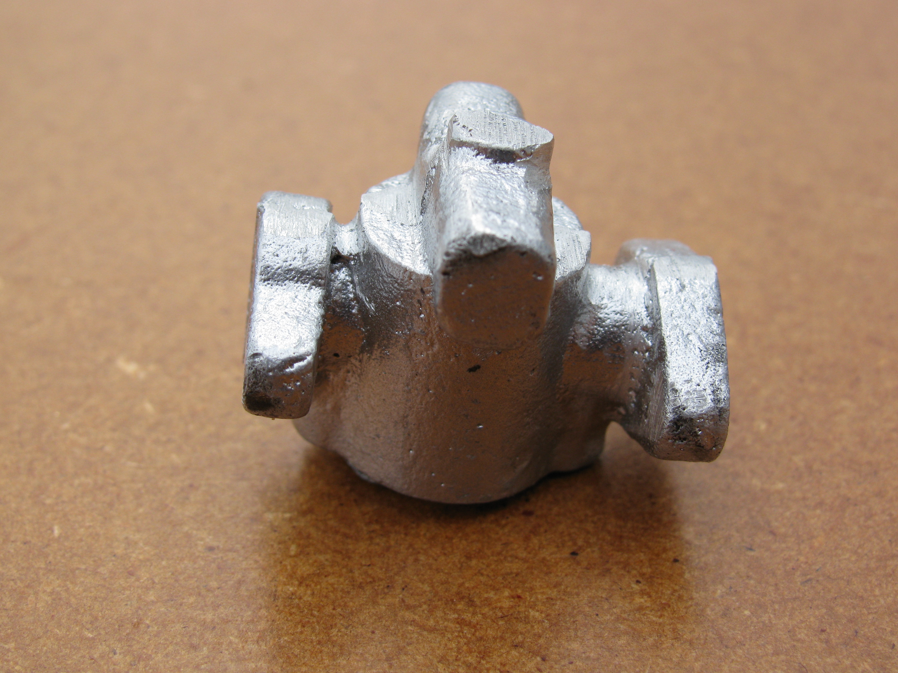
A rather twee casting is provided. I forgot to photograph it before starting to remove the large amounts of casting flash it carried. The main body is larger in diameter and considerably longer than drawing, allowing some scope for modifications if required. As drawn, the mounting flange does not match the inlet manifold. This error has been reproduced on the castings. The inlet and barrel flanges are also larger than drawing.
.
Design
For his Seagull, Graham Meek has done some very interesting, and well written up, work on the carburettor design.
I discovered these articles after I had done some of the early work on the body casting, and I am in two minds about it. On the one hand I could continue with the rather underwhelming casting and produce the carb to the original design, knowing and accepting its shortcomings as a challenge, and seeing for myself how difficult it proved to get it working. On the other hand, I have little time invested it it to date, and it might be better to start from scratch with a new design incorporating many of Graham's improvements, and with a new, fabricated body.
From a cosmetic point of view, the alloy casting would take a lot of hand work to get it looking as good as the rest of the castings. In any case, a full-size engine of the era that this design represents might well have had a gunmetal carburettor. Graham Meek's alloy cube would not be in keeping with the period look I want. The revised design would involve four additional screws. It may be difficult to avoid the appearance of a porcupine.
I am not very keen on making the barrel and its spindle as a single piece of brass. With this casting there should be enough room to have a separate steel spindle, but designing a suitable connection in the space available is tricky.
.
2013-02-02 - Roughing out
This is the only casting I have done no work on yet. It will not actually be needed until much later in the build, but I like to get the castings roughed out at an early stage so that I can assess them and have time to think through any problems.
In doing some preliminary filing to allow a good set-up in the 4-jaw chuck, I found the casting to be very soft, the file was picking-up after just two strokes. The housing for the jet tube, across the back of the barrel, (uppermost in the photo of the casting above) has been cast with a discrepancy between the two halves of the mould which is going to make things awkward. I filed the ends much closer to finished size to get a better idea of what metal was available where. It looks just about doable.

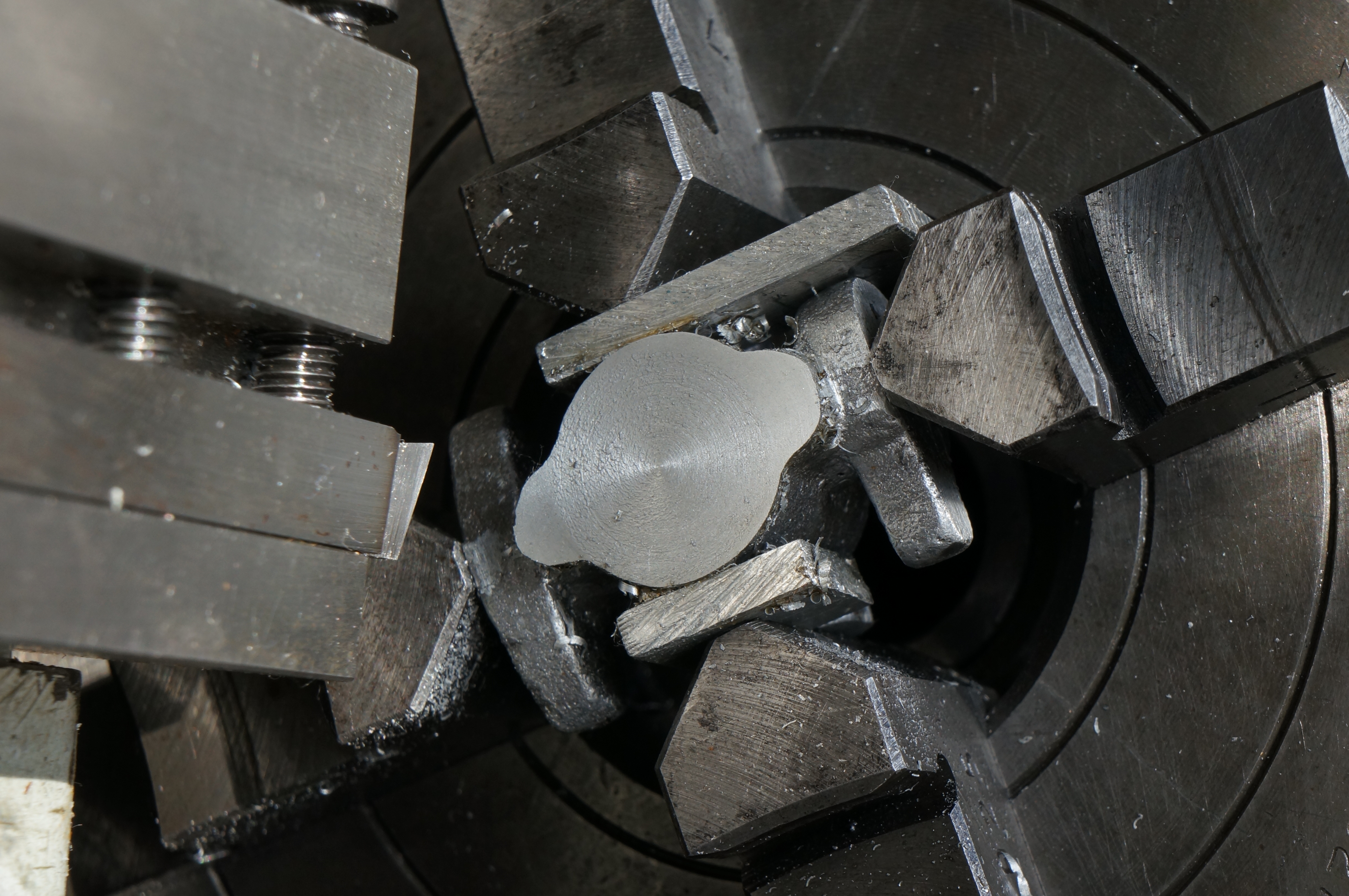
Starting with the front barrel flange face to get a good big datum face, this produced a poor surface finish. I tried a sharp pointed tool without a radius. That was considerably worse. Buy using a tool with a radius, a fine cut, and a slow speed (from 1020 rpm down to 425) I eventually produced a perfectly reasonable finish.
The second operation was on the bolting flange, aiming to get the jet tube housing level. I achieved that, although the two machined faces are not dead-on square yet. The neck below this flange is oversize, which means that, unless the flange can be made longer than the design, it will be difficult to find room for the fixing nuts. Making the flange bigger on the carb body seems possible, but the Inlet Manifold does not look promising, so I decided to rough that out too for a look-see. There is not much scope.
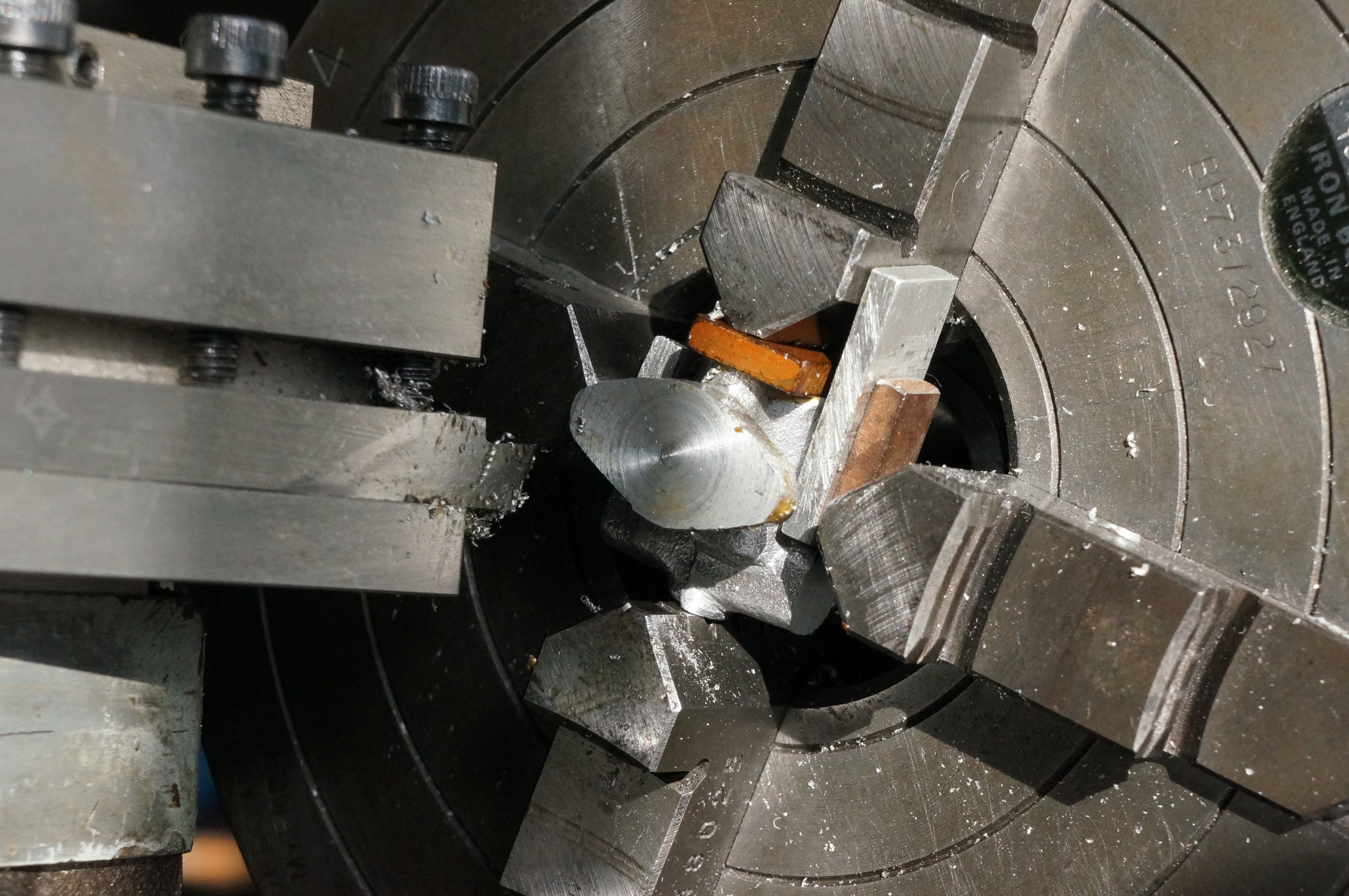
Set-up three was to machine a previously filed end face of the jet tube housing to provide a datum in the third plane, square to the front and bolting faces.
Carefully examining the result, it was clear that one side of the casting is somewhere between 0.03″ and 0.05″ higher than the other, and by trying to compensate for this in facing the bolting flange I have got the vertical centreline badly skewed. The bolting and inlet flanges now look to be a problem as well as the jet tube housing. The inside faces of these flanges are also compromised by the offset in the mould. There is probably enough metal to get round it but it will not be easy.

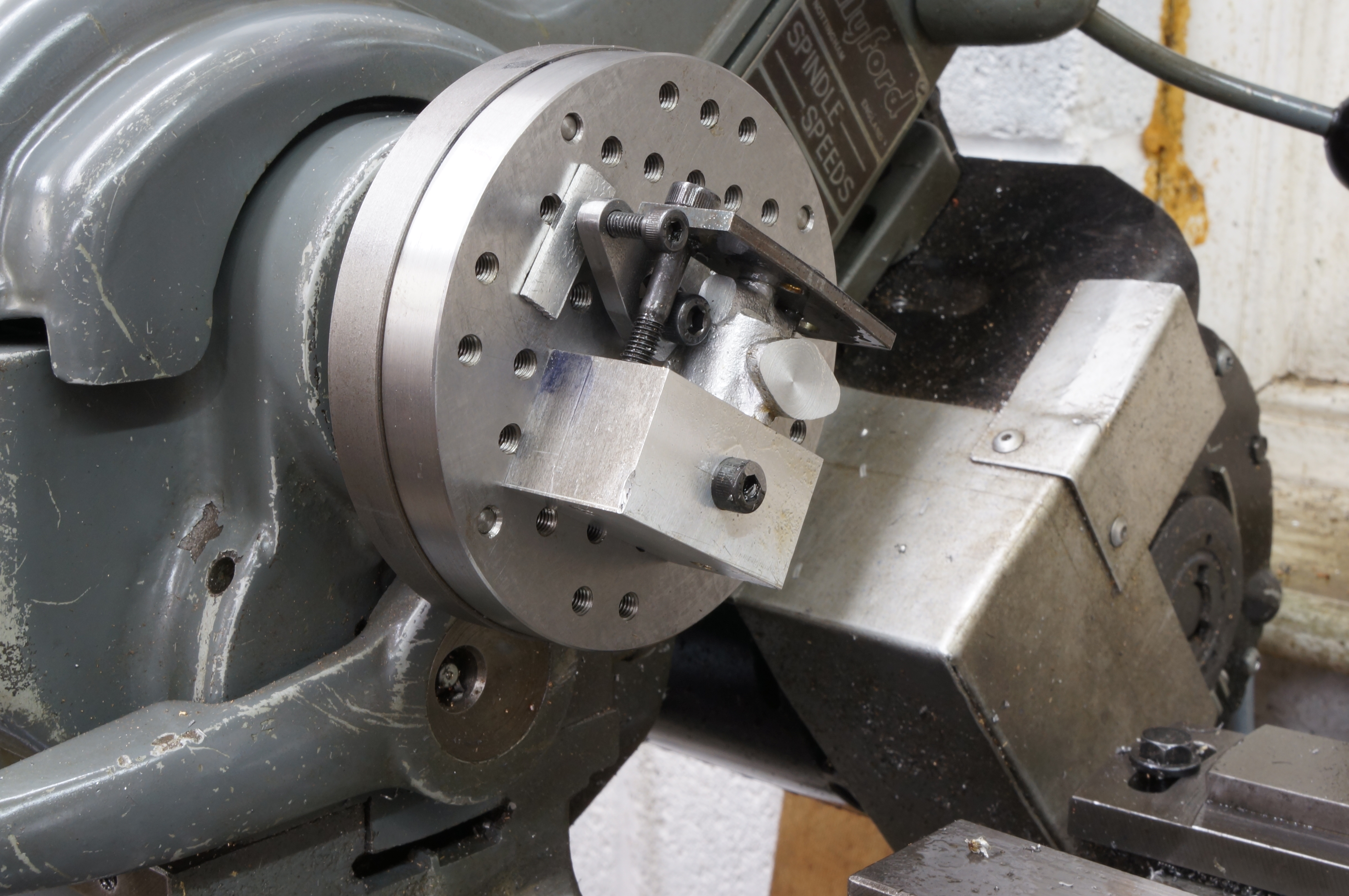
I wanted to get the inlet flange square to the vertical centreline of the casting to provide a better datum than the bolting flange is at present, even though this would conflict with the jet tube housing. I decide to use a couple of rollers against the choke tube to get it square to the flange. Unfortunately the result still looks very lopsided. The top and bottom flanges are not parallel, and because I initially took more off the top flange than proves to have been prudent, the overall height allows no more scope for mucking about, it is on size (just about) on the shorter side. Getting the exact design height is not particularly important, it can be adjusted to suit the casting but the flange thickness is also a worry. Hmm. This may be a scrapper. I may try giving the bolting flange a wallop to see if I can get it more square with the rest of the casting. If I break it I can start again. (4 hours)
2014-10-01 - Adjusting the flange
While working on the manifolds today, I decided to give the carb. bolting flange a little squeeze in the vice. It looks better, but may need a bit more.
2014-11-29 - Re-machining the bolting flange
I made a squared block so that the body could be set up to have another go at the bolting flange face. It was just possible to clamp the casting to the holey faceplate by the little lug on the inlet flange, and at the same time get bolts past to clamp the front face of the casting to the angle block.
I tried two different tools to take the small amount necessary off the flange face to true it up. Both tools gave a nasty finish, and I took off more than I really wanted trying to get it better, but it looks as though the overall length and flange thickness will still be just about doable.
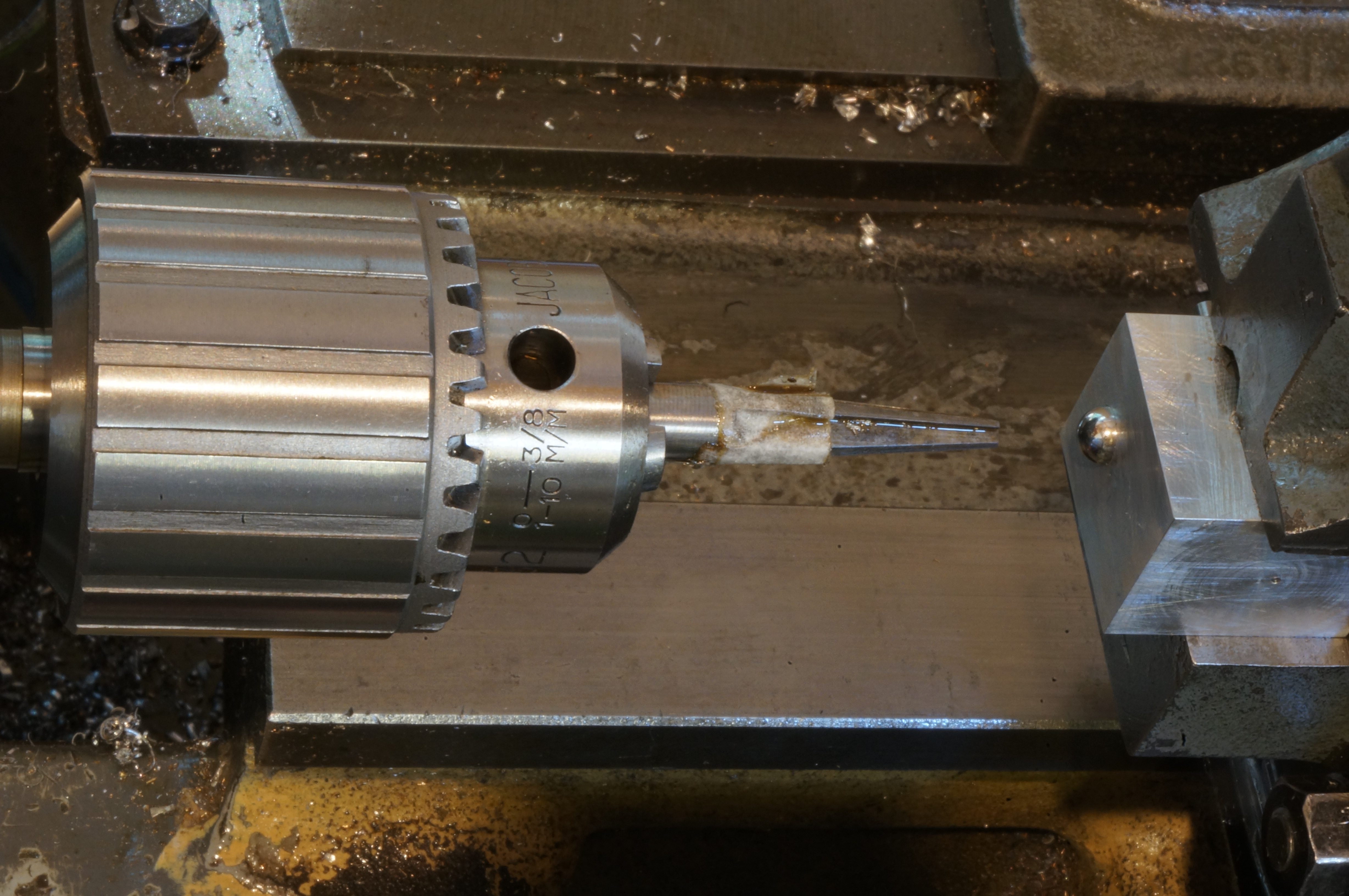
2018-06-09 - Starting a taper reamer
I turned a 10° included taper on a piece of silver steel, as a start to making the venturi.
I then turned back to to the carb body, trying to fathom out how to get datums to ensure the cast surfaces end up concentric with the holes through them. I took a milling cut over the back of the barrel chamber and the jet tube housing to ensure there is enough metal to clean the casting up to size. Actually it came out a couple of thou under. That is OK, and now defines the horizontal centreline plane of the barrel and jet tube. The cast draft tube defines the position from front to back of the carb. (3 hours)
A rethink
By this time, and after a long time with little done on the engine because of a house move, I had decided to make a carburettor with many of the additional features described by Graham Meek, as mentioned at the top of the page. It will have a fixed full-throttle stop, an idle stop, an adjusting screw on the jet air hole, and an adjustable air bleed for idle mixture. Unlike Graham's it will remain a up-draught job and will eventually resemble the original Westbury design, but it does mean I will need to abandon the original kit casting. Fortunately. There is, however, a lot of work in making a new fabricated or cast body that looks right, so as this one is rather experimental, I will start out with a trial body in the form of an ugly rectangular lump cut out of the solid.
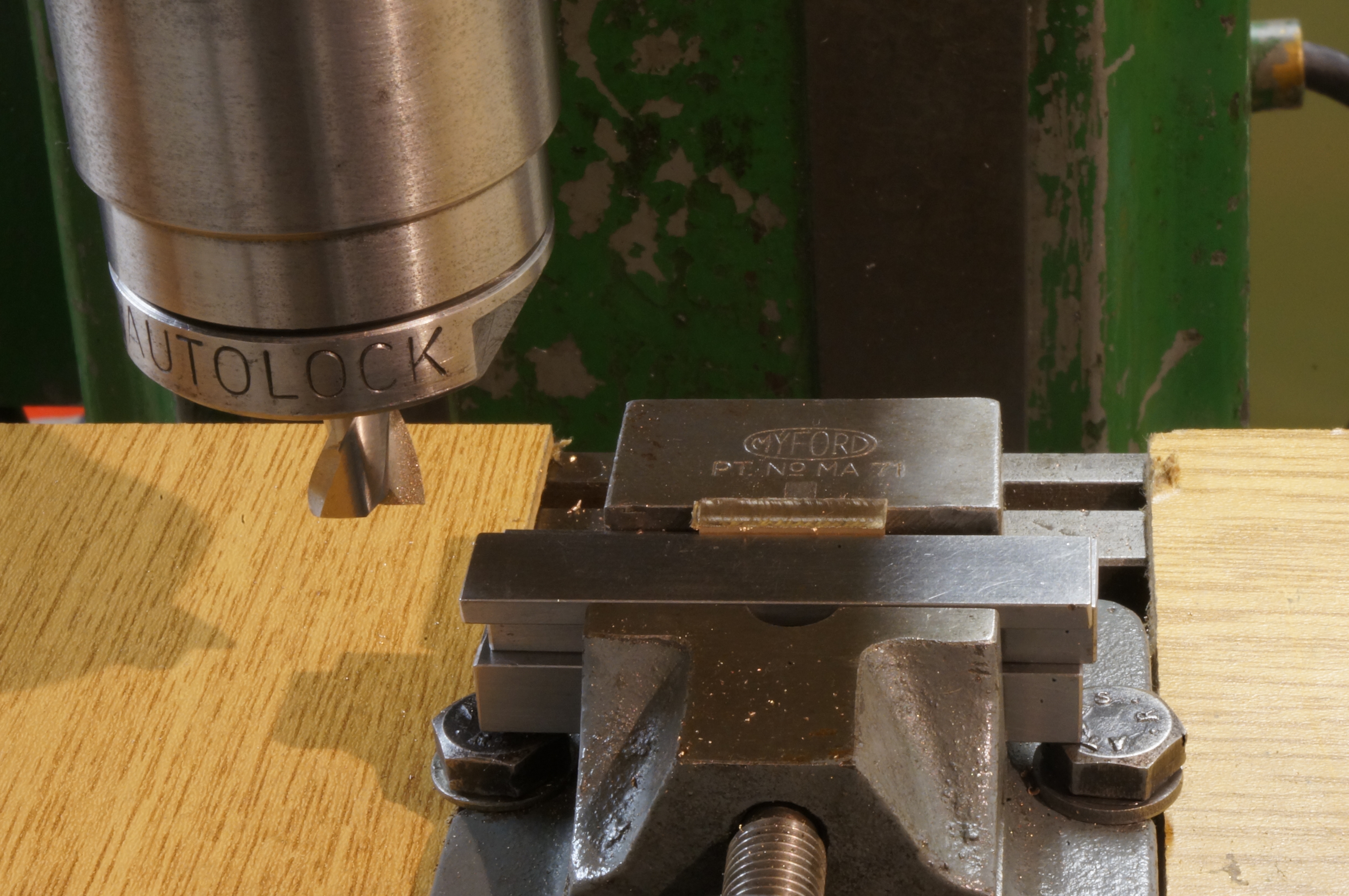
2019-03-25 - Making a milling jig
Today I made a square block for a jig to hold the reamer for milling the flutes. A tool for a tool. As the milling machine is currently stripped down, this job is being done in the lathe. After machining the sides I rubbed them down on a fine diamond stone to improve the parallelism and dimensional equality. (2½ hours)
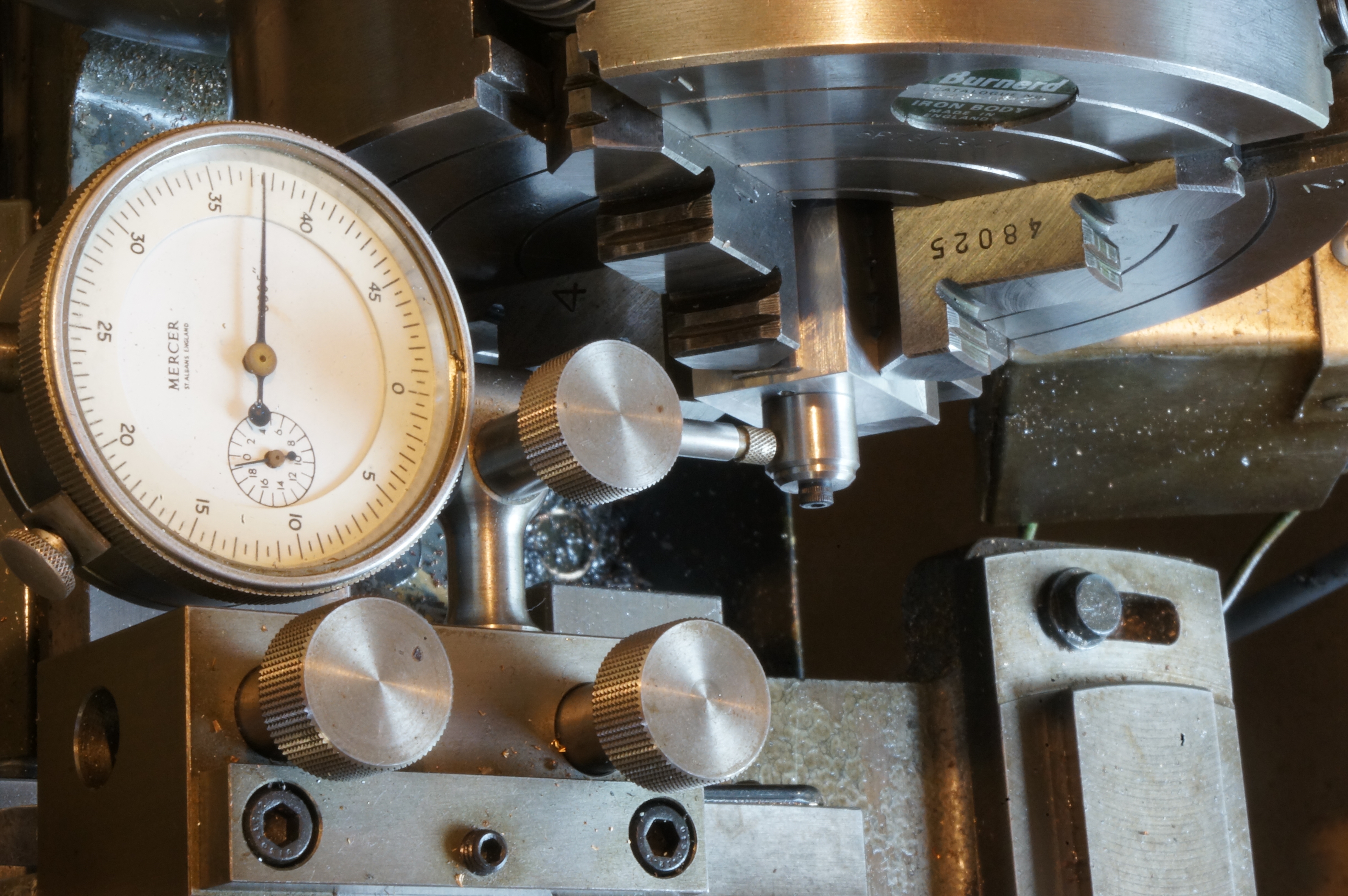
2019-03-30 - Setting the angles
With the block set up to run true to ½ thou, I faced, centred, drilled and reamed it for the 5⁄16″ reamer shank. I then drilled and tapped M4 for a locking screw. The reamer is designed with a cross-section than is constant in shape; and this means the flutes need to be milled at a compound angle. The table of the swivelling vertical slide was rotated to 2.8° for the cutting edge depth, and then more laboriously set, the wrong way at first, to 0.9° in plan, for the flute depth. This was done using a dial indicator to measure the tangent. (2½ hours)
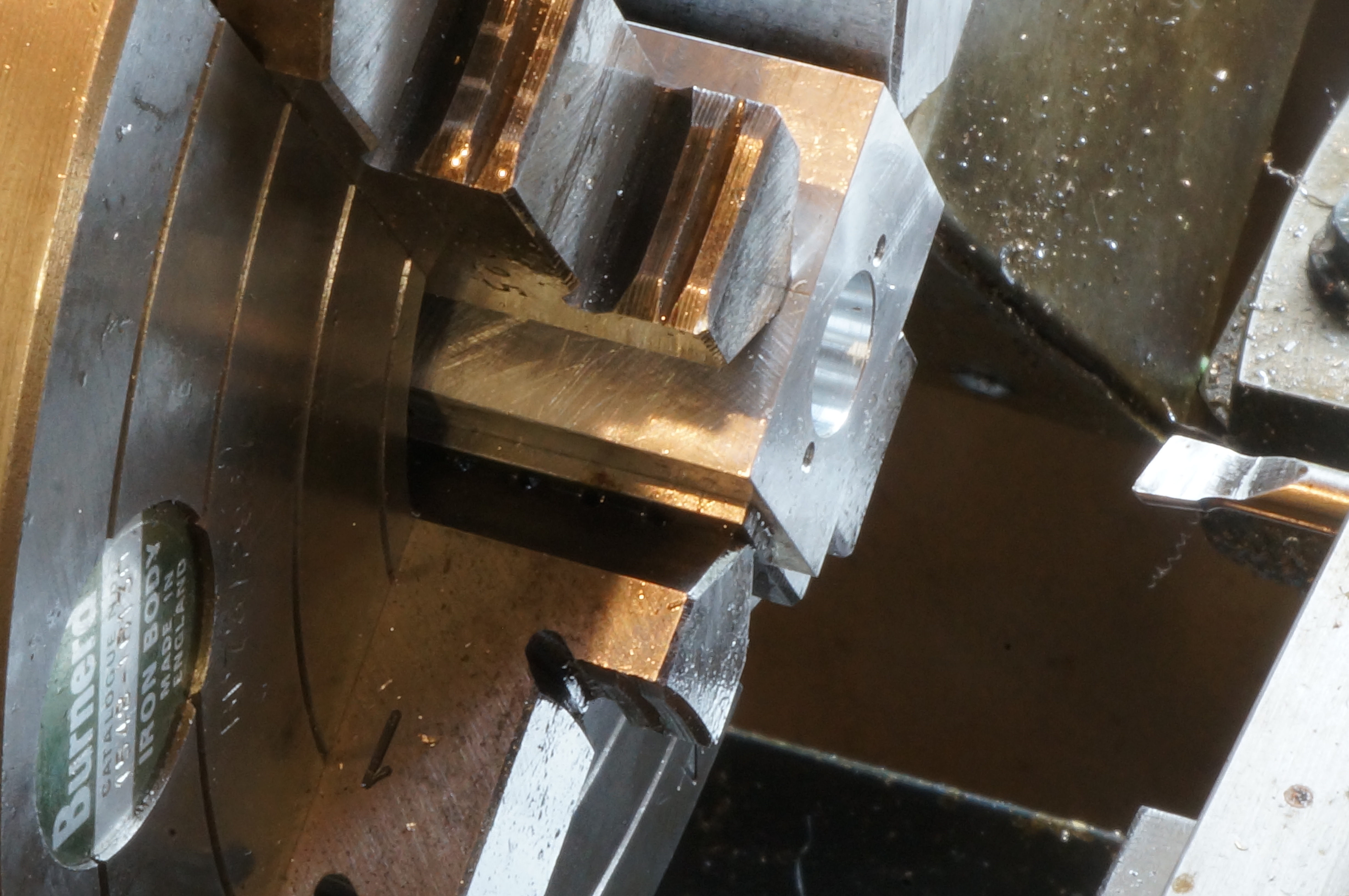
2019-03-31 - Milling the flutes
Today I machined the reamer flutes, cleaned it up, and file the relief angles behind the cutting edges. Later, I cut a 1′ length of 1½ square aluminium alloy for the new body. (2 hours)
2019-04-20 - Making a radius tool
The carb. inlet needs a 1⁄8″ radius flare. Having ground a 1⁄8″ radius on a very hard ¼″ square tool bit, I used that to put a convex radius on a piece of 3⁄8″ diameter silver steel, taking the finish cut in bottom back-gear. I also faced the sides of the carb. body block. (2¾ hours)
2019-04-21 - Squaring up the Body
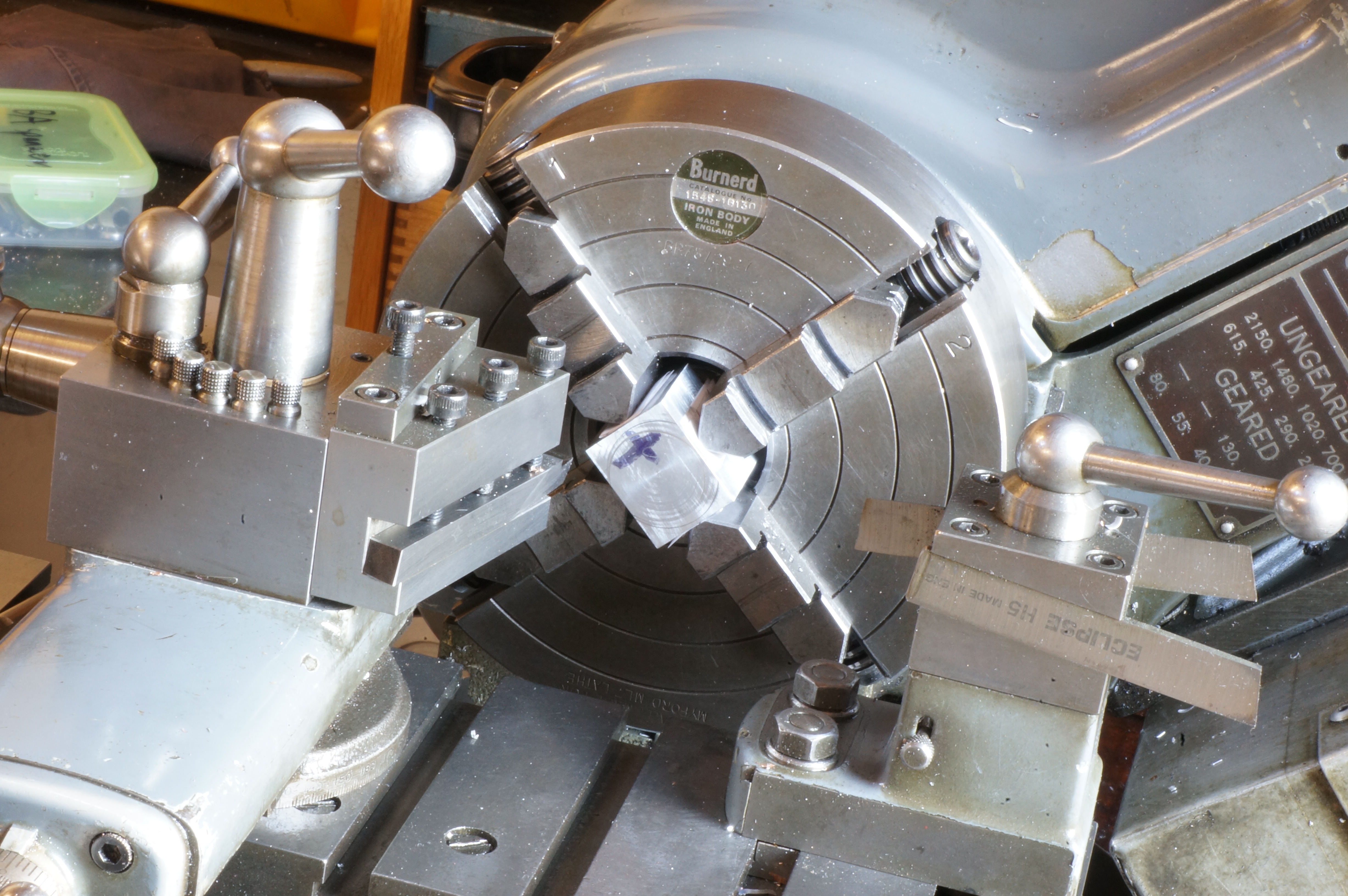
First this afternoon I cut a little piece of tough gunmetal for the front flange.
The body has holes in all directions that need to be lined up accurately, so it is important to make the block accurately square. I roughed out the remaining sides of the body block, turning the faces using the 4-jaw chuck. The squareness checked out pretty well, so I finished all the faces to size. Well, it ended up 0.020″ short, top to bottom, but it won't matter. Tidy up. (2¾ hours)
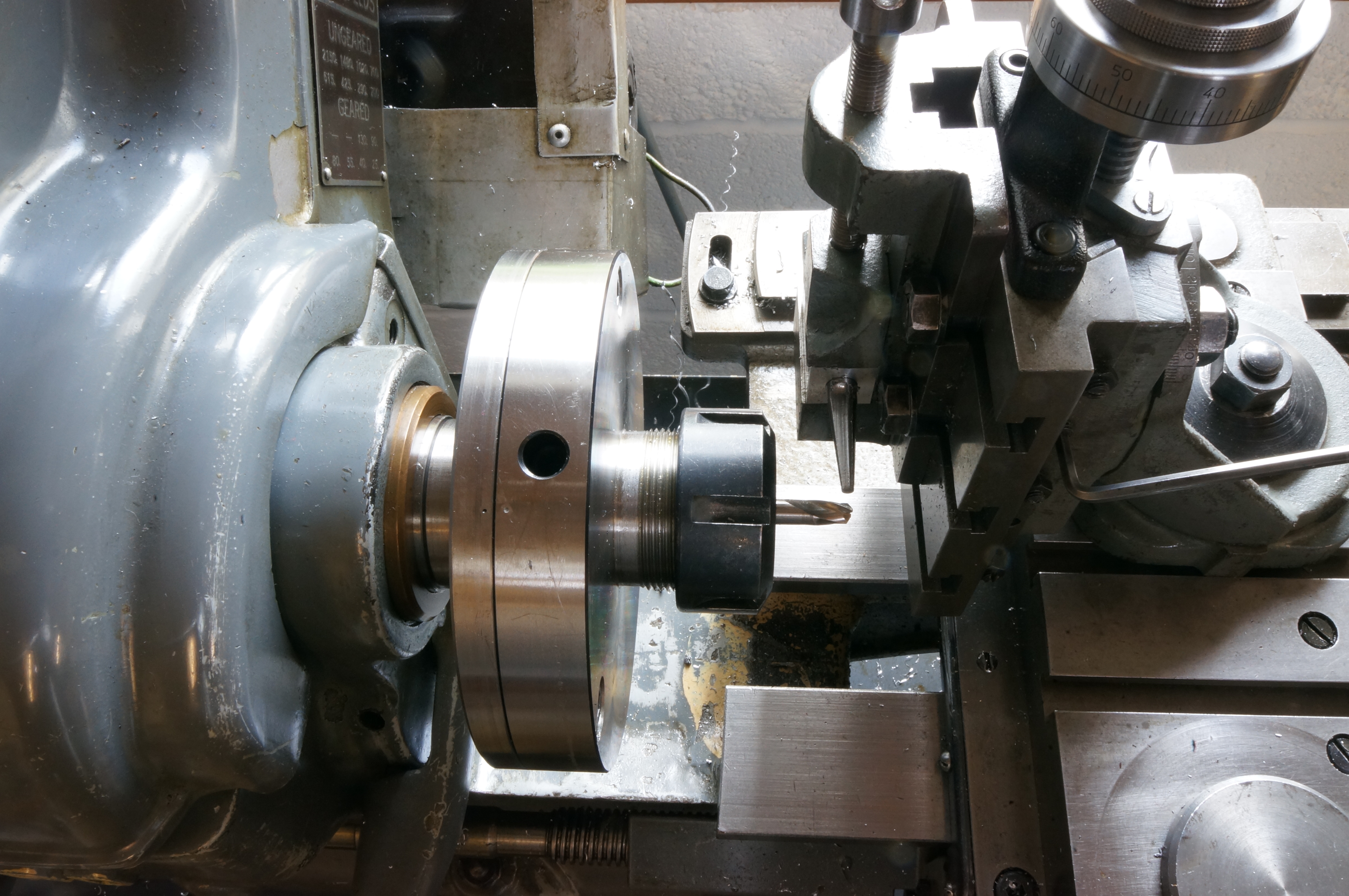
2019-04-27 - Turning the Barrel and Flange
I have decided to make the barrel in one piece, in steel rather than brass. I turned the OD to 0.4373″ and gave it a gentle rub with 1200 grit paper to 0.4371″ I roughed out the stem and then finished it to 1⁄8″. After cutting very small chamfers, I parted off and reversed the piece in the chuck and faced it to half a thou over length, to be removed after the cross hole has been reamed in situ. Checked for concentricity, and just 0.001′ out, I drilled the fuel port 2.4mm diameter, just over 1⁄16″ deep.
Turning to the flange, I used the 4-jaw to turn a chucking diameter, then held it by that diameter in the 3-jaw to machine the inside and bolting faces and locating spigot diameter. I drilled and reamed it for the barrel, which is a nice fit, and chamfered the hole to take the radius on the barrel and allow it to assemble fully. (5¼ hours)
2019-05-11 - Turning the Flange
The first job today was milling a flat on the bell-mouth radius cutter blank to form a D-bit.
In trying to set up the flange for second operation turning, I concluded I would have to waste a lot of metal off the soft chuck jaws to make a decent seating. The soft jaws are mostly used for thin pieces, so over the last few days, I have made brass sacrificial shoes which can easily be replaced.
I duly used the new jaw pieces to turn the outer face and spigot on the flange. I am not happy with the result, as a too heavy cut resulted in the job spinning in the chuck and a register diameter that is slightly the worse for wear. The material is horrible to work with anyway. I may well start again. Meanwhile I also ground a tool to cut a 3⁄64″ radius at the root of the spigot, and am happy with that looks. (est. 2 hours)
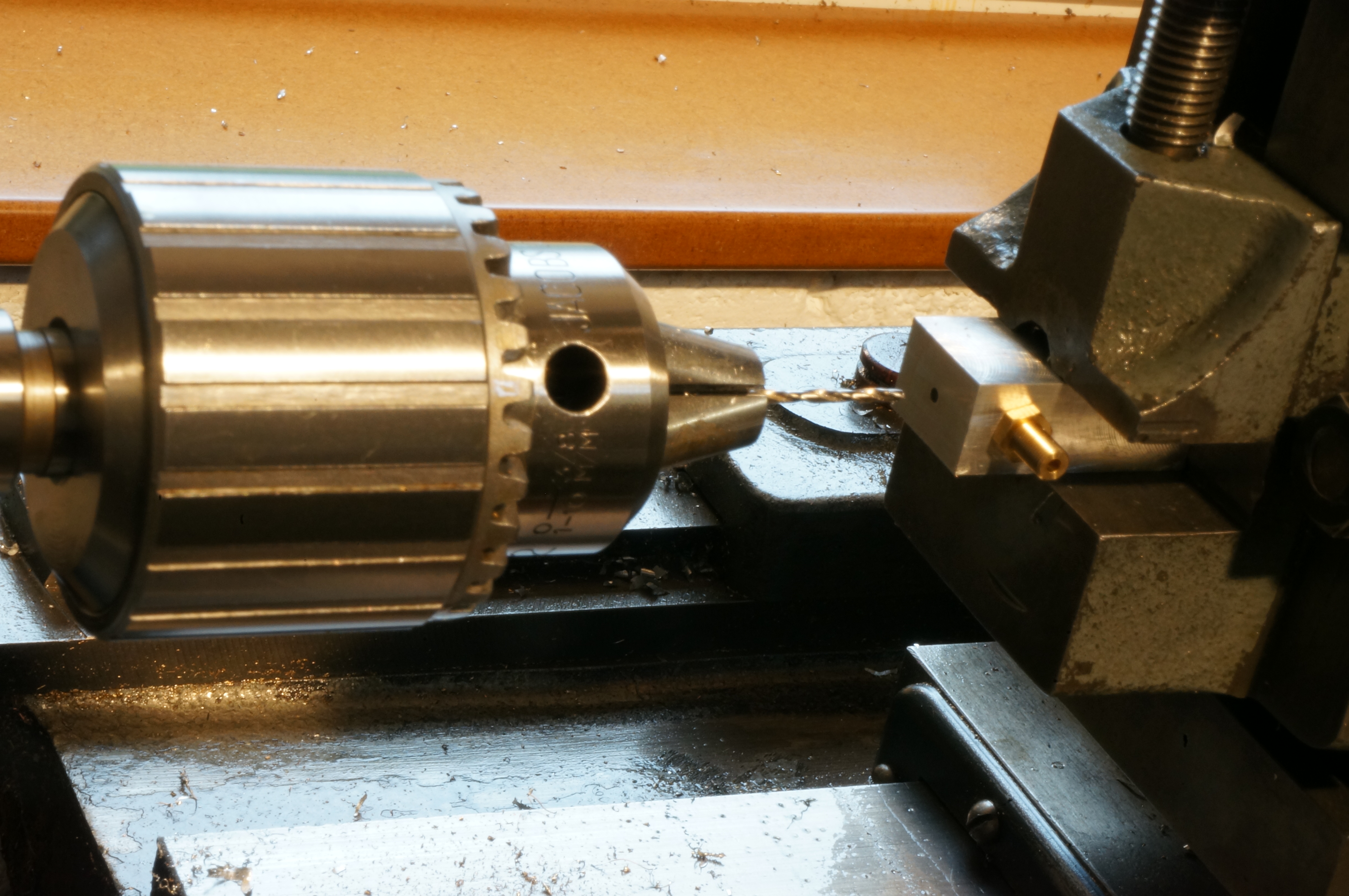
2019-05-18 - Making fuel pipe union olives
The kit includes a 3″ length of 3⁄16″ (bare) brass bar. Some of this is used for the gudgeon pin end pads, leaving quite a lot over. I used this to make some fuel pipe olives. The first one I drilled 2.4mm for the 3⁄32″ copper fuel pipe, but it is a bit loose, and I drilled the rest a size smaller. The pipe will need rubbing down a little for a fit. Having first-op turned four olives, the second operation on each was simply to face to length and turn the seating cone.
I also made a start on a new flange. This one is in (what I think is) cast gunmetal, and is much nicer to machine. I am expecting to use the same material to fabricate the final carburettor body. I completed the first and second turning operations, leaving the OD over size for milling its ears. (4½ hours)
2019-05-25 - Making a flange milling jig
Milling the profile of the flange requires rotating about three different centres. Today I made a jig to facilitate the job. This involves a plate with the centres and centring pins to locate in the rotary table. I also milled the excess segments off the sides of the flange. (5 hours)
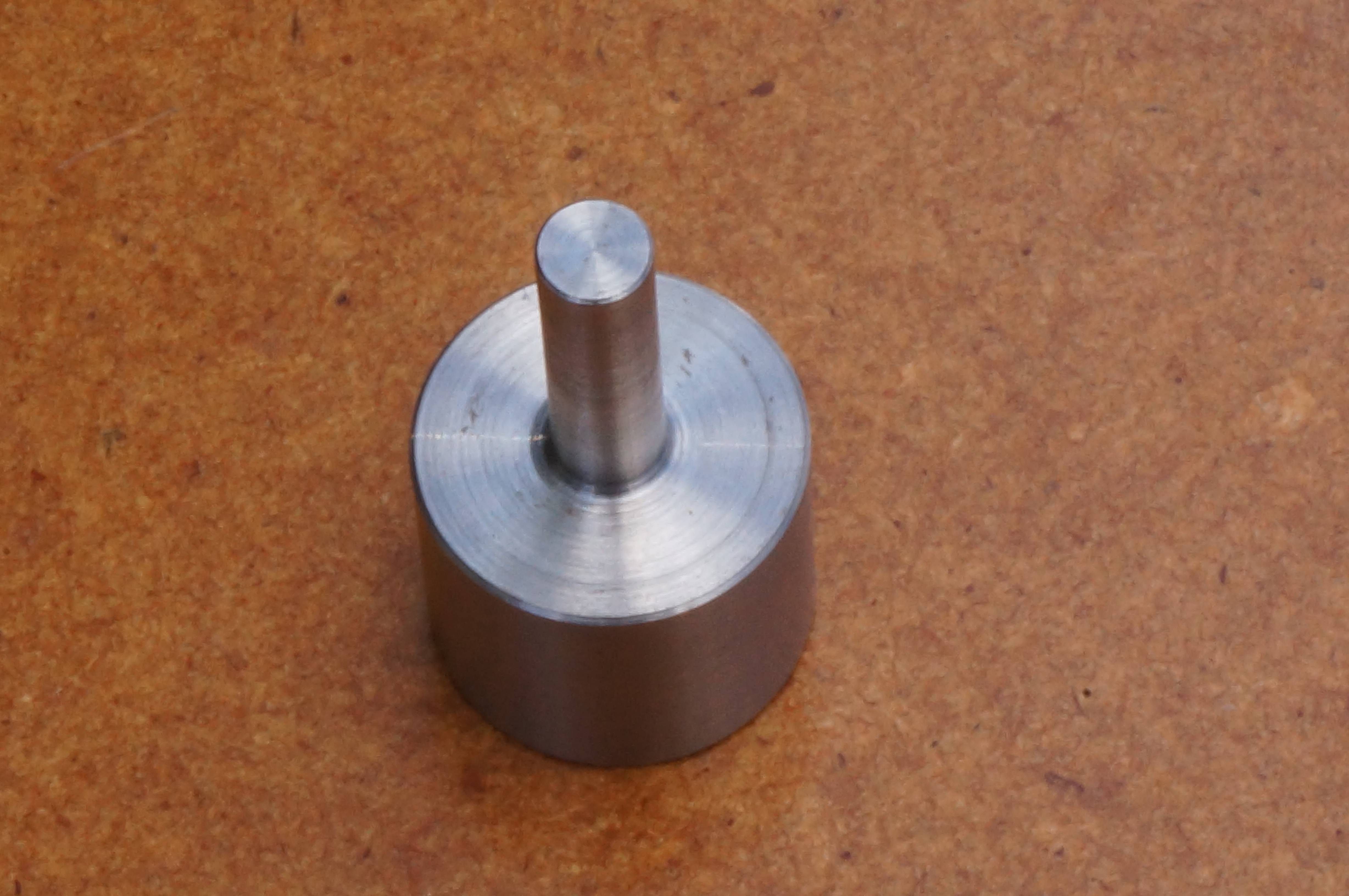
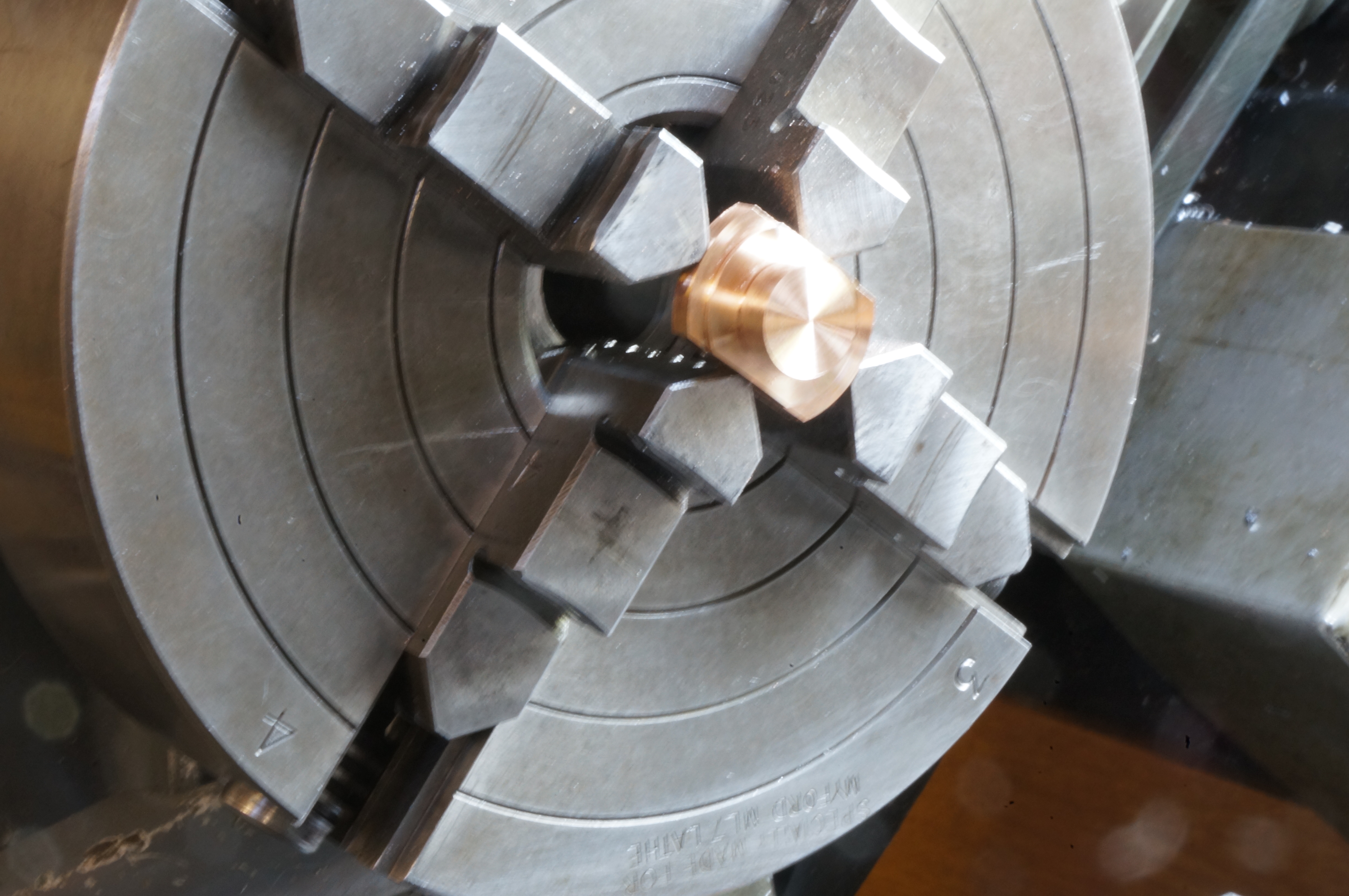
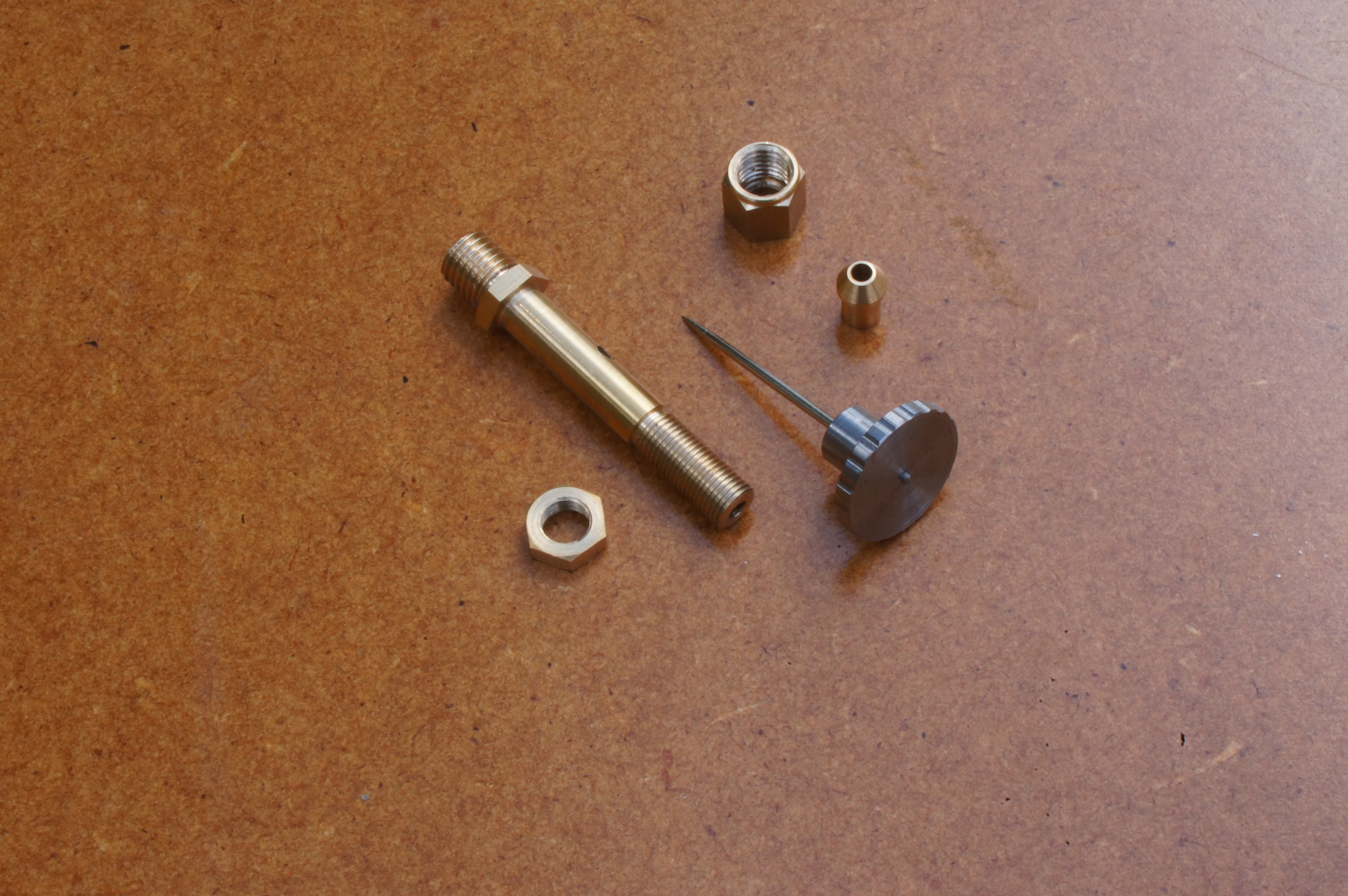
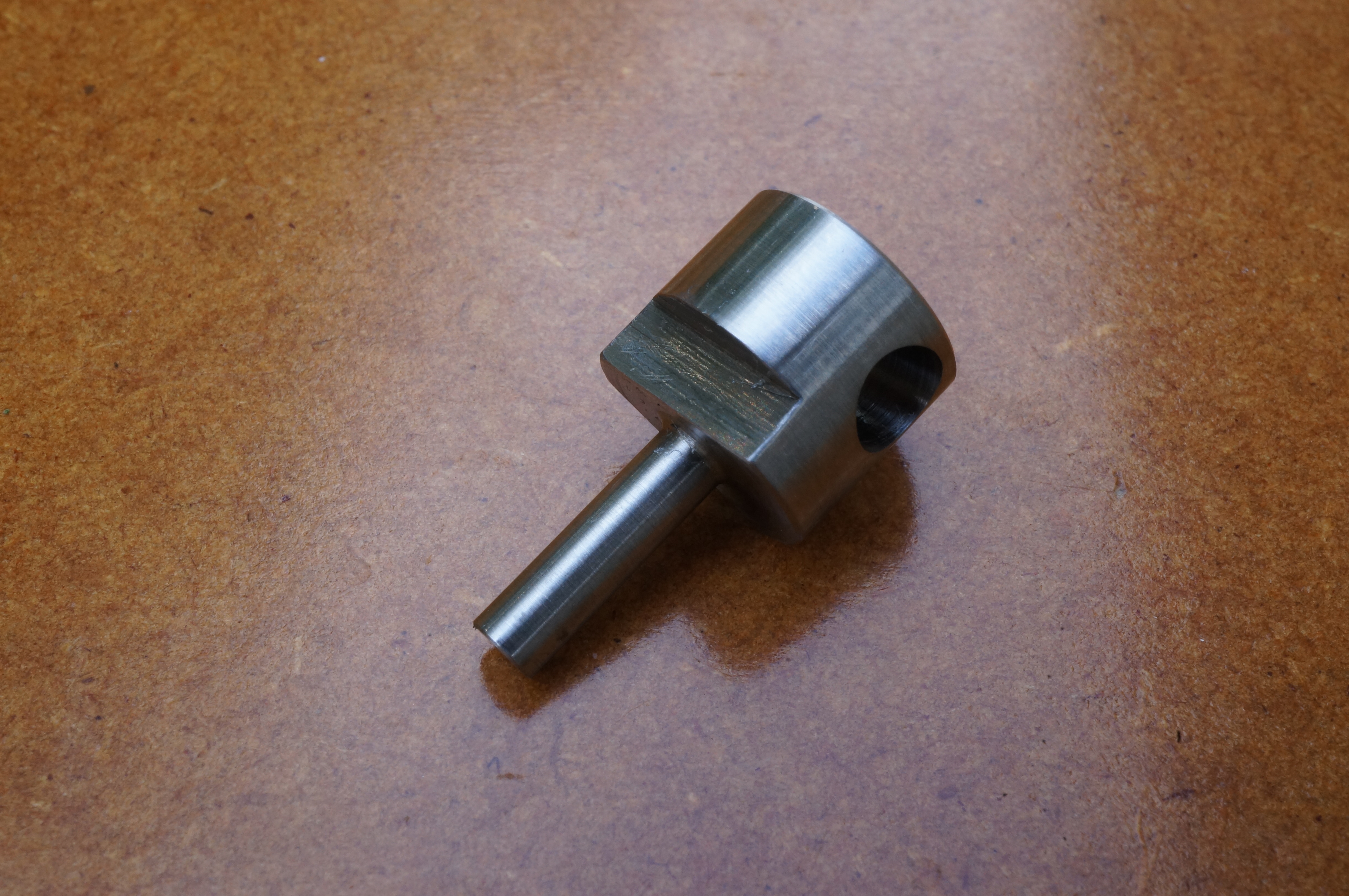
2019-06-08 - Making the Jet Knob
I faced and turned the stem diameter and drilled 3mm nearly to depth for the thread, then drilled No 65 for the needle. I opened out the hole for tapping with a 1⁄8″ slot drill, to a depth of 0.170″. I have only a plug tap in 5⁄32″ × 40 TPI, but it cut the thread OK. After grinding away the point centre at the tip of the tap, I was able to get five full turns of thread.
After parting off part way to make a groove, I transferred the chuck to the dividing head set up on the cross-slide boring table and clocked it central. With the slide set over ¼″ I started drilling 2mm holes to form the grips on the rim of the knob. I found the second hole broke into the first, so I continued drilling even number holes and then went round again to do the odd ones. (3¾ hours)
2019-06-09 - Finishing the Jet Knob
With the job and chuck returned to the lathe spindle, I turned away the ragged hole edges to form a rim that looked right by eye. The diameter is 0.013″ undersize, looks sort of OK. The grooves around the rim are disappointingly variable. I finished the parting off and faced the head to 0.066″ thick. The needle does not quite go in. With the hole redrilled No 65, the needle would perhaps go in if forced, but opening one size to No 64 it fits well. (½ hour)
2019-06-17 - Making another one
I have discovered Tracy Tools could supply a 5⁄32″ × 60 TPI tap. Change of plan. I made a new knob by much the same method but with the finer thread, using a 3.5mm end mill to cut the tapping size hole. For the rim of the knob, I turned it to finished diameter first and milled the scollops with a 2mm end mill. The result was much better.
The kit includes a 2″ length of hexagon brass bar 0.248″ A/F for 4-BA, for the jet tube. The drawing shows 7⁄32″ A/F, which is close to 5-BA. 5-BA hexagons (0.220″ A/F) will look neater. I milled the bar in two passes on each flat. The large projection from the chuck was a little alarming, but it went fine. At 0.222″ A/F at the tip end, a 5-BA ring spanner fits. I parted a 1¼″ length, including the untouched chucking piece, for the jet tube.
From the remaining piece I made the nut that holds the jet tube in place. The remnant will also be used for fuel pipe union nuts. These nuts will need a tiny internal undercut at the bottom of the thread, and I started work on a boring bit, using one of my previously prepared 3⁄16″ silver steel blanks, and turning the stem down to about 3⁄32″. (5½ hours)
2019-06-22 - Hardening tools
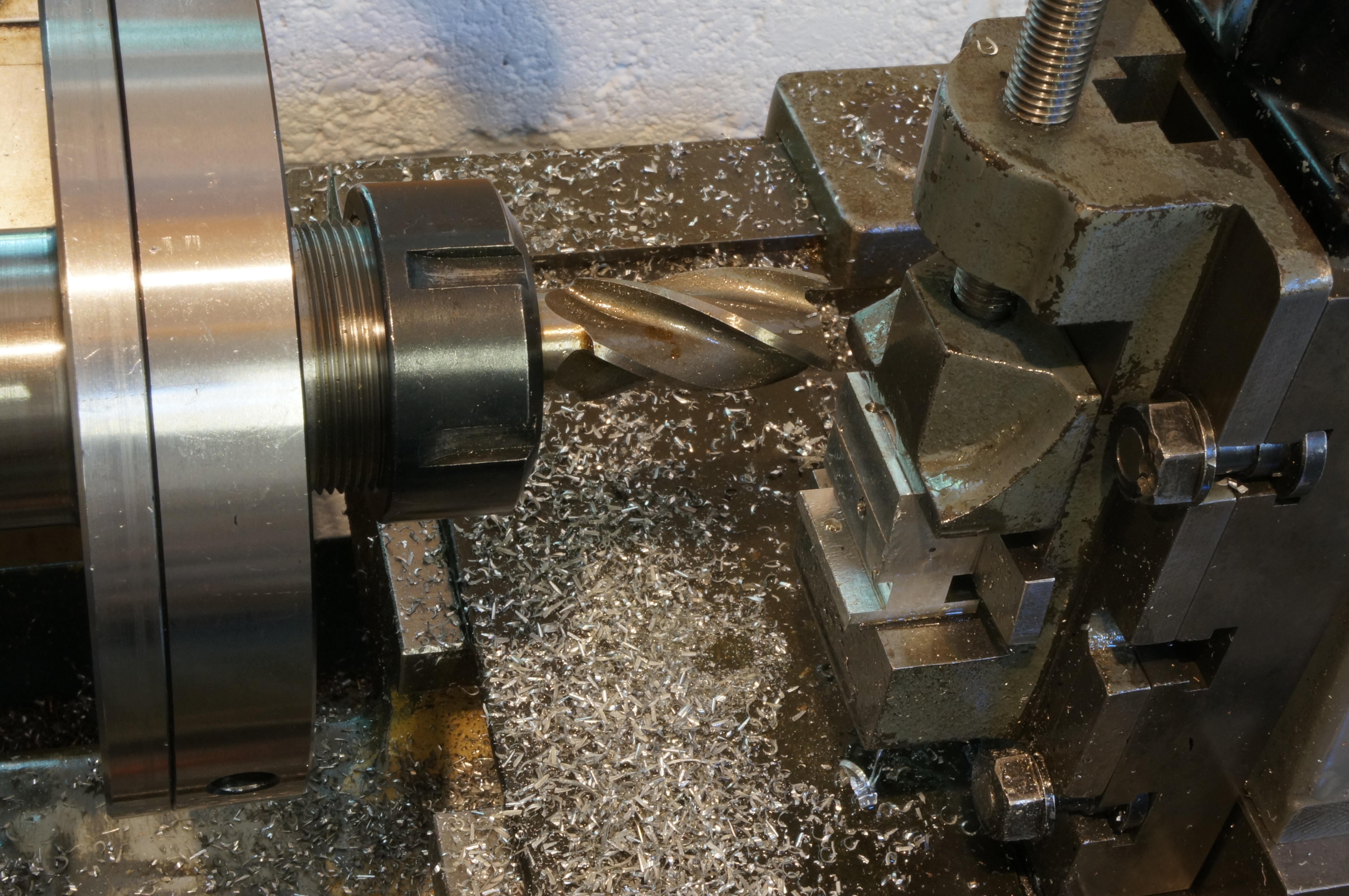
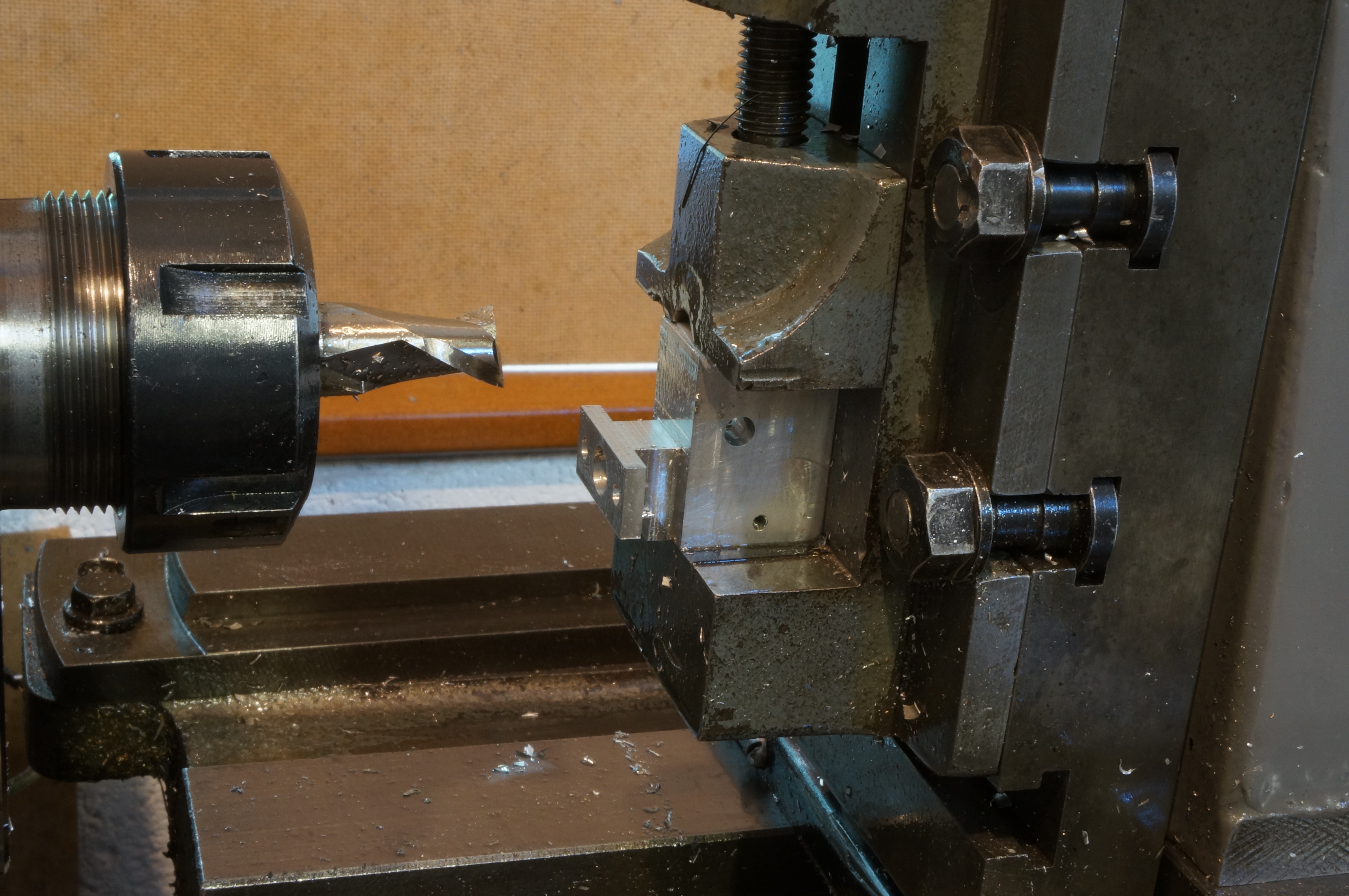
Having finished the shape of the undercut boring bit by filing, and filing reliefs on the valve seat cutter that I machined a while ago, I was ready for a hardening session. As well as these two tools I also hardened the reamer for the throat taper and the D-bit for the intake flare radius. I tried the latter tools on a short remnant of ½″ aluminium bar to make a dummy draught tube. Both tools cut nicely if not forced.
I was surprised, as is anyone else who tries it, by the fluid mechanical effect of the bell-mouth entry and tapered diffuser. If you put the test piece between your lips and blow through it, and then turn it round and blow the wrong way, into the taper and out of the flare, it very apparent how much easier it is to blow the right way.
I also did the first op. turning on a pair of fuel pipe union nuts. External turning of shoulders will need to be done on a mandrel, they are so small. (4 hours)
2019-07-02 - Turning the Jet Tube
Having faced off the end of the milled hexagon bar I set it to run true with enough projection for turning the screw end. First I tried a 0.01″ cut without tailstock support, but that produced a 0.003″ taper, so yes I do need tailstock support. I used my home-made small running centre, but still needed to grind a tool to get close in. With another light cut the taper reduced to 0.001″. I finish turned it to 0.1564″ at the outboard end and 0.1561″ at the chuck. (2 hours)
2019-07-06 - Scrapping the Jet Tube
First I drilled the jet tube at the jet end, with the little hole going nicely. The I set up for screwcutting. For the 60 tpi thread I should be able to engage the half-nuts at every other turn of the leadscrew. Using just the numbered positions (every fourth turn) I was surprised that the second cut mangled the the first. I think I carried on using the same position on the dial until I had a ropey thread cut somewhat over depth. The nut started nicely but did not want to go any further. After some head scratching and sanity worry, I found the problem. I could hardly expect a 60 tpi nut to to go onto a 75 tpi jet tube. I had made a mistake with the change gear train. I will use this one for a practice run at drilling the No 70 jet. (Thats 0.028″ or 0.71mm.) I also need to improve the tip of the screwcutting tool.
I turned a piece of 3⁄8″ brass bar to 0.270″ for a 17⁄8″ length and parted off. I milled the 5-BA hexagon over an inch length of this piece, getting rather more variation in the resulting A/F dimension than on the first piece, varying from 0.2185″ to 0.2215″. Rather more than I would like, but acceptable.
I then spent some time regrinding and honing tools: a zero rake bit for turning and facing, with a tip radius of about 0.010″ and a 55° threading tool with an accurate sharp point, and putting a flat on the tip about 0.003″ wide. (5¼ hours)
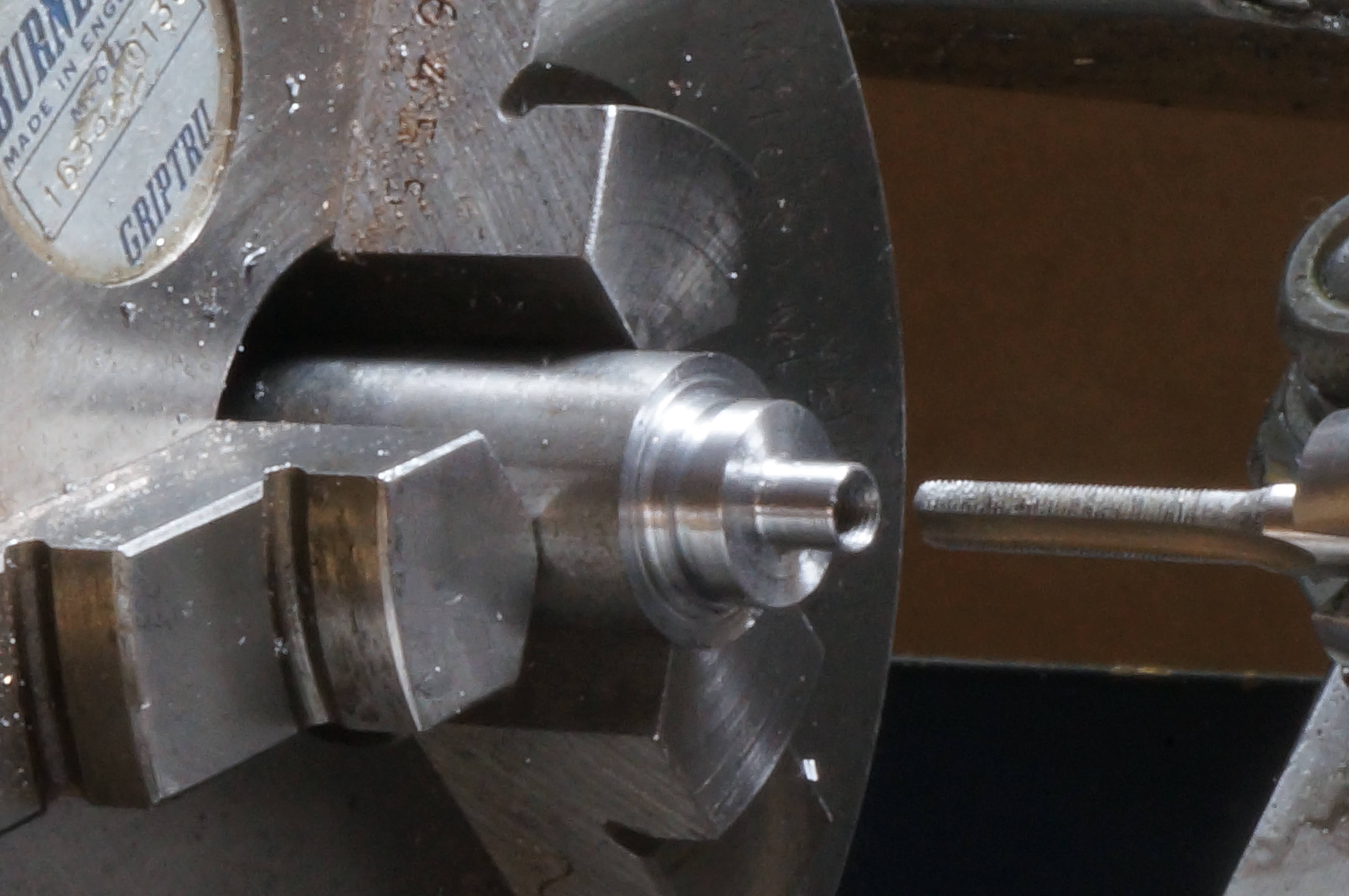
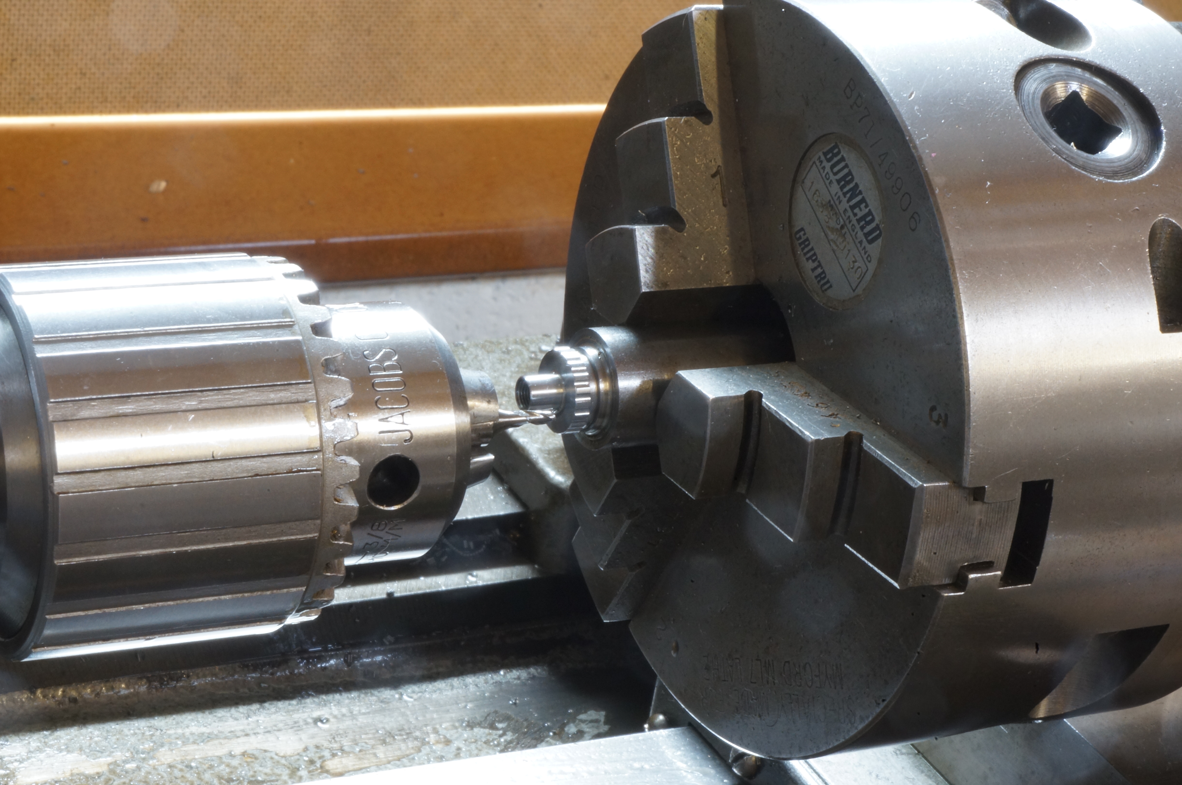
2019-07-15 - Threading the Jet Tube
For turning the jet tube I need to use the extended toolholder and a straight tool relieved to clear the centre. This means a very short front edge on the tool and a difficult job honing a radius. With the jet tube clocked true in the Griptru chuck I found after a couple of cuts I still needed to grind more clearance a the back of the tool. Turning close to a shoulder at top speed, even with a very fine auto feed, felt too hairy, and I dropped down to 1500 rpm. I ended up with the tube 0.1564 ″ at the outboard end and 0.1562″ at the chuck, which should be a nice fit in the 5⁄32″ reamed hole in the carb body.
I reduced a length of just less than 3⁄8″ to 0.1545″ diameter to truncate the thread crests, as I do not have a 60 tpi chaser, and want to be sure the jet adjusting knob is sitting on the thread flanks. In spite of taking the first cut with the toolholder not clamped, the thread turned out well this time. I carefully drilled the 1.6 mm hole for the needle to 0.696″ point depth, as measured on the tailstock dial, to give the correct final11⁄16″ depth to the shoulder of the jet hole.
I parted the tube off and set it running true for the second op turning at the other end. I faced the end to length and turned a 3⁄16″ diameter for a 3⁄16″ length. I chamfered the hexagon and the thread end, and made a thread run-out undercut. I screwcut the thread for the pipe union, and finished it with a chaser. I used a centre drill to form the conical seat for the pipe union, the drilled the 1.6mm hole and the No 70 jet hole.
I rubbed the hexagon flats on a union nut to remove the tool marks. With the jet tube nearly complete, I was able to find the correct position to Loctite the 0.035″ diameter sewing needle into the jet knob, leaving the eye end of the needle to be cut off later. While cleaning up I caught the No 70 drill, still in the tailstock, with the back of my hand and snapped it. An irritating end to an otherwise successful session. (5¼ hours)
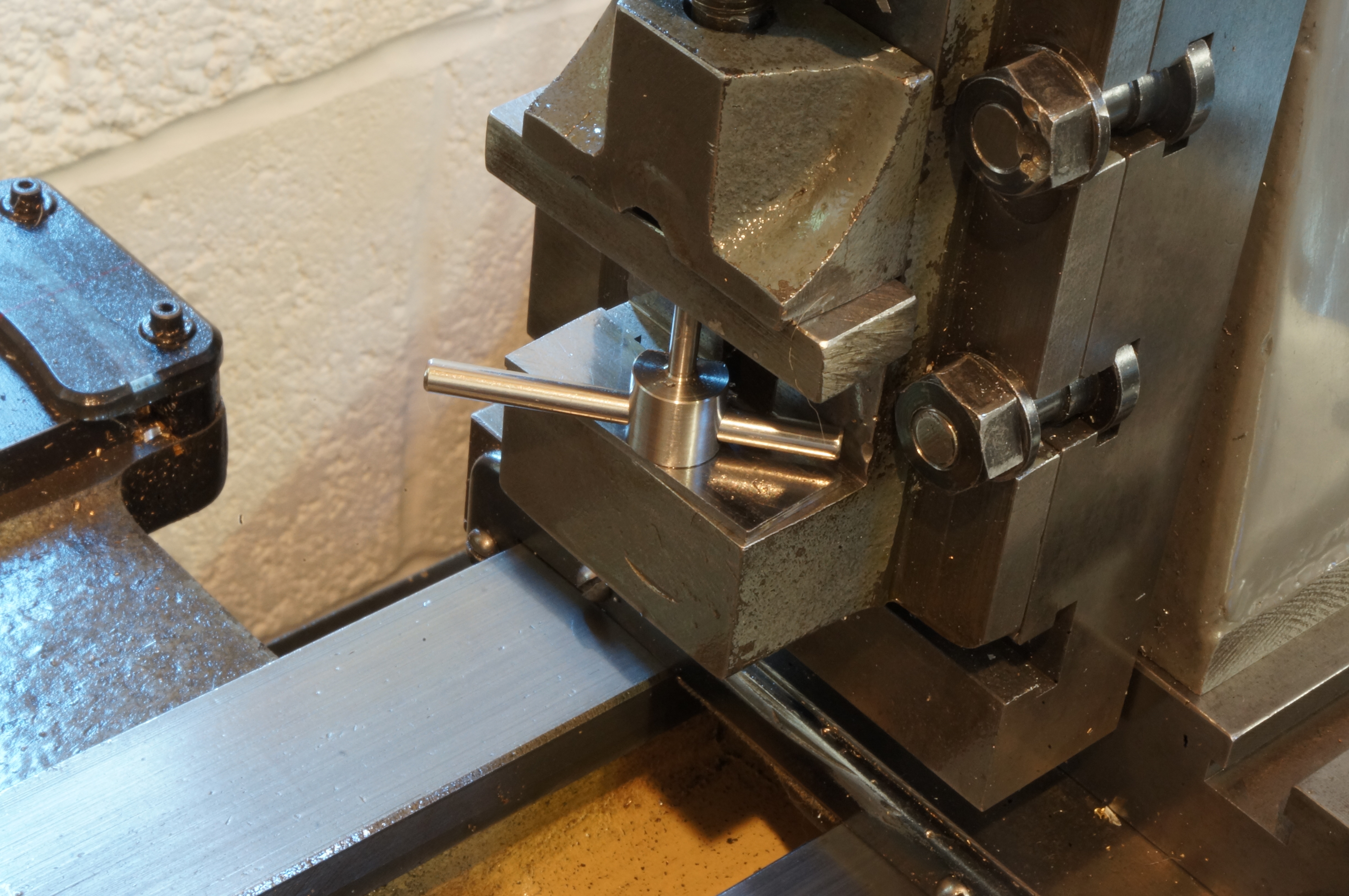
2019-07-27 - Cross-drilling the Jet Tube
With the lathe already set up for milling an unrelated job, I made a rectangular jig block for cross drilling the the jet tube. I drilled and reamed the hole for the tube 5⁄32″ then set the block at 90° and offset one face sideways by 5⁄16″ to give the correct position for the cross hole. With the Jet Tube in position and held by its nut, I drilled the 1.6 mm cross hole.
Next, I set up the flange and drilled the mounting holes 2.2 mm. Actually, I found a 2.18 diameter pin would not enter the holes. I think the drill must be worn. (3¼ hours)
.
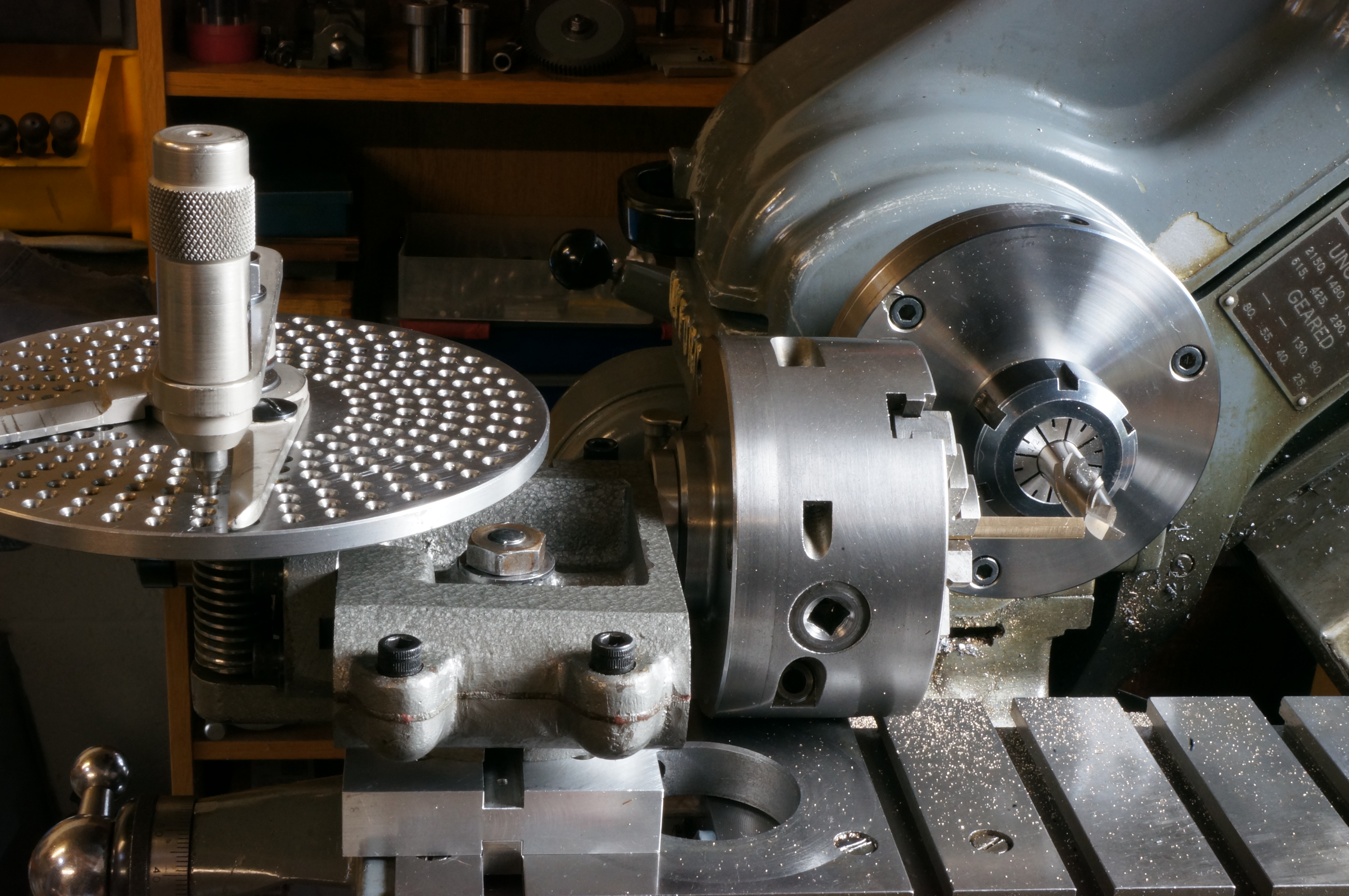
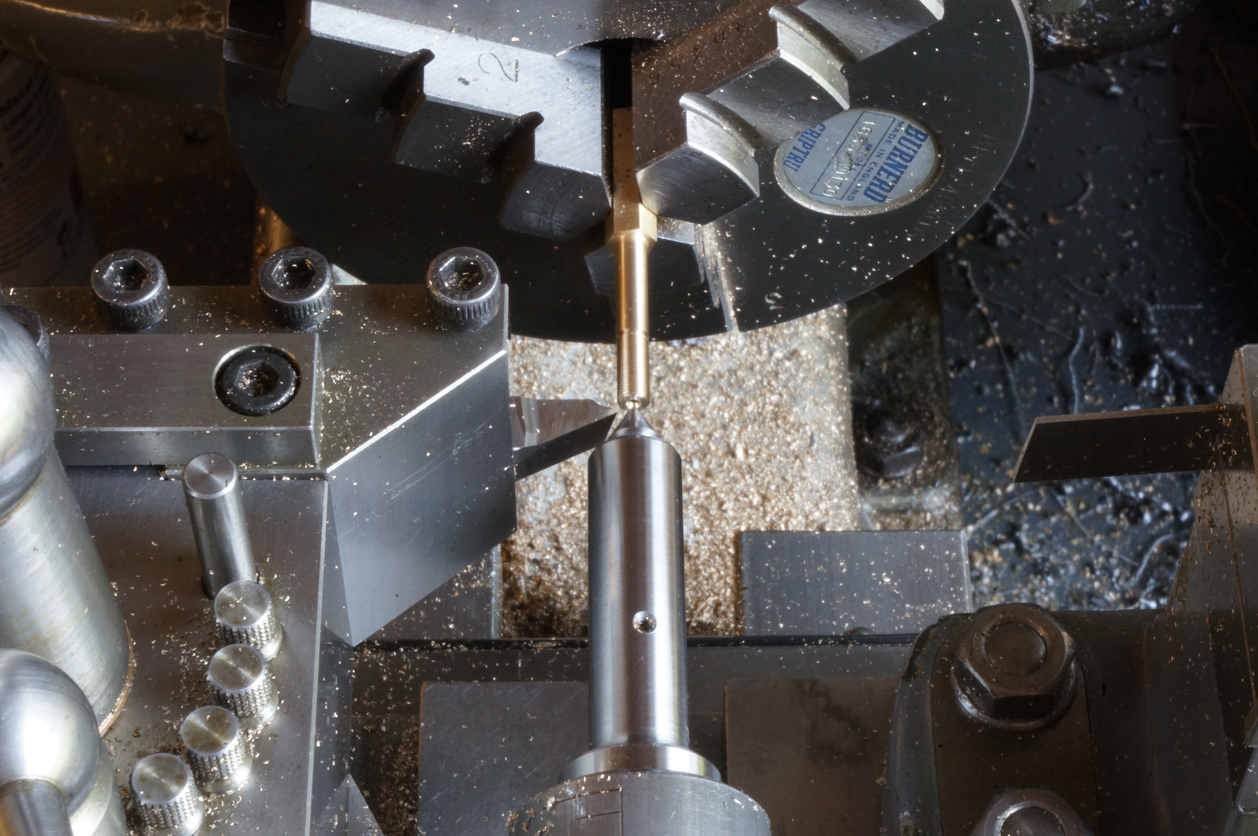
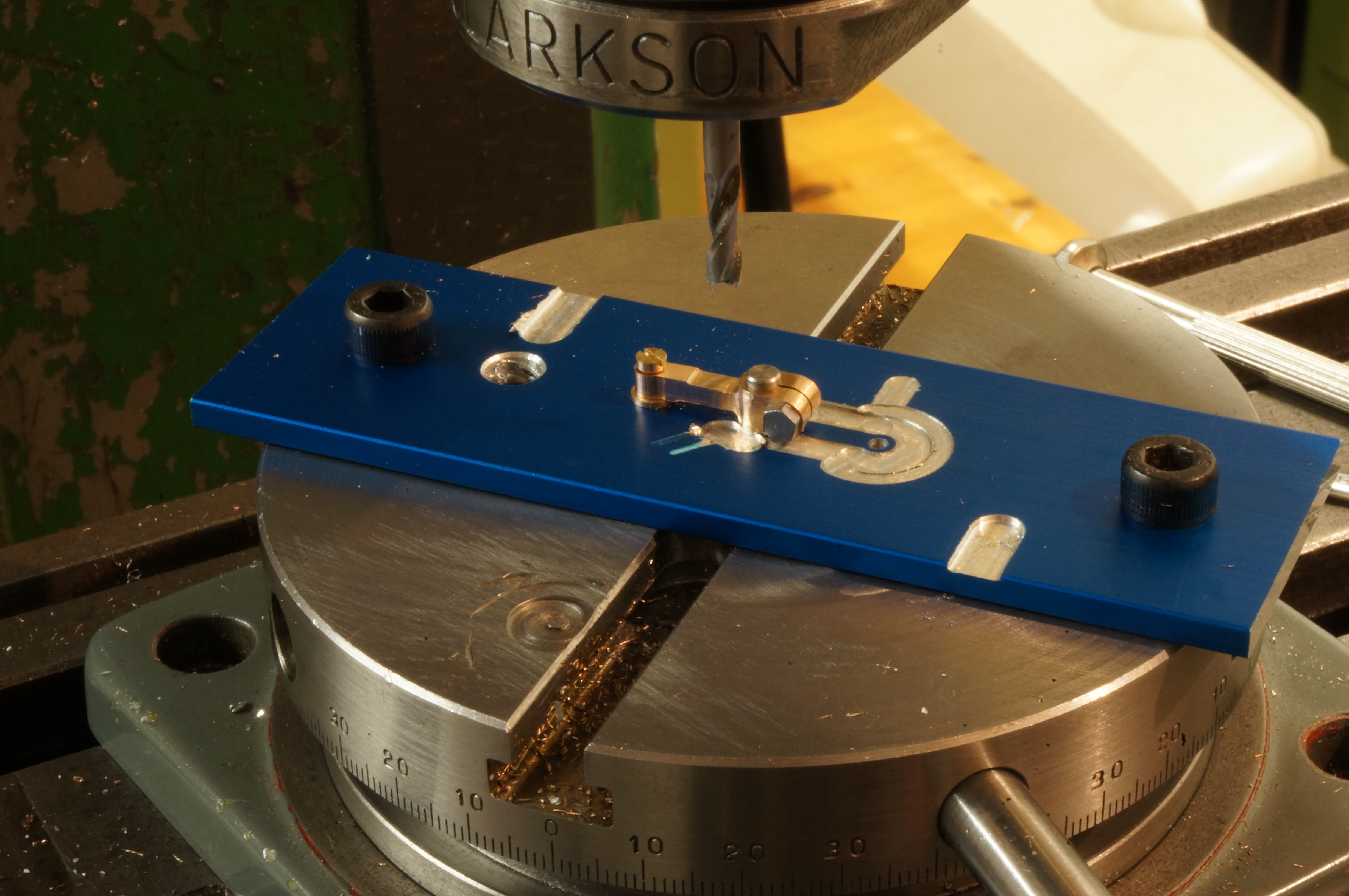
2019-08-04 - Profiling the Flange
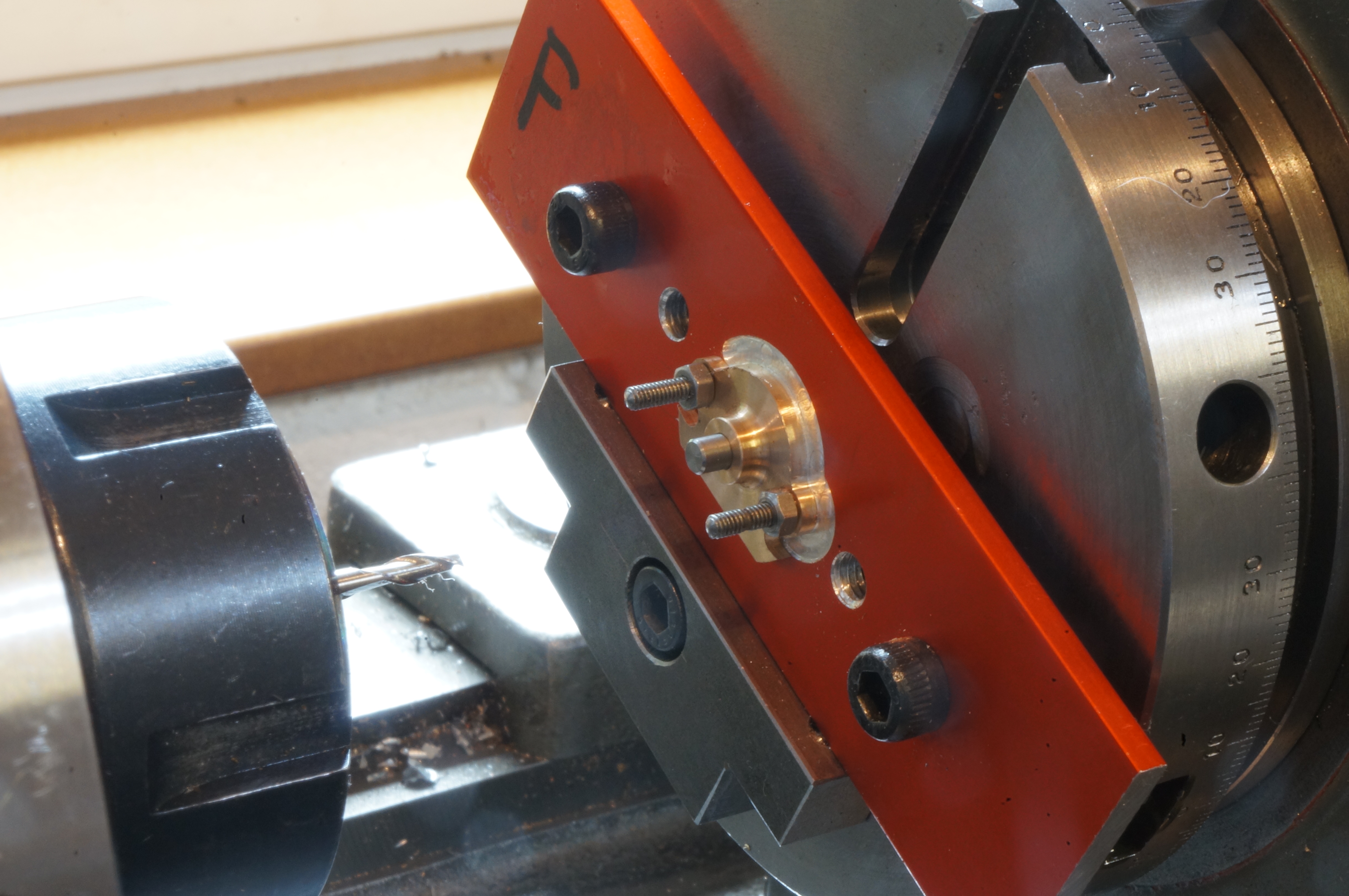
The first job today was to open the flange mounting holes to 2.3 mm.
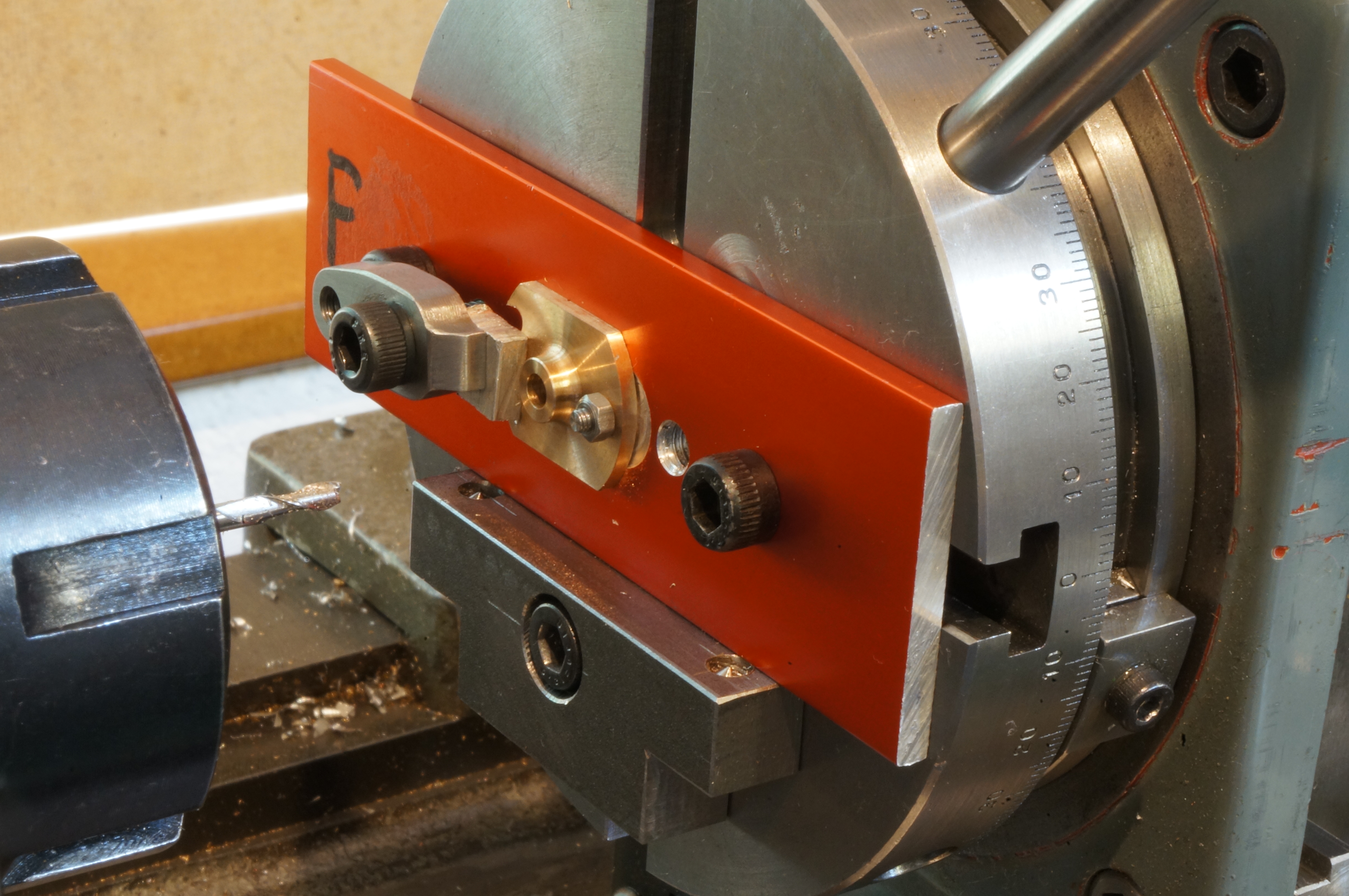
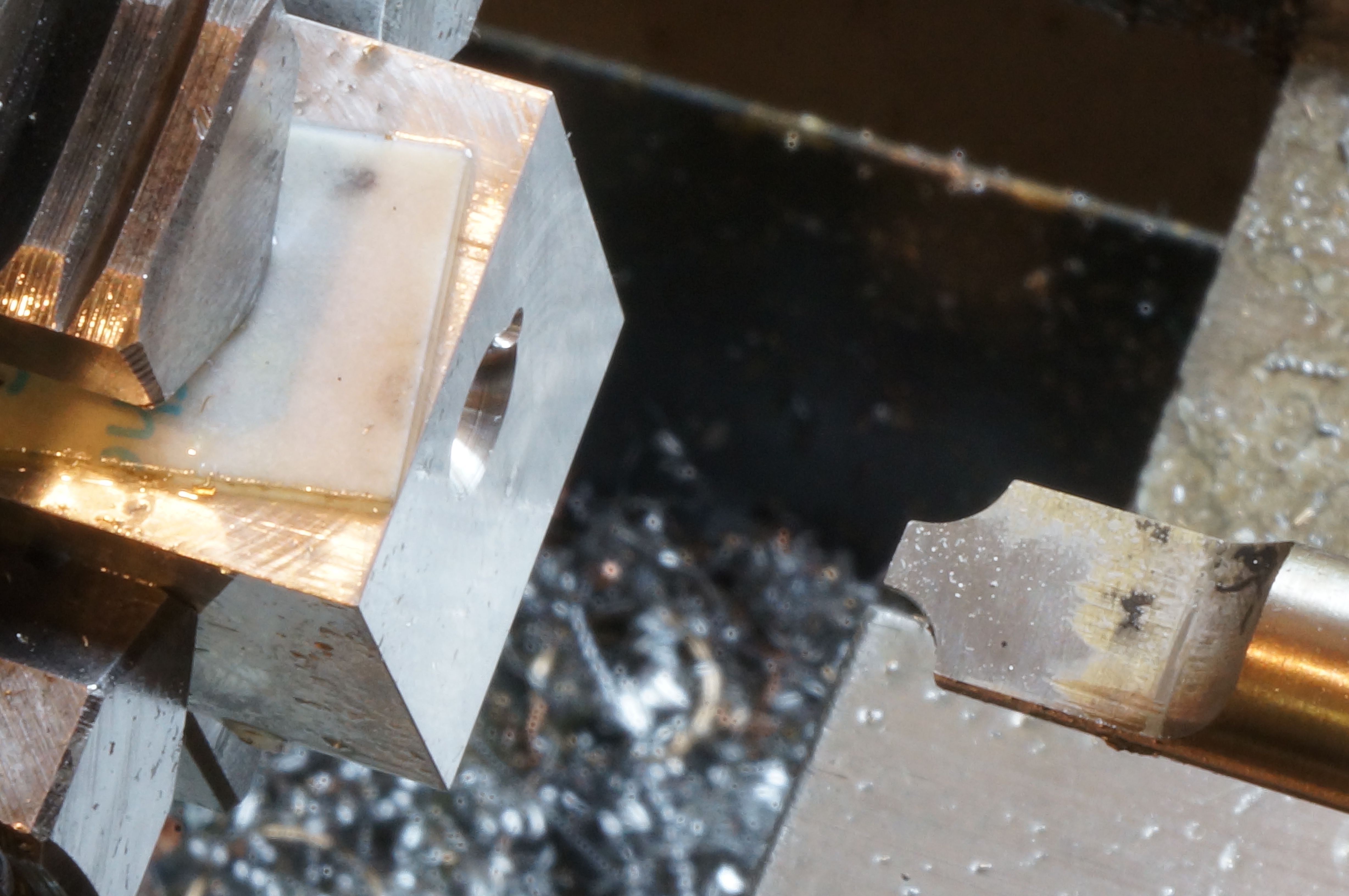
The flange profile requires milling four arcs around three different centres. With the rotary table centred, the flange holes are located on centre by fitted pins in the central hole of the rotary table. The guide block under the red jig plate allows the plate to be easily repositioned for each arc while maintaining the same angular position on the table for all.
In the first photo, one of the 'ears' has already been milled, and the job has been repositioned for the other one. Using a 3⁄32″ cutter to mill a 3⁄32″ radius requires a 9⁄64″ (0.141″) offset. Initially I offset the table 0.150″ horizontally and set the stops for 90° swing either side of horizontal. I took cuts 0.020″ deep, using the leadscrew handwheel. Once I had milled to depth, I reduced the offset by 0.009″ and took a finishing sweep round the ear. I ran the cutter at 1500 rpm.
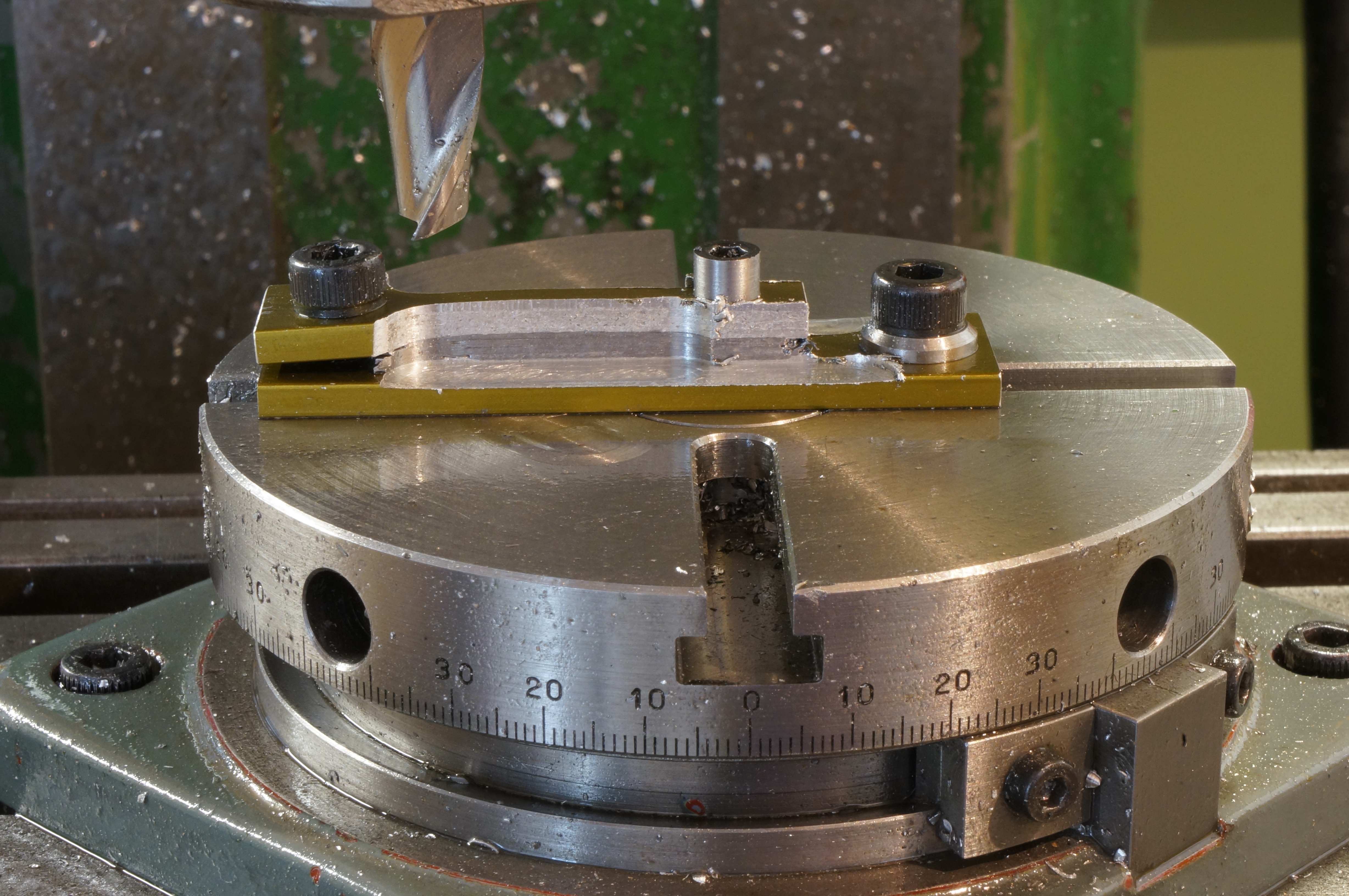
For the flanks, the table is re-zeroed horizontally and lowered 0.335″ for the initial cuts. The jig is repositioned to centralise the flange on the table, and the table stops set to allow 64.5° swing either side of vertical. For the final cut the vertical offset is reduced to 21⁄64″ to produce the 9⁄16″ flange diameter. (est 2¾ hours)

.
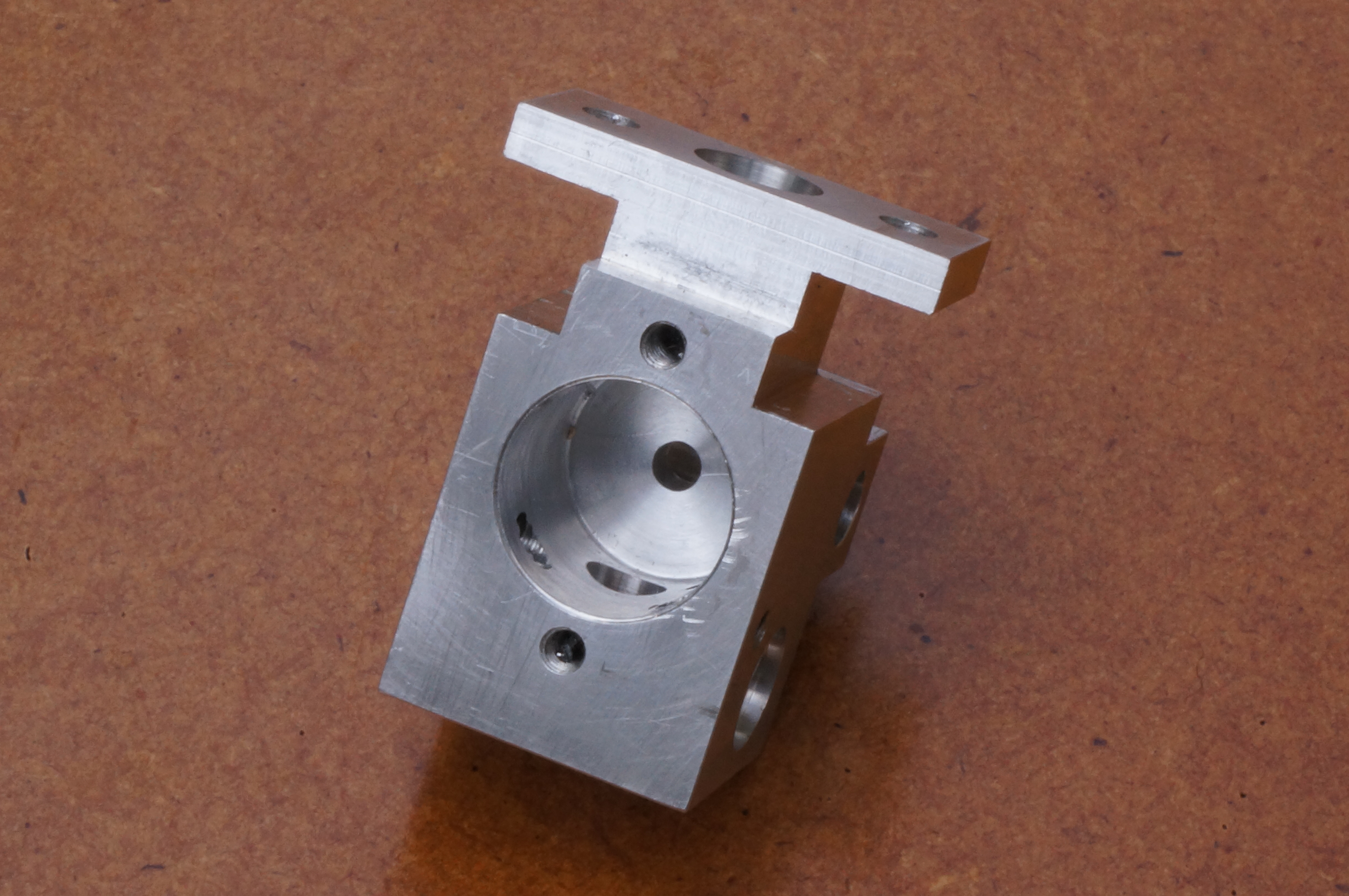
2019-08-12 - Drilling the body
Even this clunky first try carburettor body is a quite complicated machining job, and definitely one where a carefully thought-out sequence check list is needed.
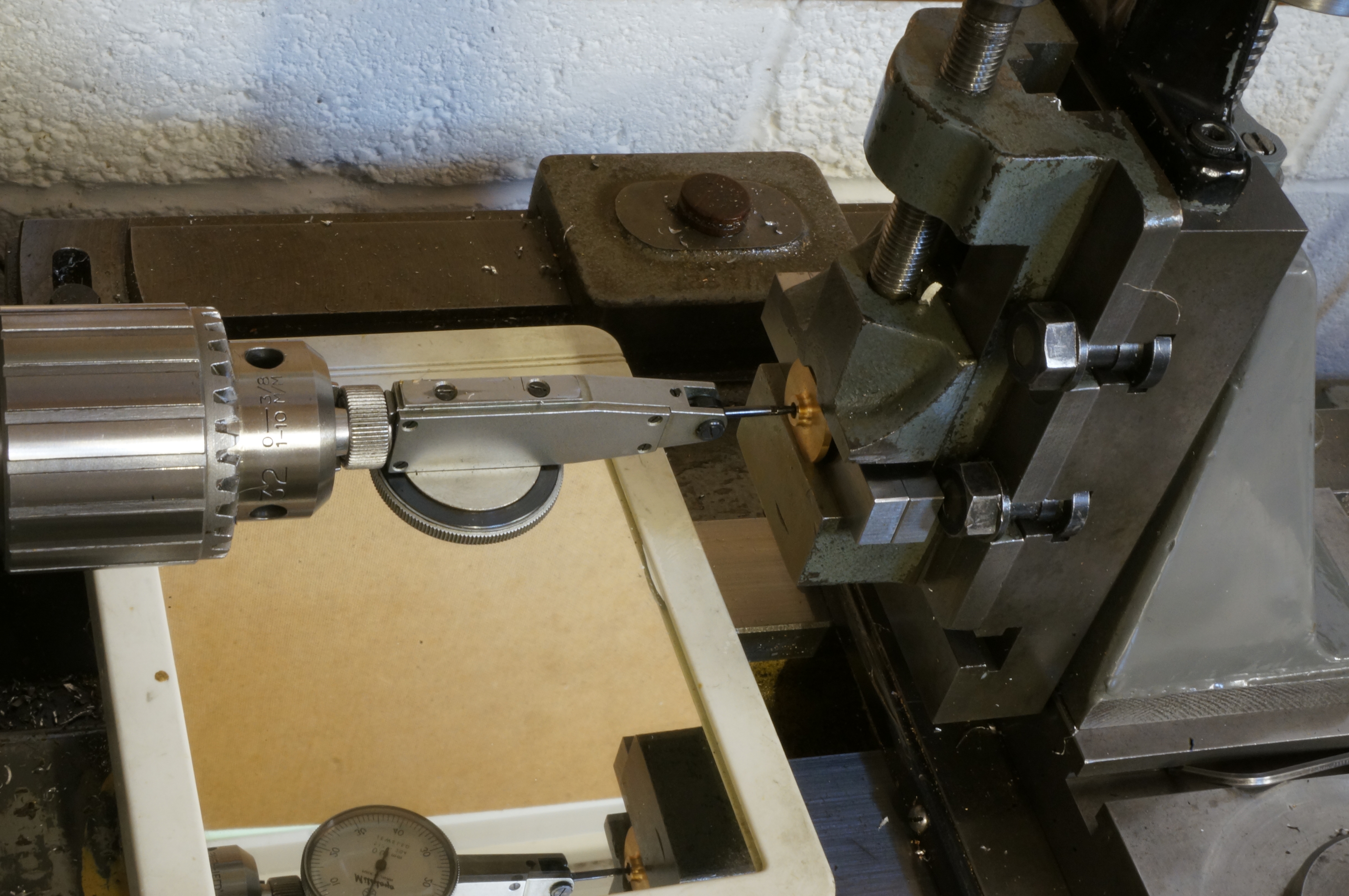
The arrival today of a new 2.2mm drill allowed the holes for the flange studs in the carburettor body to be drilled and tapped. Still using the vertical slide in the lathe, I also drilled a 6-BA tapping size in the front for a toolmaker's button for the barrel hole and drilled and reamed the 5⁄32″ hole for the jet tube. After tapping the holes, I set the toolmaker's button in the correct position for the barrel hole, in the usual way with gauge blocks on the surface plate. (2¼ hours)
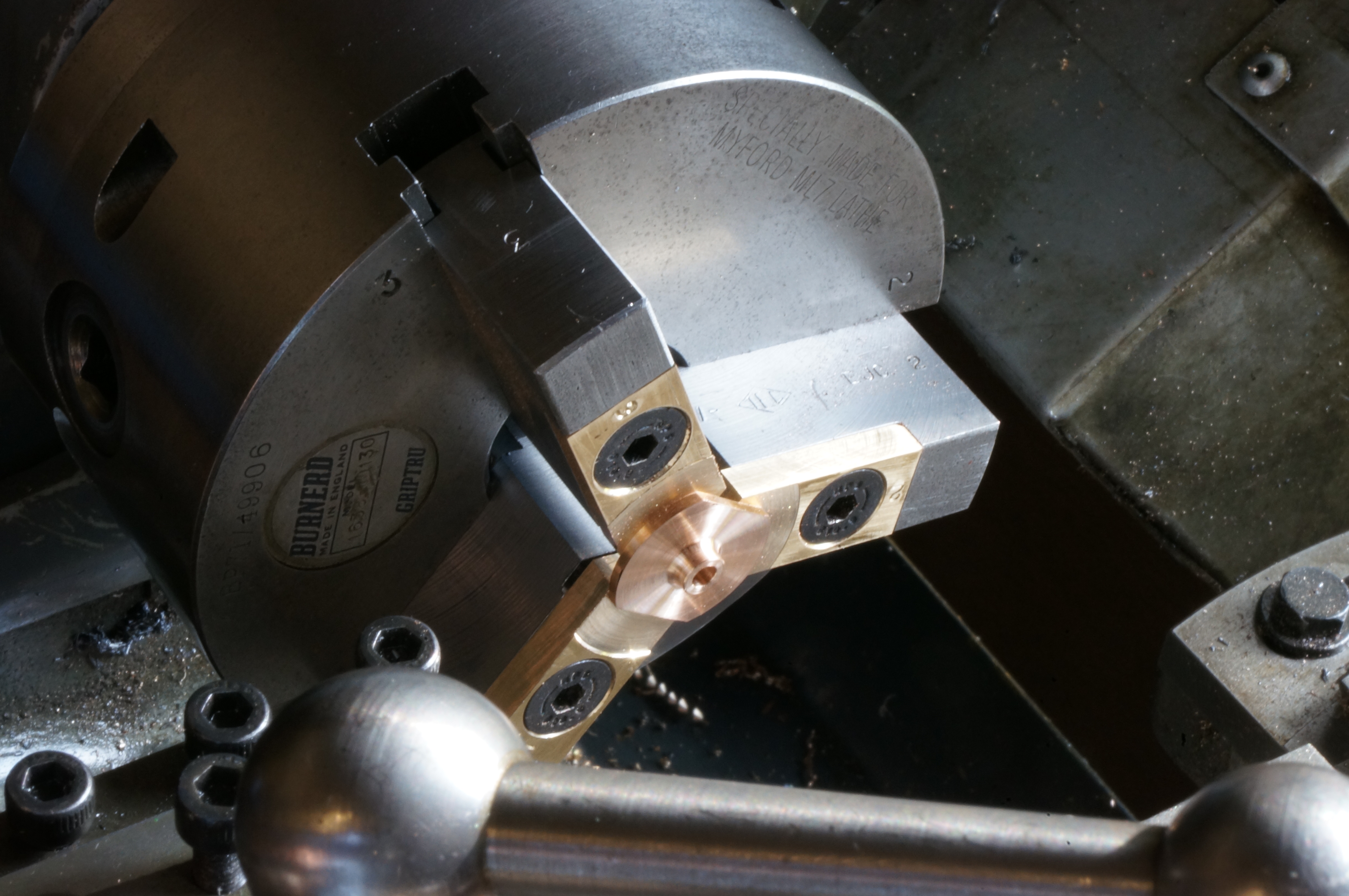
2019-08-16 - Boring the barrel hole
Today I tried turning by eye the tiny ball end of the throttle lever. It was rubbish. I don't much like the shape of the original design anyway.
Back to the carb body. In the 4-jaw chuck, I managed to get the button running dead true. I roughed the barrel chamber with a 3⁄8″ slot drill, then centre drilled the bottom of the hole, drilled the fuel port 2.1mm through to the jet hole and opened it to 2.4mm. After checking the topslide was set pretty parallel by clocking against the tailstock barrel, I bored out the chamber to a nice fit on the barrel, and to a depth of 7⁄16″ plus one thou. I am happy with that, so far. (2¼ hours)
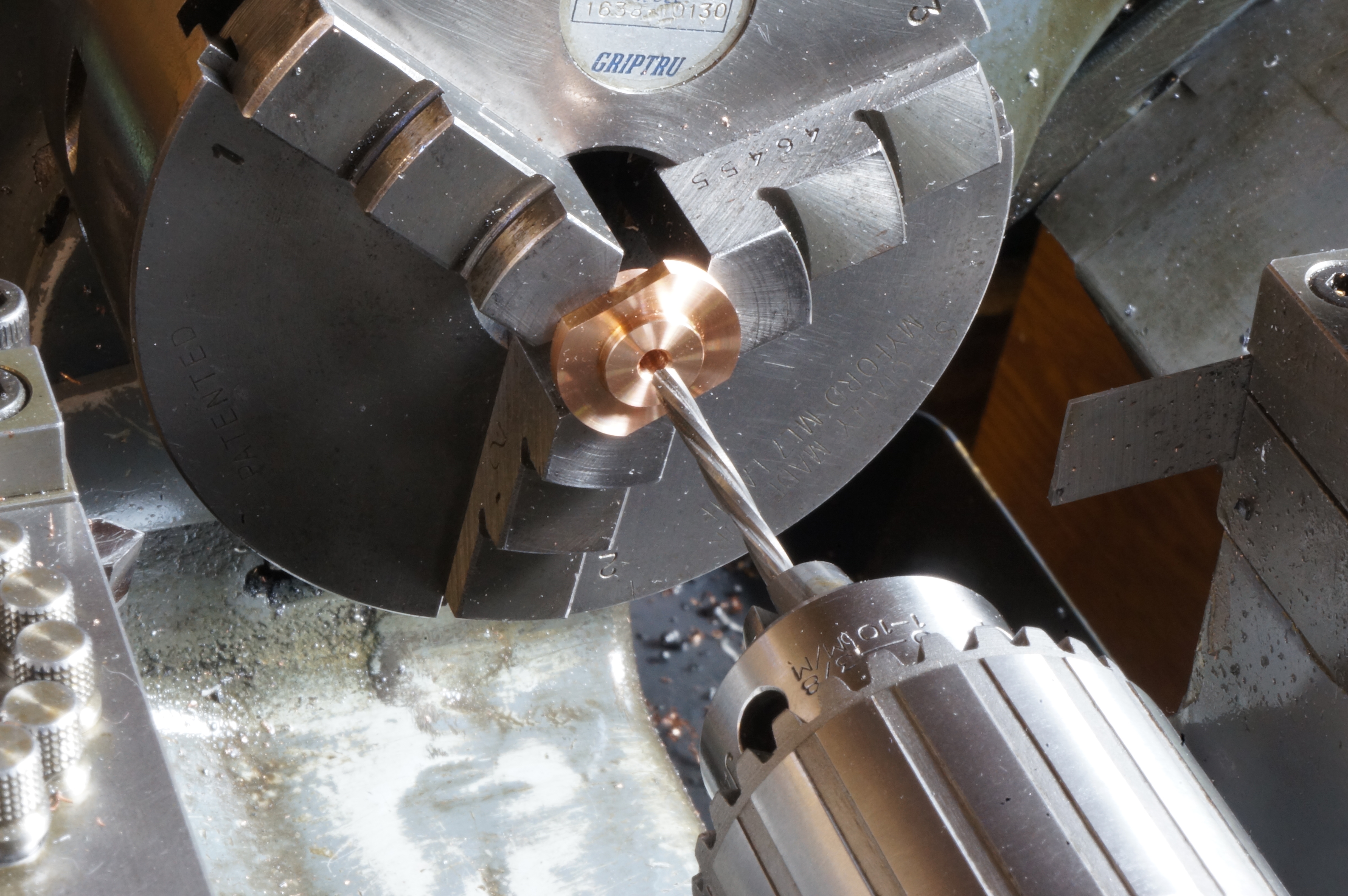
2019-08-17 - Boring the venturi
I started by drilling the air bleed hole from the back of the body through to the jet tube, and the slow running air hole from the bottom, into the barrel chamber.
The next job is to put the venturi hole through the body and barrel together. I located the barrel with a thickness of cigarette paper behind and of notepaper in front, clamping it in place with the flange. With the block eventually clocked square and correctly positioned, I drilled and reamed the 5⁄32″ choke hole, and reamed the venturi exit taper with the previously made reamer. I used a ¼″ ball to gauge the hole. The taper geometry requires a projection of 0.130″ for a dead-on ¼″ exit diameter. I got 0.123″, so 7 thou deep. Fortunately then, I did not need to take any more off, because I found I could not get the ball out of the hole without disturbing the set up, not even with a magnet. While the body was set up in this position, I drilled the 2.8mm mounting flange holes. A tap with a drift from the other end was needed to get the ball out.
The next thing was the barrel stuck in the bore, presumably by slight burring of the venturi hole edges. While considering what to do over a mug of tea, it occurred to me to give the job one too. After a dunk in boiling water the barrel came out easily. After gently deburring with 1200 grit paper and working the parts together with some oil, the barrel turns OK, and with the flange bolted up. (4¼ hours)
2019-08-18 - Finishing the choke bore
With the body set up again in the 4-jaw, with the choke hole clocked true, I cut the bell-mouth with the previously made radius D-bit. I also drilled and tapped the 8-BA holes in the sides for the throttle stops, and in the bottom for the choke (strangler) plate. (2½ hours)
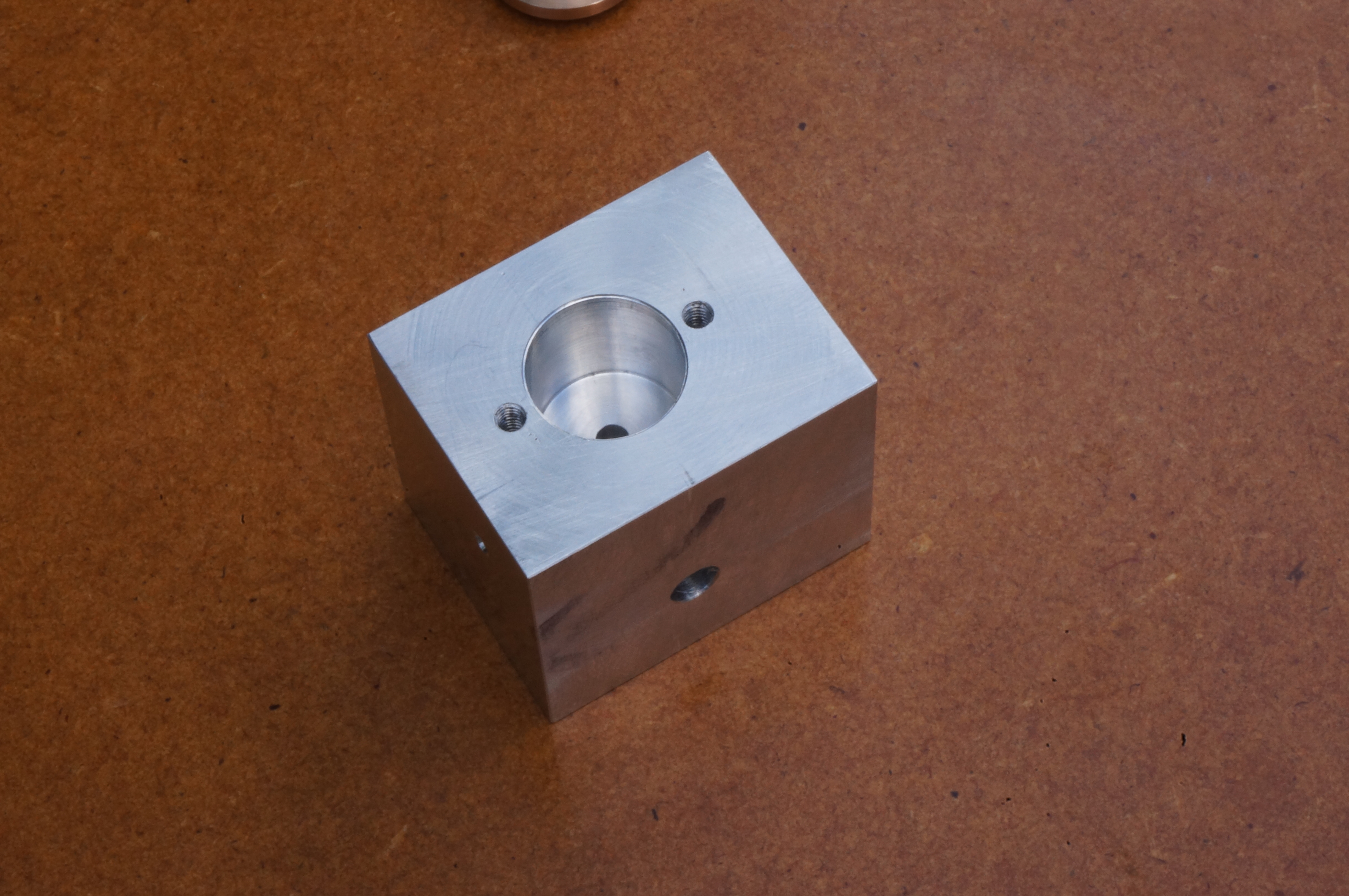
2019-08-24 - Shaping the body
Today I carried out all the exterior milling of the body, still using the lathe, as the mill saddle is in pieces while I work out how to correct a defect I suspect it may have had from new. This all went well, apart from a sharp looking ¾″ end mill that turned out to be not so sharp, and a misread dimension caused by not removing a burr, and resulting in the bolting flange being 0.018″ thin.
2019-08-28 - Drilling more holes
In a short session today, I completed the Carburettor body by drilling and tapping the 8-BA holes for the two bleed adjustment screws. (1 hour)


.
2019-09-04 - Modifying adjusting screws
Being an updraft carburettor, it is in a position that is less that ideal from the point of view of making adjustments. Finding the screw slots with a screwdriver and keeping it in the slot, on a running engine may be tricky. In had noticed the adjusting screw heads on a Stihl tool had a raised rim to help keep the screwdriver in place, and I decided this would be a good idea. I made two collars or sleeves to fit over the heads of the 8-BA cheese-head adjusting screws to try. (¾ hour)
2019-09-09 - Making more collars
In the light of the trial ones, I made another four mild steel collars today, to revised dimensions. They are 0.180″ OD, and 0.085″ long, with a 0.015″ wall. They are Loctited to the screw heads, and stand about 0.020″ proud of the face of the screw head.
The carb barrel needs two cut-away flats for engagement with the slow running and wide open stop screws. One of these has to be parallel to the choke hole, and the other at an angle. While tidying up, I did some thinking about how to set it up. (1 hour)
2019-09-14 - Milling barrel flats
A nicely ground 5⁄32″ pin, salvaged from a VCR, formed a good-enough sine bar, used with a rule for setting the angle for milling the idle stop face. The flats did not mill nicely, and the heavy burrs were difficult to clean up. I had to polish the OD before it would fit. I think the clamping force in the machine vice must have made the stem swell at the tip, as I had to polish that too, before it would pass through the cover flange. However, it will make for a good fit in the throttle lever.
The last job today was to modify two 8-BA screws for the throttle stops. (3½ hours)

2019-11-02 - Making a stud
A lot of time lately has been spent on rectifying and reassembling the milling machine, among other things. last job today, I started on cover flange studs (¾ hour)
2019-11-21 - Making another stud
Both studs completed and fitted. I could not find an 8-BA holder for threading the second end, so had to make a new one. (2¼ hours)
2019-11-24 - Making adjusting Screws
Today I made modified adjusting screws for the slow running air bleed and mixture air. It will not be possible to get a spanner to a locking nut on the latter, so I investigated a spring to put round the screw. Spring 4mm OD × 5mm long ordered. I decided to have a go at making a choke plate by hand, filing it to shape out of 1⁄32″ thick steel shim. I bent the handle tab a bit to close, but it will do for starters. (3½ hours)
2019-12-14 - Making a spring
The bought springs are just right for the rear bleed screw, so I finished the screw to length. It screws home just short of binding the spring. However, these springs are too big for holding the choke plate, so I made one to suit, having two turns of 26swg piano wire. I cut an 8-BA hex head to length and fitted the choke plate
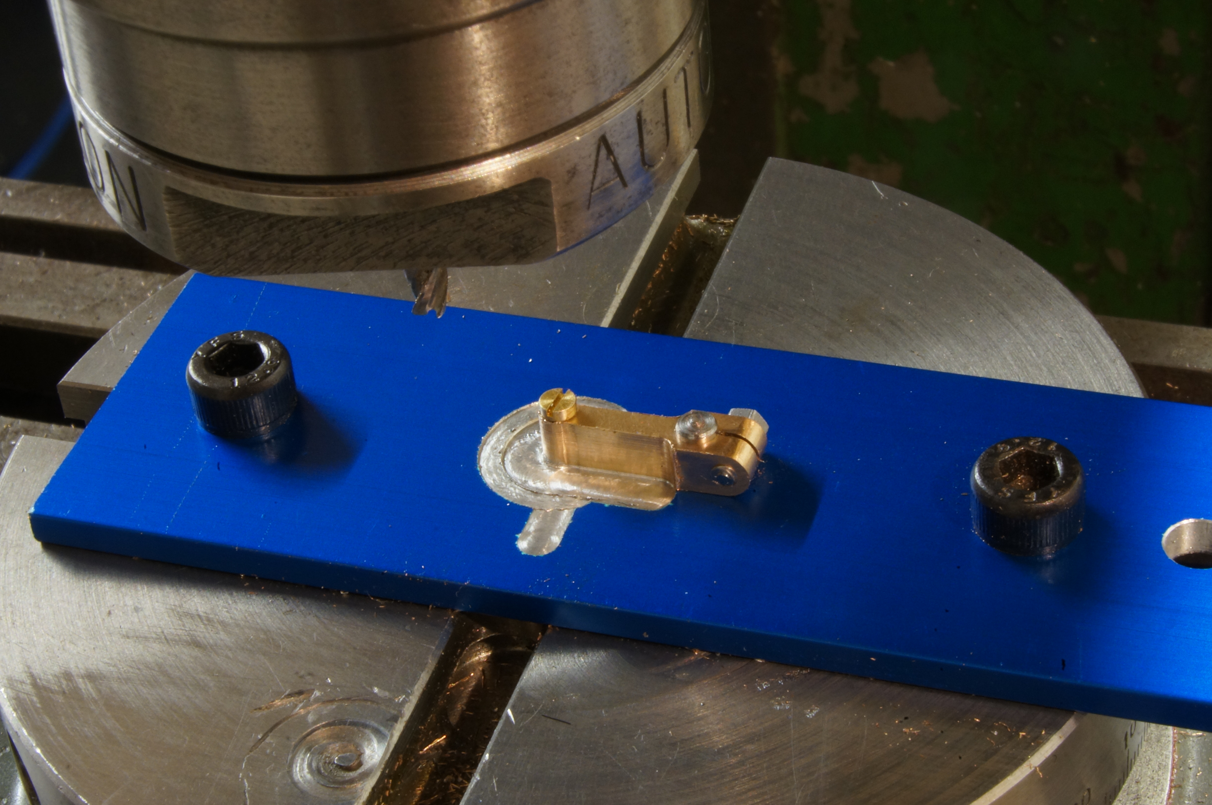
Starting work on my own redesigned version of the throttle lever, I parted off a slice of ¾″ diameter gunmetal and milled it (in the milling machine at last) to a rectangular bar, making it a shade over the final 5⁄32″ thickness. I milled one end square, providing a datum for drilling and tapping the 8-BA hole for the bolt that clamps it to the barrel spindle. (4½ hours)
2019-12-26 - Slitting the Throttle Lever

Today I milled the throttle lever to a smidgen over the nominal 3⁄16″ width, drilled and reamed the 1⁄8″ hole for the barrel spindle, and drilled a 1.7mm hole at the outer end, either for tapping to 8-BA, or to fit a 10-BA screw.
Using a newly made saw arbor, I slit the clamp end. I then made 5⁄32″ diameter filing buttons, one plain drilled and one tapped, and used them to file the radius round the clamping hole. (3¼ hours)
2019-12-28 - Making a milling jig
Today I made a jig for milling the throttle lever profiles. (2¾ hours)
2019-12-30 - Milling the flanks
Using the jig, I milled the sides and eye radius on the throttle lever. Initially it did not come out quite symmetrical. I could not work out why, but with a few thou available for finishing the flanks, I reset the jig and tried again, with a much better looking result. (2½ hours)
2020-01-19 - Turning the arm
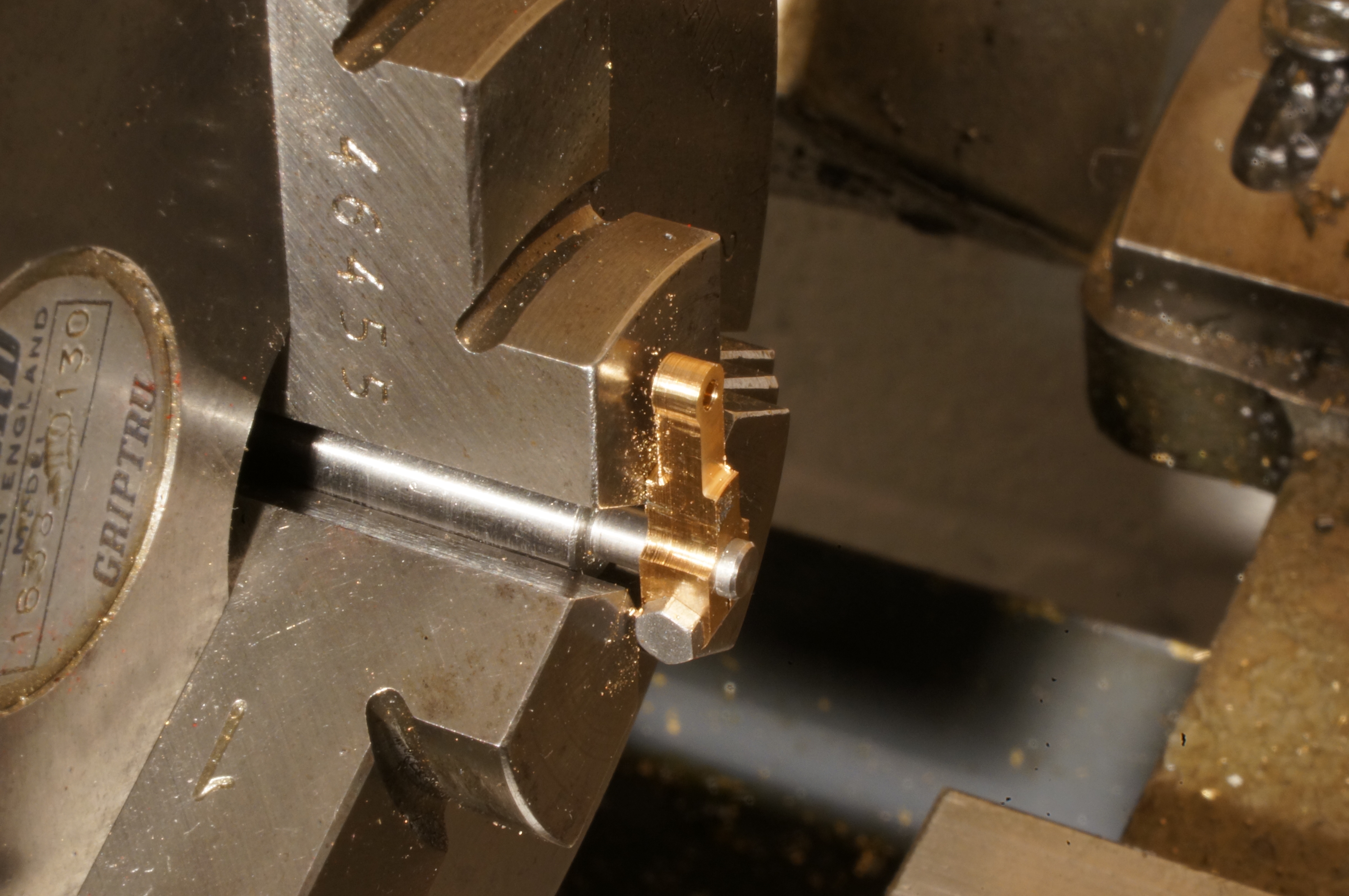
While setting up for the next milling operation, I decided I would turn away as much of the remaining material as possible without interfering with the split end. This meant I also needed to make a 1⁄32″ thick packing washer to support the eye during milling. (2¼ hours)
2020-01-25 - Milling radii
For milling the shoulder round the "big end" I also wanted a radius at the root of the arm. I honed a radius of about 1⁄64″ on the tips of a 4.5mm slot drill. First I milled the radius front and back to finish the lower part of the arm to thickness. Next, in a very tricky operation, I milled the shoulder arcs. (2 hours)
2020-01-26 - Turning the little end

In the last machining operation on the lever, I turned the front and back of the arm to match the milled thickness and leave small bosses at the eye end - this with the part held to a stub mandrel by a 10-BA (1.7mm) screw. I then spent some time removing machining marks, slight undercuts, rounding all the edges and polishing. Most of the work I did with slivers of 1200 grit paper wrapped round match sticks. I think that finishes the fiddliest little part I have ever made. (2 hours)
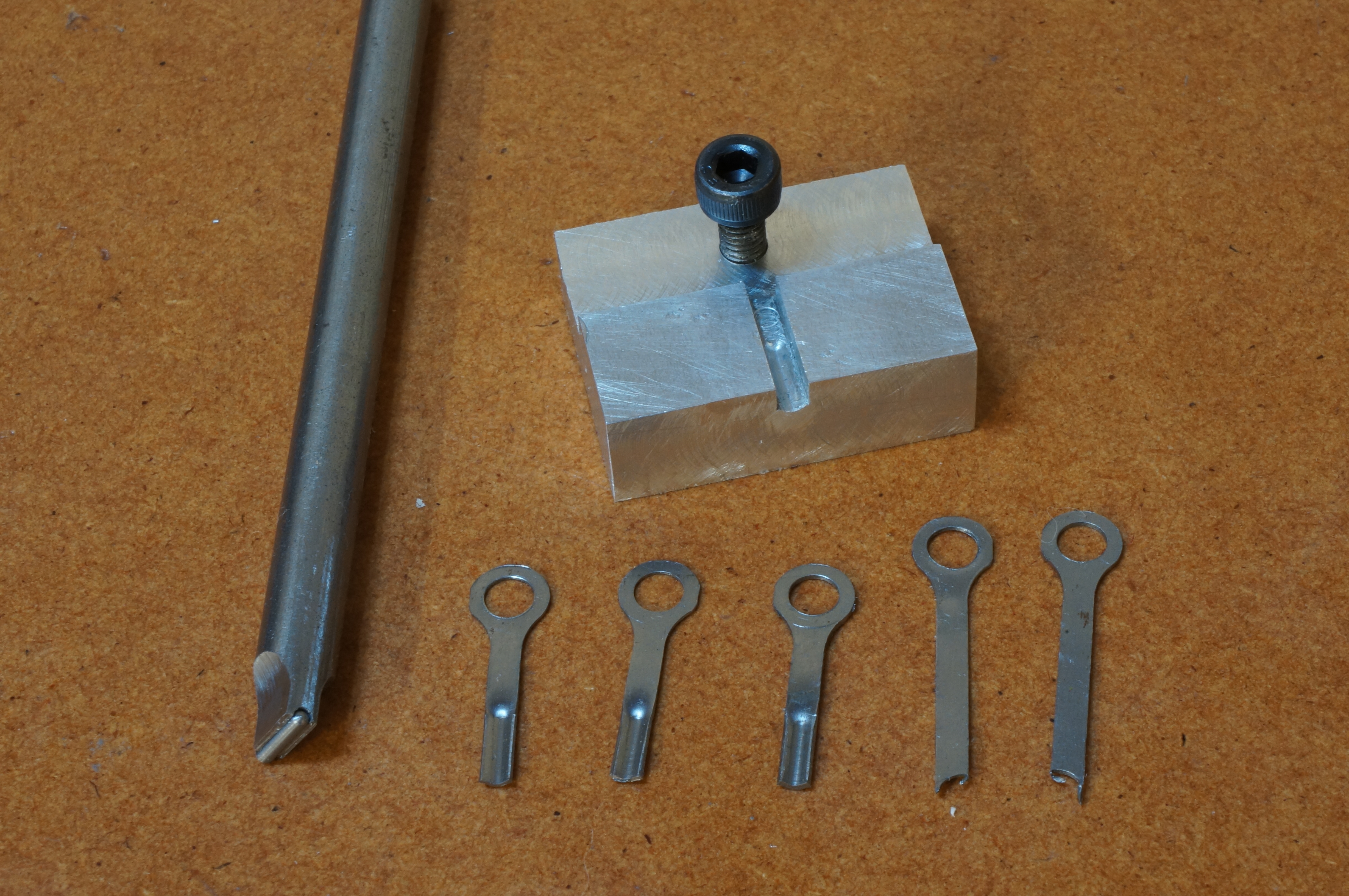
2020-02-01 - Making a trial spring clip
The last part for this assembly is a little spring, to be made up from flat strip, to hold the jet knob adjustment. I have recently acquired a small stock of CS70 annealed spring steel strip in various thicknesses. The original drawing calls for 1⁄32″ thick material, but that seemed to me too much. I decided to make rough trial clip in 0.020″ strip. Drilling and reaming produced reasonable holes, but I found it difficult to produce a decent looking shape by snipping and filing. It seemed to work OK, but was very sensitive to the amount of tension I set. I think the 0.012″ strip might be better. Anyway, part of the test was to see if I could harden and temper such I tiny piece. By heating it hanging on a thin wire held directly above the quench oil I was able to dunk it while still red. While cleaning it up for tempering, I dropped it. It remains missing. (2½ hours)
2020-05-23 - Making a temporary hose tail
While I intend eventually to have copper pipe between the tank and engine, I will use flexible tube initially. Today I made a hose tail and adaptor sleeve, Loctited the two pieces together and the fitted them to the carb. (1 hour)
2020-07-03 - Making more spring clips
Still having not much idea how to make the spring clip, or how thick it needs to be, I need to start with several blanks to make mistakes on. I cut three 0.012″ pieces, and two .020″ ones. I drilled 4mm holes at each end, spaced at 15⁄16″ centres. While thinking about a suitable jig for milling the profiles, I made up a centre locating pin for the small rotary table, tapped M4. I decided I would mill the blanks in one go, as a stack, sandwiched between jig plates. (2½ hours)
2020-07-04 - Making a jig
I cut up another of my supply of architects' sample anodised strips, and milled and drilled it to make a jig baseplate and clamping plate, and turned down the head of an M4 cap head to suit.
With the stack of blanks sandwiched in the jig, and the eye holes located on the rotary table by the centre locating pin, I milled the sides in 30 thou steps to ¼″ width and then thinned between the clamping bolts to a shade over 1⁄8″ wide. (3¾ hours)
2020-07-07 - Milling the blanks
I finished the flanks of the spring blanks, leaving them at 0.1″ wide, using a 3⁄8″ cutter to give a generous sweep between the eye and the blade. I then used the rotary table to mill the eye radius. The blanks are not perfect, but OK. (1¼ hours)
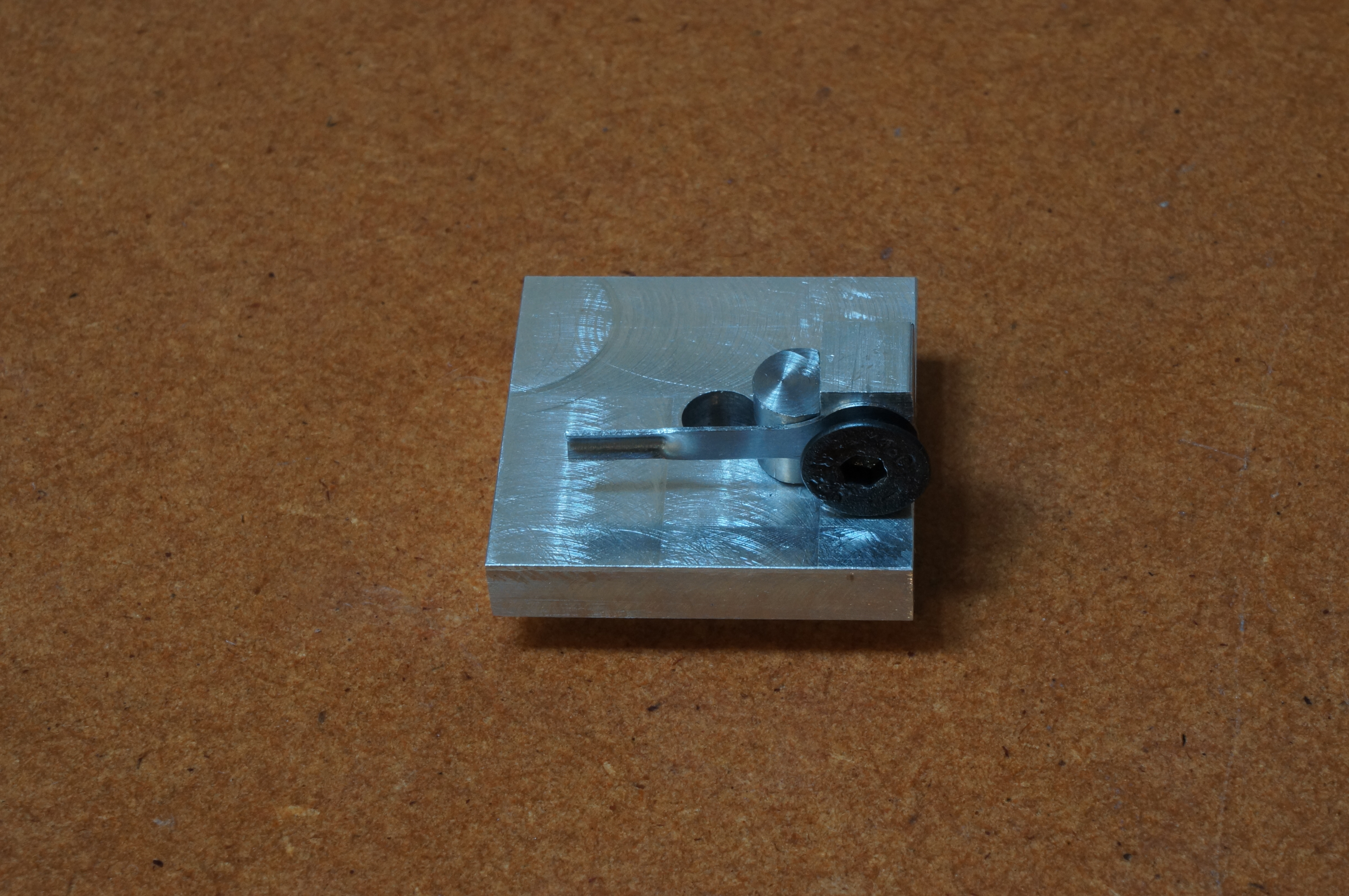
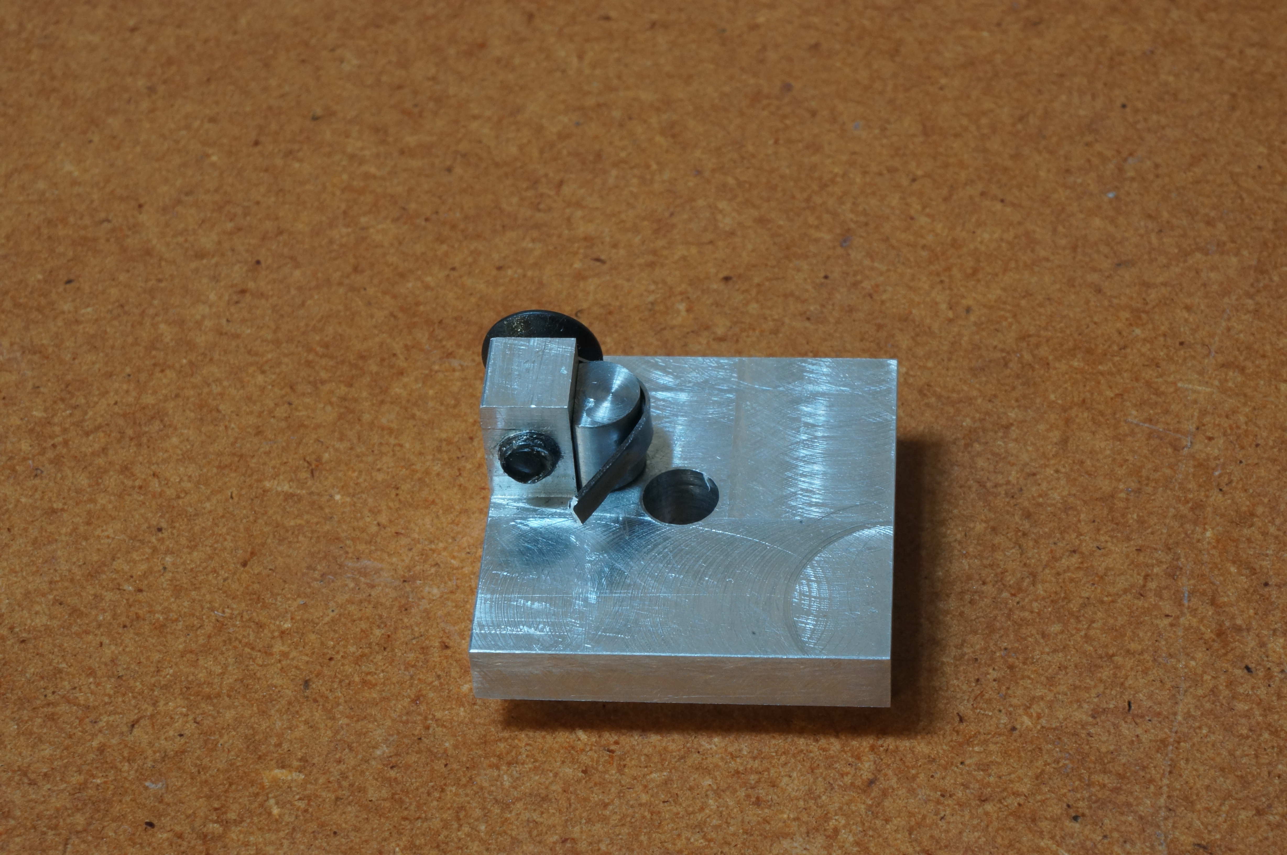
2020-07-12 - Making a swaging tool
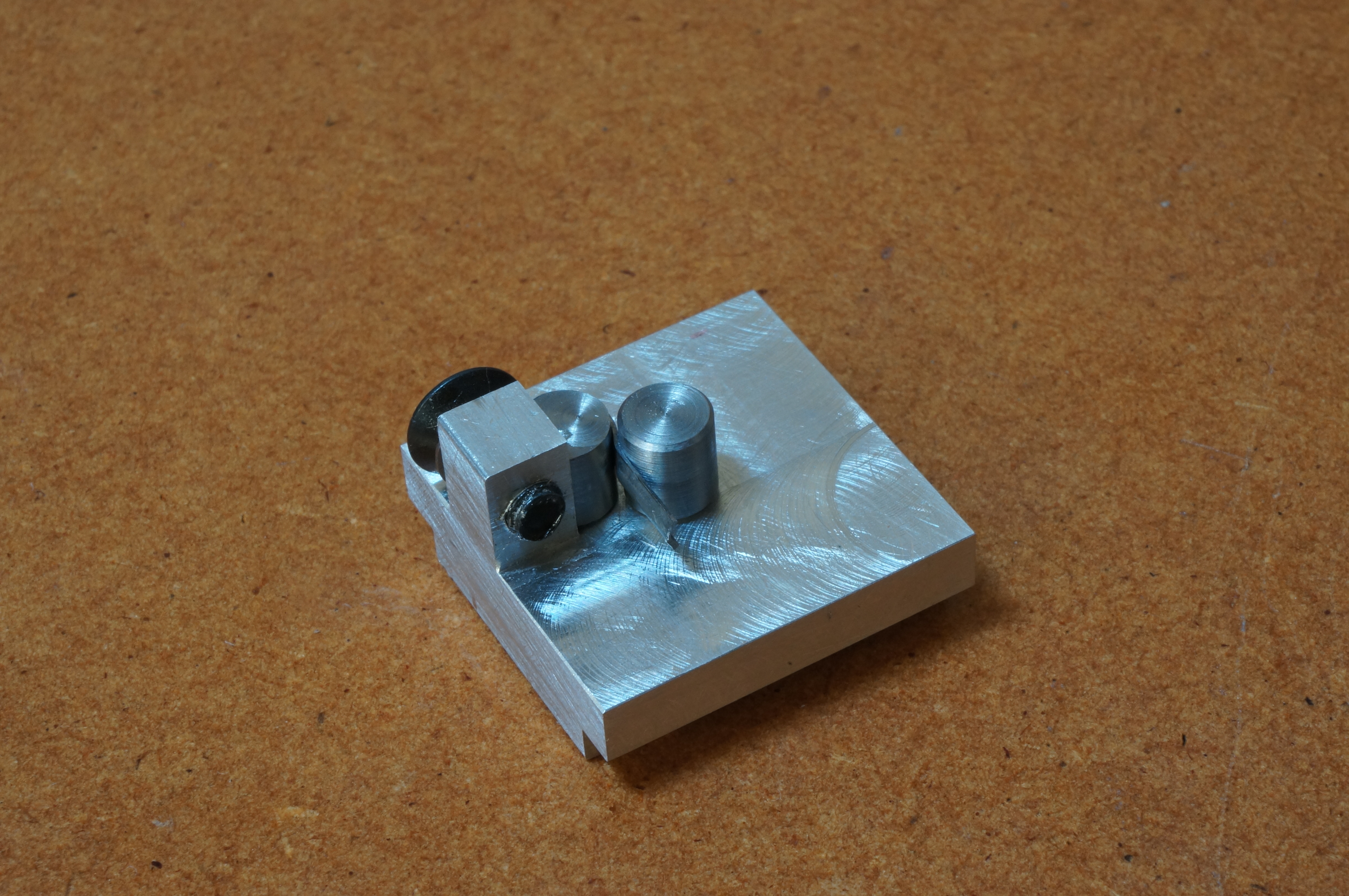
The next job on the springs is to cut them to length and swage the ridge that will engage with the scalloped edge of the mixture control knob. For this I need a die block and a guided punch. They will be used in the bench pillar tool. I milled a little alloy block with a step and a rebate across the raised part to take the blade of the blank. A tapped hole for locating the eye allows the blades to be finished to length, flush with the face of the block. Using a 1 mm radius ball-nose cutter, I made the female form groove 1⁄64″ deep. I made the punch from ¼″ mild steel by milling flats to fit in the slot in the die. I drilled a cross hole on line with the flats, then milled the end to leave half the hole.
After fiddly deburring, I tried the kit out on a 0.012″ blank, using the shank of a 1.4 mm drill as the forming tool. The result was exactly what I wanted, but I thought the tool might do a better job with a rounded end. I turned a suitable piece and filed a dome on one end. Trying one of the 0.020″ blanks, the result was a little more precisely formed. (5¾ hours)
2020-09-30 - Making a bending jig
I started work on another jig, this time for accurately forming the reverse bends in the spring clips. I did not get far before I realised my design was impossible to make. Back to the drawing office. Meanwhile I milled steps on the underside of the jig block so that it would sit nicely in the bench vice. (2 hours)
2020-10-03 - Bending springs
For the revised bending jig, I started by turning the two former pegs, leaving one on the bar for milling. I then finished milling the base to leave the little post standing above the surface, drilled the two vertical holes for the pegs, and drilled and tapped the hole in the side of the post for the clamping screw. Finally I milled a flat on the first peg, and parted it from the bar.
The jig turns out to be a bit tight, but I did manage to bend one piece. The countersunk head screw ensures the eye is correctly centred. It seems the swaged crease in the spring blank is slightly too long. (3 hours)
2020-10-06 - Hardening the springs
I swaged the last two springs leaving leaving a longer flat between the swage and the eye. After bending the two remaining thin springs, I reduced the diameter of the second form peg to accommodate the thick springs between the pegs. I bent the thick ones using a strip of metal to push them round the pegs, giving a tighter form than I could have done with unaided fingers.
I thought there might be a problem in hardening the springs in getting their tiny mass from the flame to the quench fast enough for them to still be red. In fact I had no problem with that. Cleaning them up and polishing ready to see the tempering colours was harder. While trying to polish a thin one with the Dremel I snapped it. At least it proves it was hard.
Suspending the spring on wire above a spirit flame, I tempered a thick one much too quickly. A thin one went better, but I may have let it down a bit too far. Tried in place on the carb, it fits, and nicely does the job of acting as a click spring for adjusting the jet knob. (3 hours)
2020-10-10 - Tempering the springs
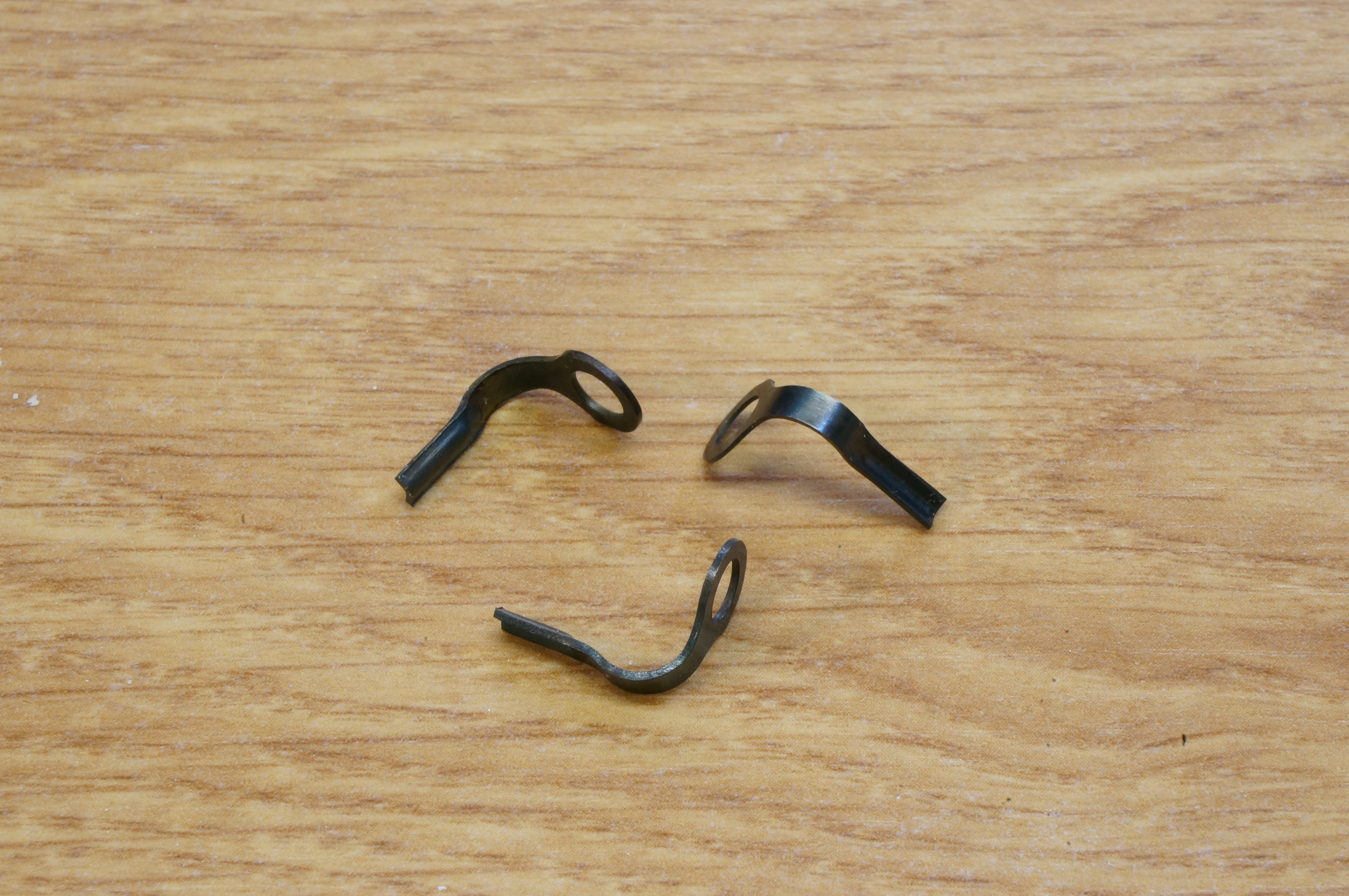
This morning I tempered the remaining three springs. So, that was the equivalent of three full working days to make these little buggers. But I like to think ETW himself would have been impressed with them.
Well now — that is the trial carburettor finished. And that (sort of) finishes the basic engine. Now there will be a whole lot of little things to be done before I can see if this thing will start. (3/4 hour)
.