
Ignition

I have bought the Tim 6 transistor ignition kit from Hemingway Kits, but have not done anything with it yet except peer at the little bits and scratch my head. (2022 Note: Hemingway is no longer supplying this item).
I have decided on twin-spark ignition and have bought a Minimag Novus 2 coil for the job. This system fires both plugs every revolution, giving a harmless 'wasted' spark, but avoiding the need for a distributor. It is only suitable for a 360° twin.
To trigger the ignition Hall-effect sensor, the two little button magnets need to be mounted in some kind of carrier. Rather than fix the carrier directly to the camshaft, I decided to make a ring, to be bolted to the camshaft gear, and to surround the camshaft gear retaining nut, thereby minimising the overall length of the assembly.
.
2013-06-22 – Making Plug Washers
Having put the plug holes in the Cylinder Heads, I found that the copper washers supplied with the plugs were too big to fit the 5⁄16″ diameter seatings. As a 'warm-up' job today I made some washers out of 5⁄16″ thick-walled copper pipe. Initially, parting them off left too much of a burr to deal with easily on such a small part, so I made a steel mandrel to fit inside the tube and parted some more with this in place. I found they needed a shave turning off the outside as well. After rubbing the faces and cleaning up the bores, I annealed them by putting them all between two small steel plates and heating the whole lot up to red.
2014-01-04 – Starting the Timing Ring
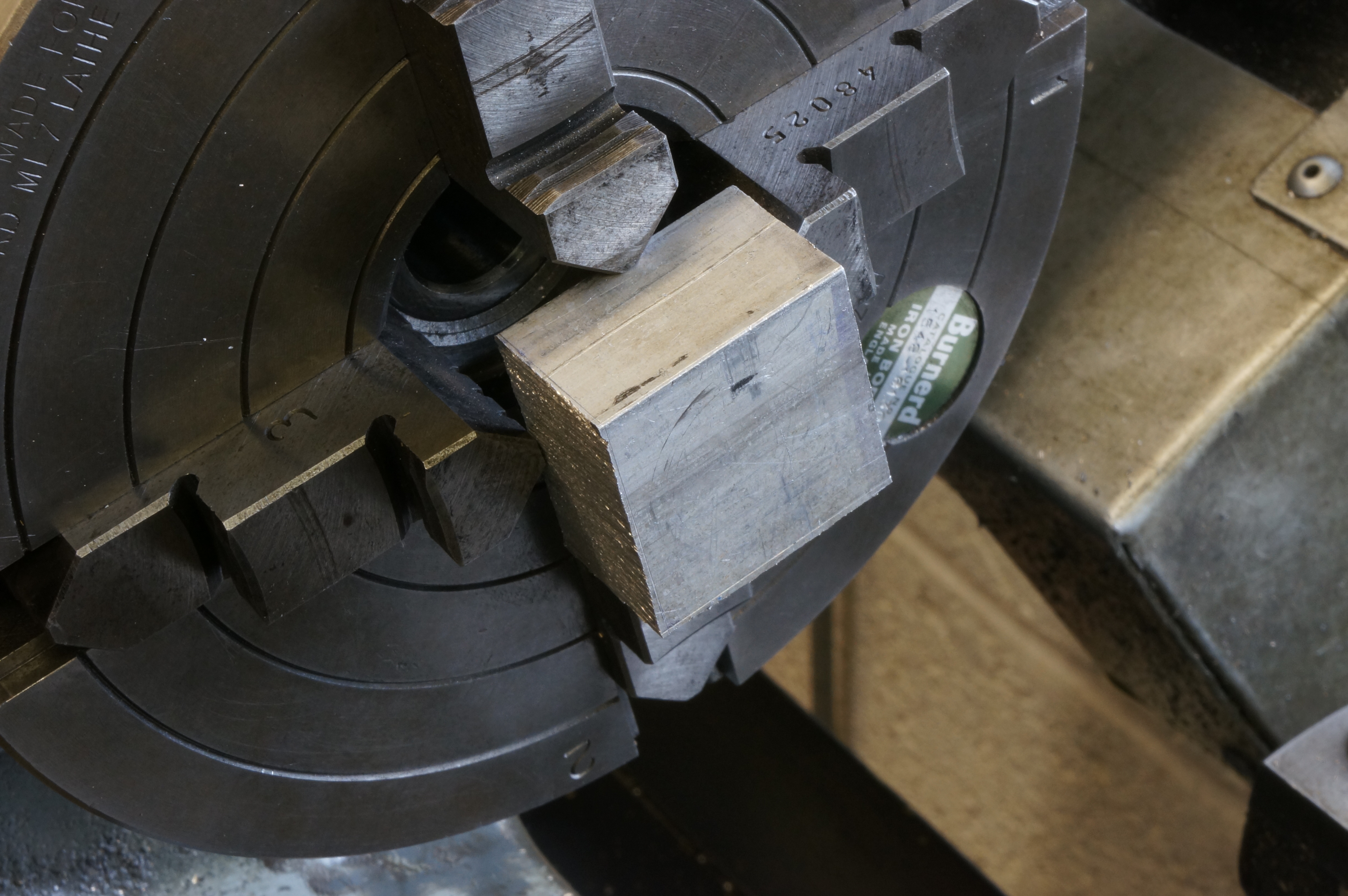
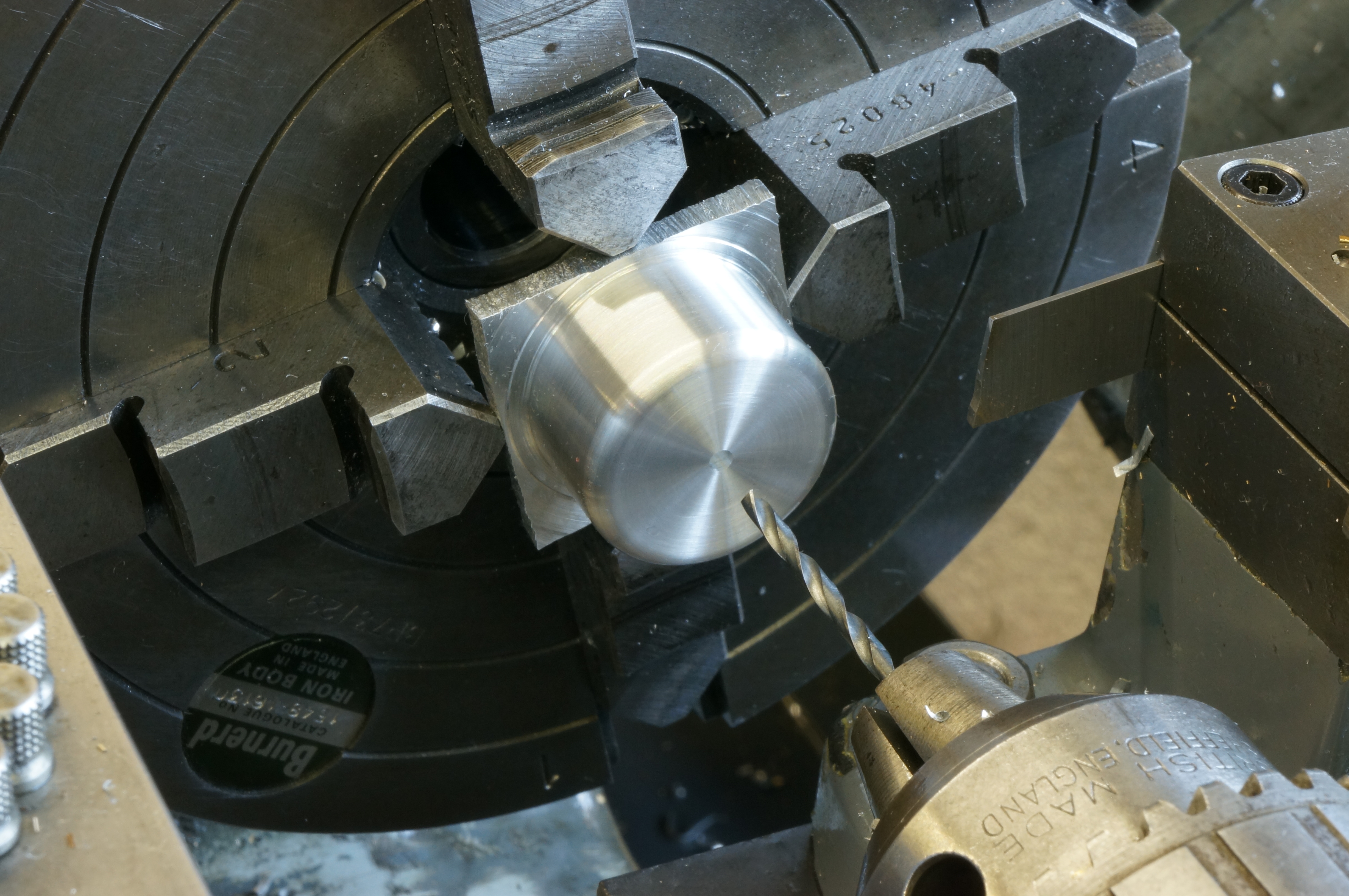
I sawed out a square piece aluminium alloy, large enough for the ring and a chucking piece, and turned the face and diameter of the ring. (1 hour)
2014-01-04 – Completing the Timing Ring
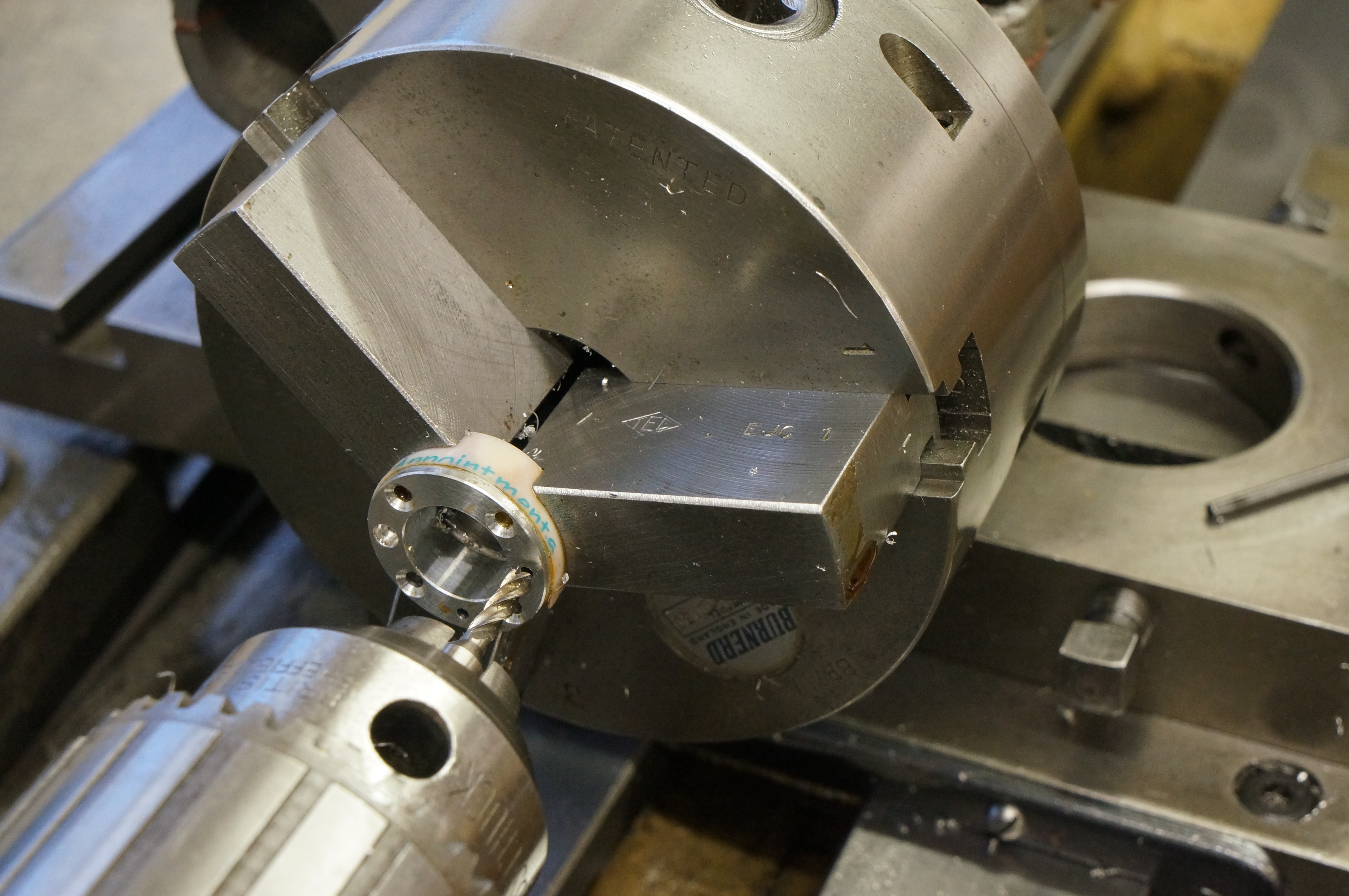
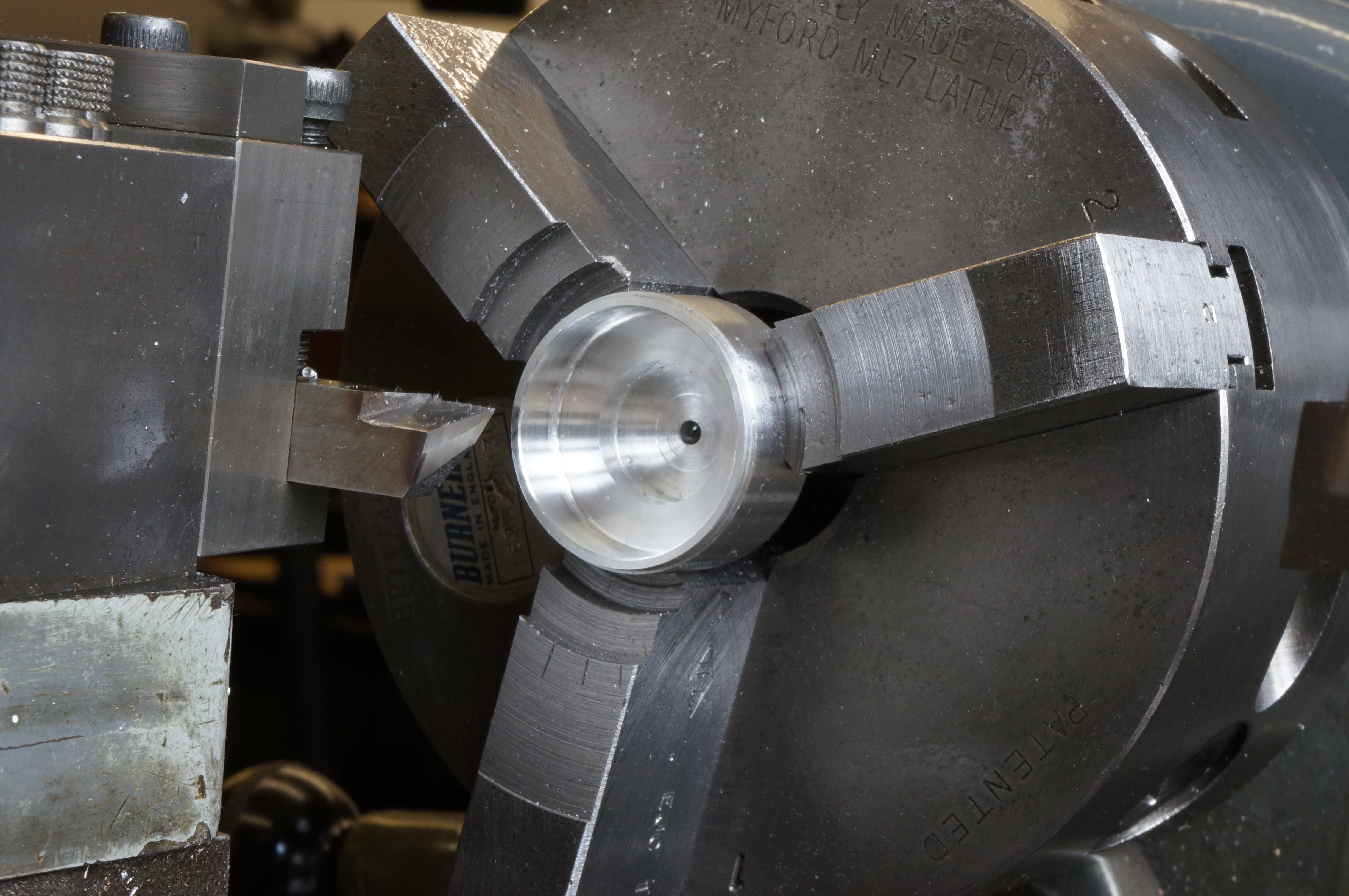
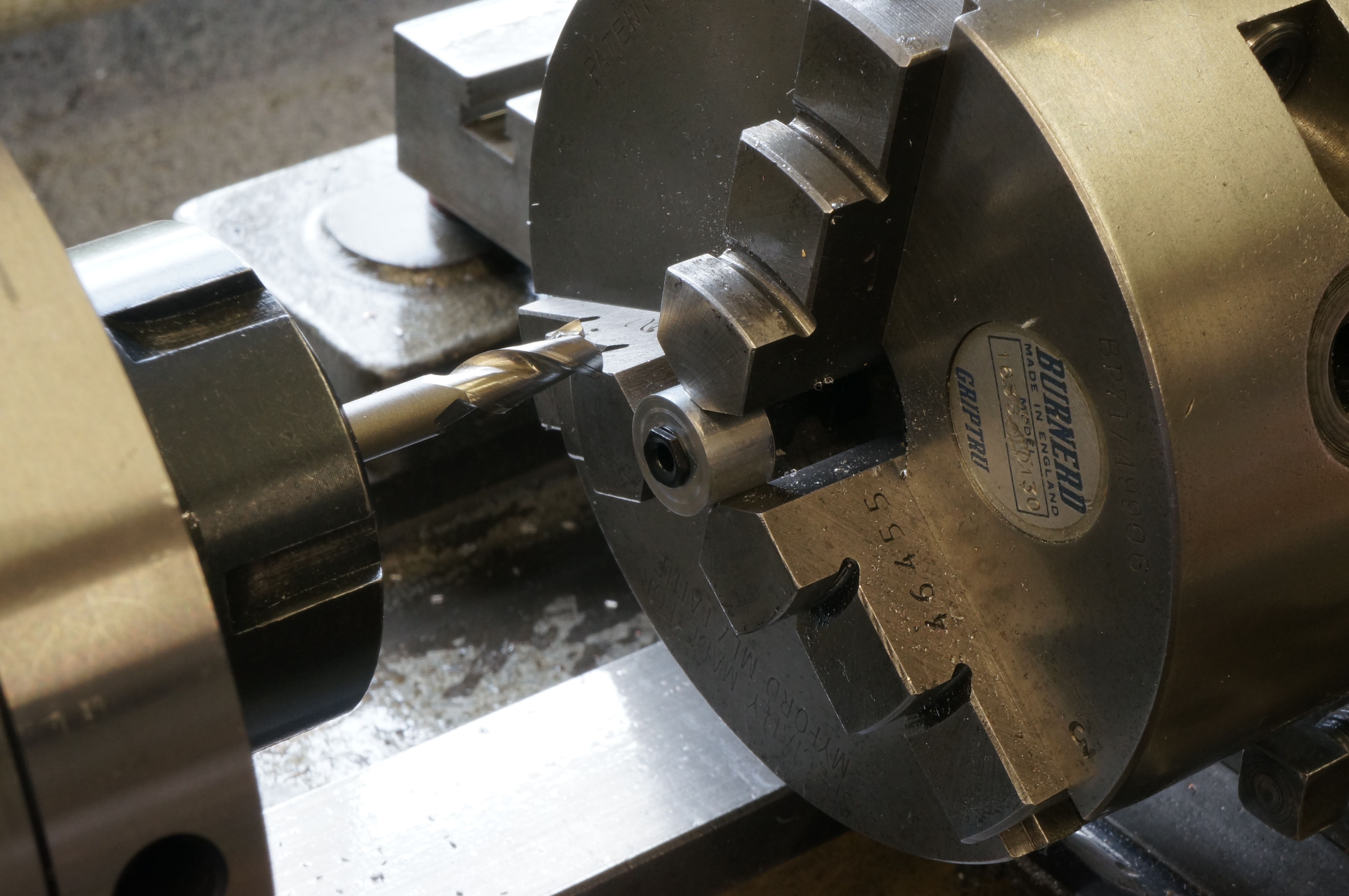
First, I bored the ring to fit on its shoulder on the timing gear (0.5315″), chamfered the edges and parted off. Next, I set it up in the 3-jaw chuck with soft jaws and card protection, and adjusted the Griptru chuck to ½ thou, faced it to length and again chamfered the edges.
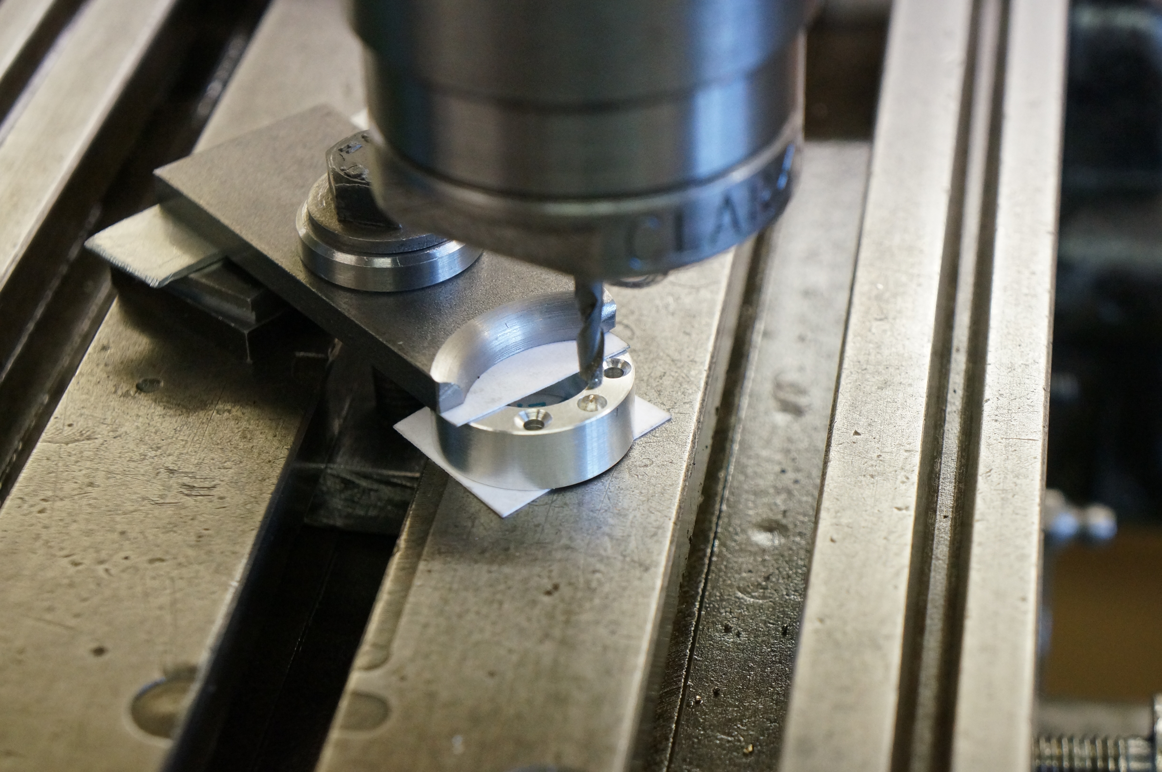
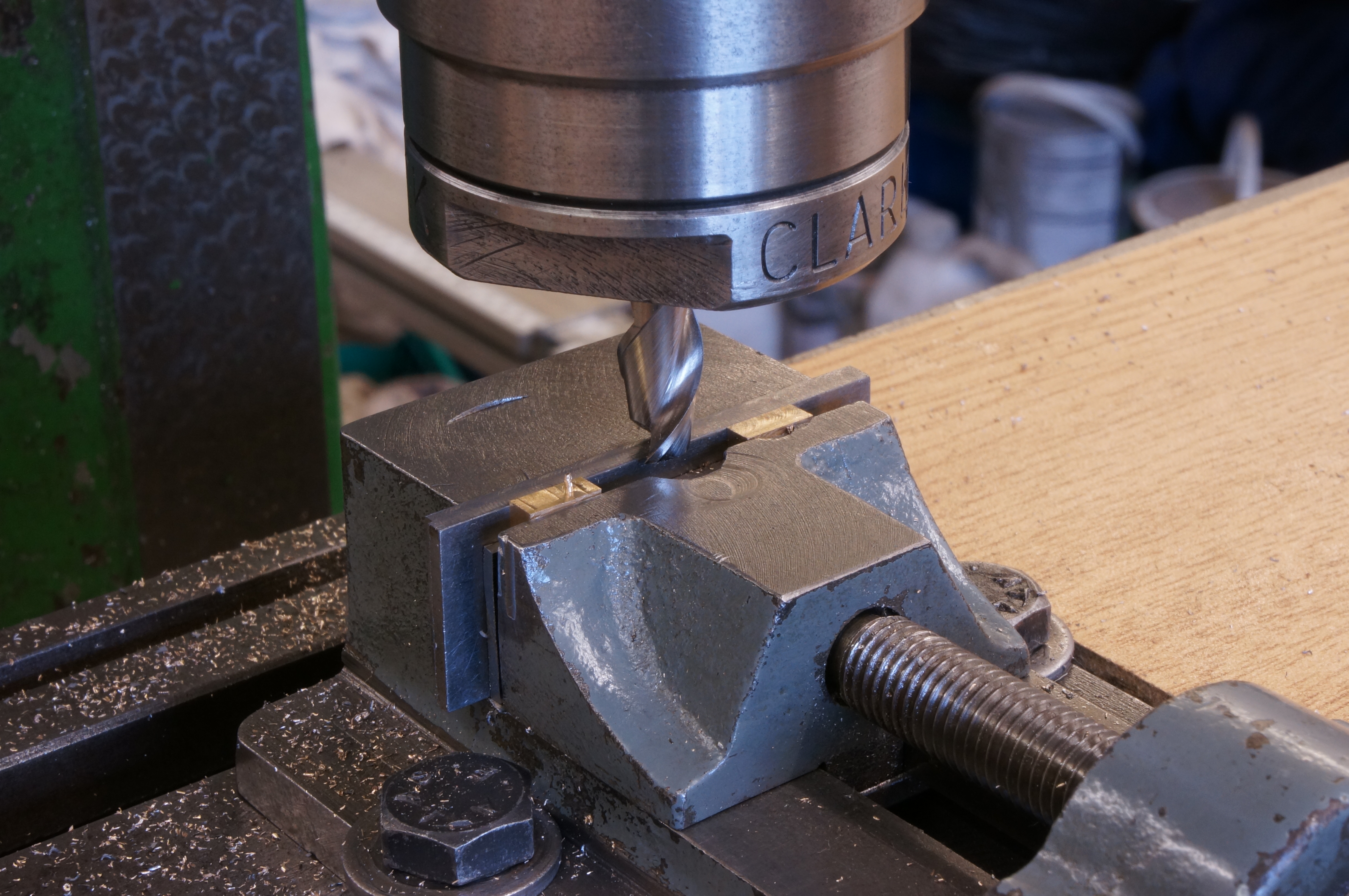
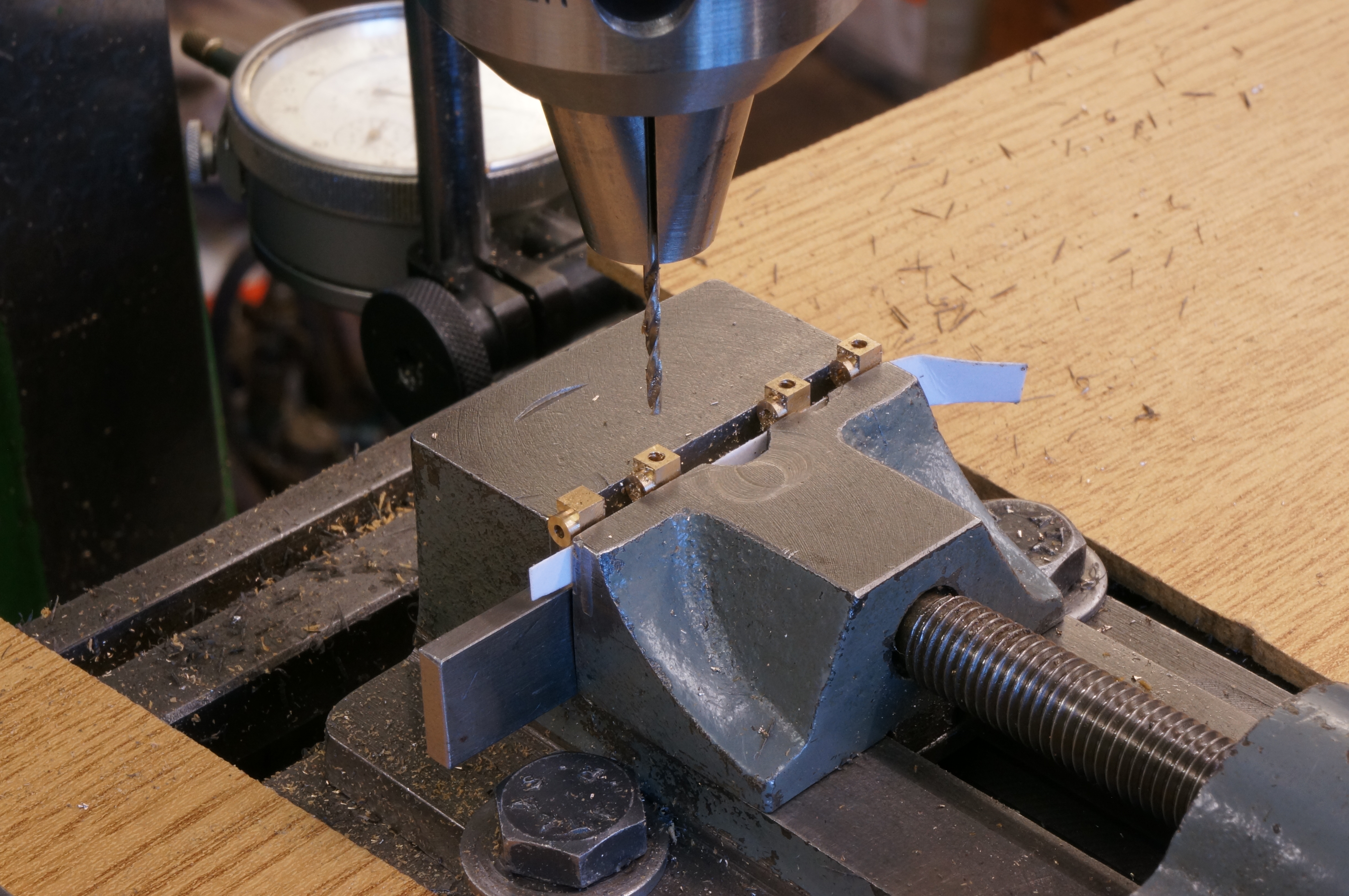
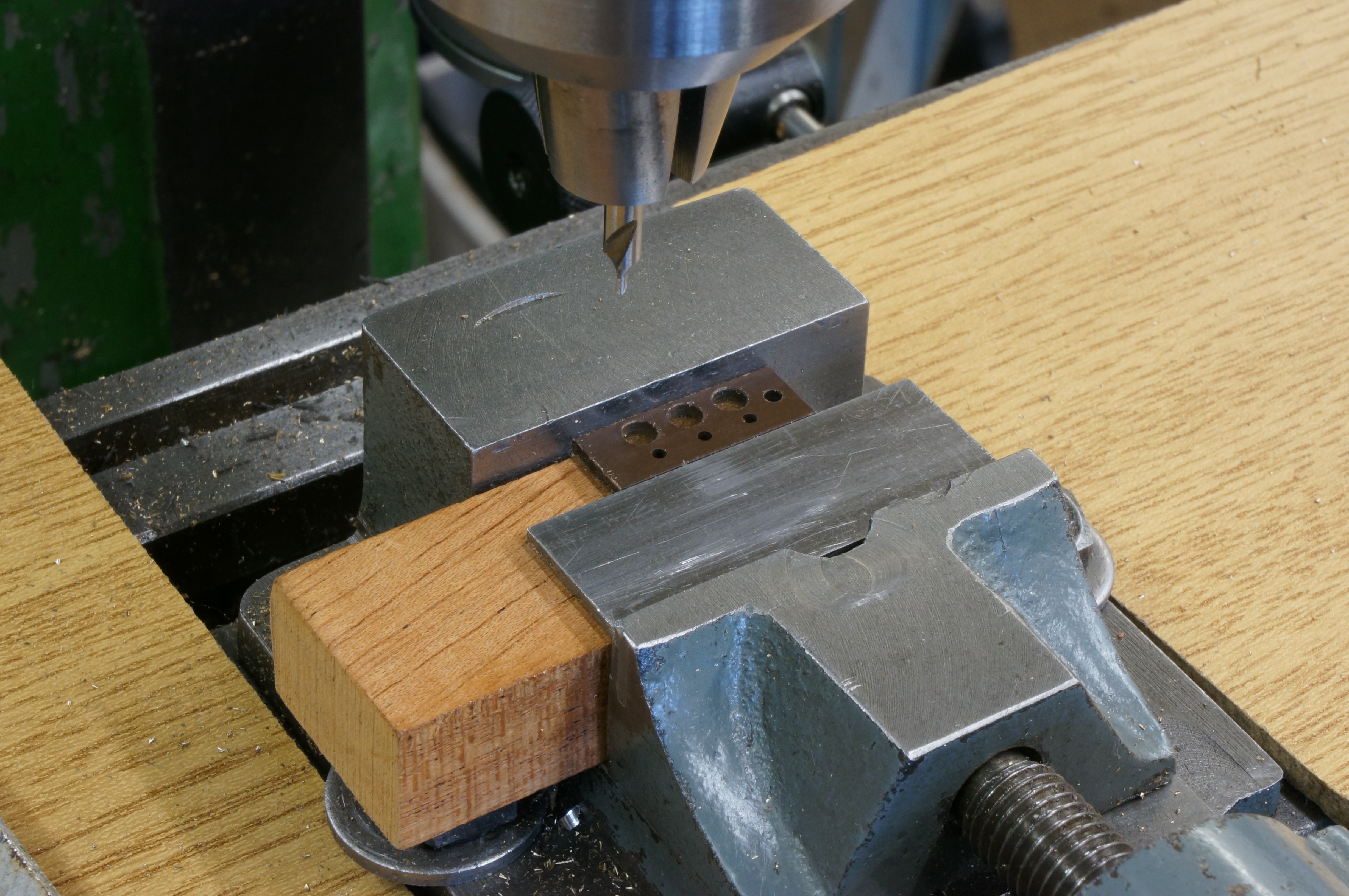
In transferring the chuck and job to the dividing head on the boring table, I re-checked the truth, and as the DTI was reading nearly 2 thou out I decided to reset, but could not get better than ½ thou. In clocking the ring on the spindle centreline I found it was about 0.006″ low, but this will make no material difference to drilling the holes. The holes cannot go right through without drill into the chuck jaws, but they can be drilled part way and finished in the drilling machine. I carefully countersunk the four 2.3mm holes for the 8BA mounting screws almost to the edge of the ring, as it is important that the screws heads fit flush. I drilled the two pockets for the magnets 1⁄16″ through, to allow a pin to be put in from the back to eject the magnet if it ever becomes necessary. The pockets proper were cut 1⁄8″ diameter by 1⁄16″ deep with an end mill. There is also one 1⁄16″ hole for a dowel pin to ensure the correct timing. The holes were finished all the way through in the drill press.
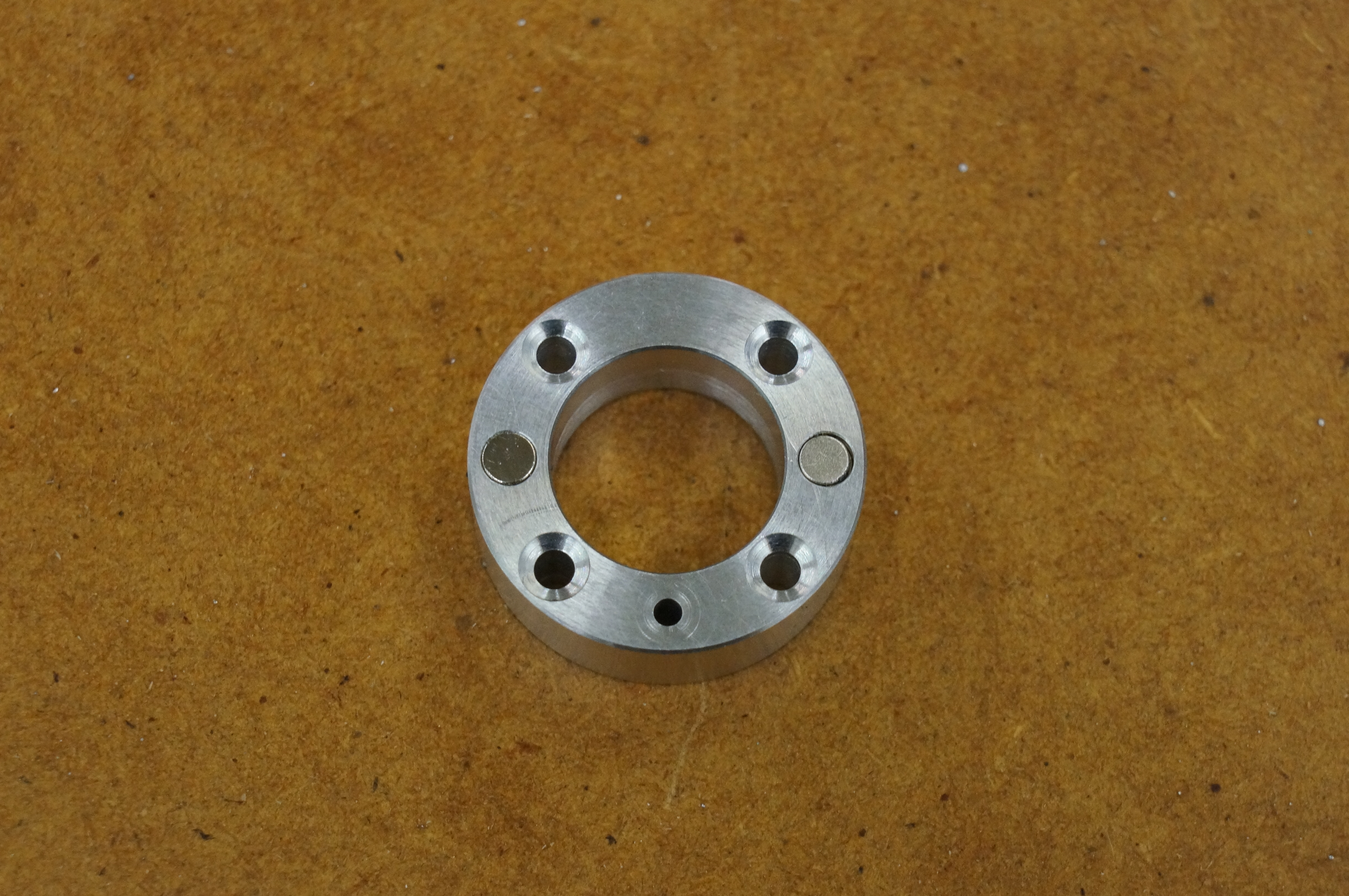
The fit on the gear is a bit tight but it will be OK. The bought countersunk screws do not fit flush and will need doctoring so they do. I cleaned the job up, and fixed the first magnet (from the Howell kit) in place with Loctite bearing retainer (641). The extra magnet turned out to be only 1mm thick instead of 1⁄16″ so I made a brass washer to fit the pocket, 0.022″ thick and glued it in place, followed by the magnet. Idiotically, I had failed to check the diameter of the second magnet. It was a very sloppy fit. It must be 3mm diameter. I don't think I could be sure it would stay in place, so something will have to be done. (2¾ hours)
.
2014-03-01 – Reworking the Timing Ring
I emailed Kirk at Hemingway to explain there was a problem. He thanked me for making him aware of it, and sent a new 1⁄8″ by 1⁄16″ magnet. Using a little piece of 1⁄16″ silver steel as a drift, I knocked the undersize magnet out of its pocket. The spacer was more firmly fixed and would have to be machined away. Initially setting up on the hole, I could not make sense of the dial readings, but eventually concluded there was a residue of Loctite in the hole. Once I had cleaned it out it was much easier. Clocking up a 1⁄8″ hole is one of those jobs where it is worth fitting the smallest diameter ball probe on the DTI. Once set up, it was easy to machine away the spacer with a slot drill. Finally, I cleaned the parts with Loctite cleaner and glued the new magnet in place, having double-checked its orientation with a compass. (1½ hours)
2017-03-29 – Starting the Hall Sensor Terminal Block

Being short of a small piece of rectangular section brass, I re-purposed the earth pin of an old 13A plug to produce 1⁄8″ thick bar to make the terminals. I put the bar in the 4-jaw and turned a boss, drilled it, and parted off the first terminal. I also cut out the pieces of material for the terminal block and cover. This thing is going to be small. (1½ hours)
2017-04-18 – Turning Terminals
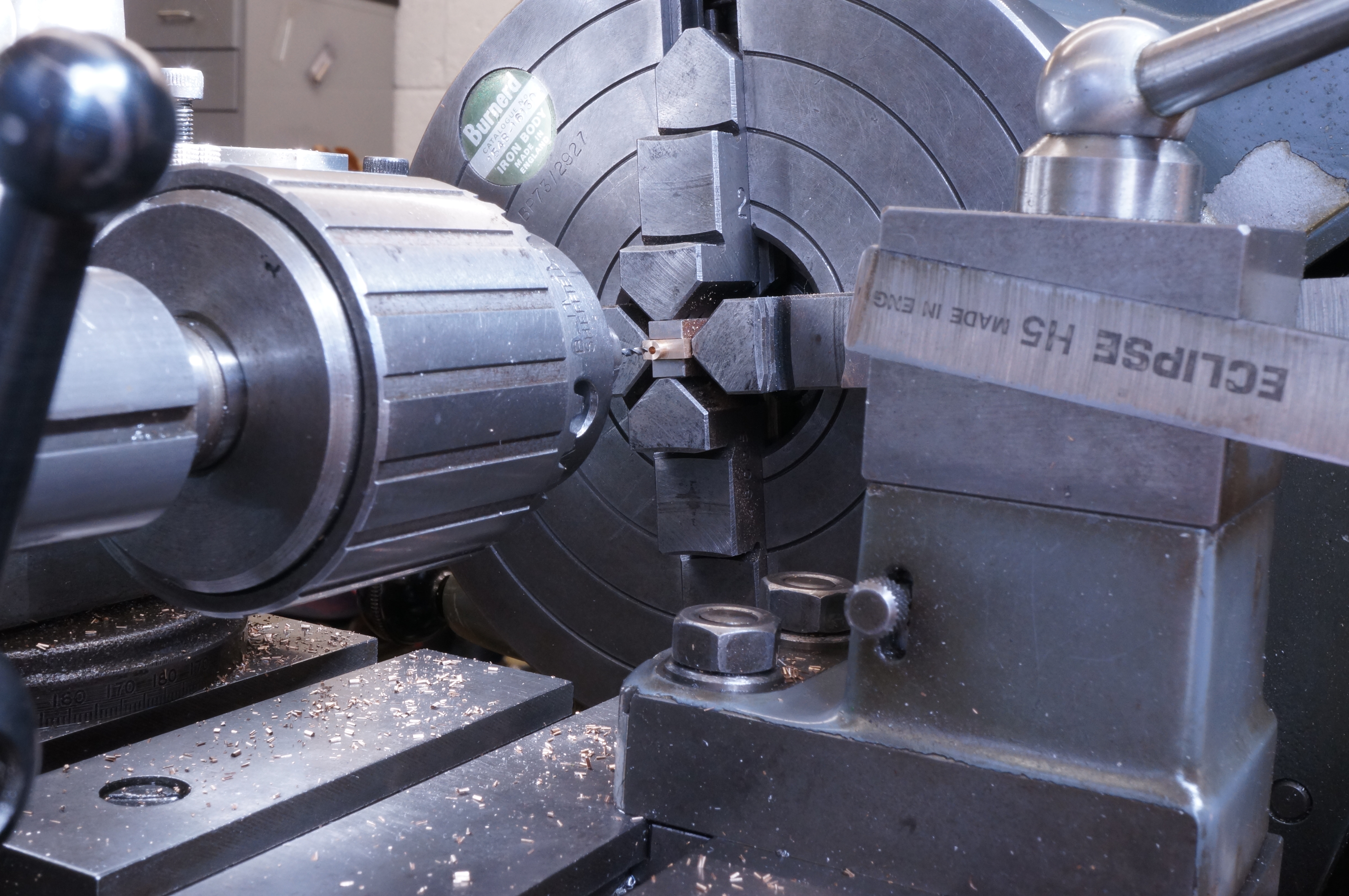
In a short session today I first op turned and parted off two more terminals and a spare. (¾ hour)
2017-04-22 – Milling Terminals
I made a support plate with notches to take the projecting bosses on the tops of the terminals so that the bottom faces, where they were parted off, could be milled to size. Next, I drilled the terminals for the wire entry. I tapped one of the 10-BA terminal screw holes to see how they went, not having needed to use so small a tap for quite some time. It went nicely. I also milled the delrin terminal block and its phenolic cover plate to their external dimensions, and finally sawed out a chunk of aluminium for the timing cover. (5 hours)
2017-04-23 – Starting the Timing Cover
In a short, late afternoon session, I gripped the timing cover block precariously at the tip of the 4-jaw chuck. I turned and faced it, then cut three chamfers for the edge radius, blended them in with a file, and sanded to a finish before finally drilling the central hole to complete the first op. (1 hour)
2017-04-29 – Boring the Timing Cover
Having first bored the soft jaws to fit, I faced the timing cover to length, having to take it out of the chuck for measurements. I then roughed the central deep recess and finish bored the outer recess and its internal chamfer. I ground a tool to a sharp point and cut the external seating shoulder to a half thou clearance it the timing case. This turned out a good fit with no shake, but it could have been a little tighter.
After spending some time thinking about a compression gauge and looking out what I might have around to make one, I made the tiny pressure pad to fit in the central hole of the timing cover, and finished the day by drilling the remaining 1mm and 1.3mm holes in the terminals. (5 hours)
2017-05-01 – Drilling the Terminal Cover
Today I sharpened some drills and drilled the terminal cover. (1 hour)
2017-05-07 – Milling the Terminal Block
Today I started by drilling the mounting holes in the terminal block and fitting it to a machining block, so the terminal slots could be drilled. After deburring I found it was tight on the terminals, and eased them, especially on the bottom corners. I also opened the holes in the cover plate enough to allow the terminal block to be assembled. I then tapped the remaining holes in the terminals.
Next I dealt with the timing ring screws. I cut the countersinks in the ring a little deeper. Then I selected four of the 8-BA countersunk brass screws with the thinnest heads, and removed the burrs thrown up by cutting the screwdriver slots. With this done, I fitted the ring, with its dowel in place but not Loctited. The screw heads are now flush, and I measured the projection of the ring face to check the clearance for the Hall sensor.
I trial wired the terminal block and tried a Hall sensor leg in place to check the lengths of the 10-BA terminal screws. The wiring screws need to be 5⁄32″ long, and the sensor leg ones 1⁄8″. I finished the shorter screws to length by screwing them through a plate and filing flush on the other side.
I also spent a while thinking about the job of soldering up the TIM-6 ignition circuit. I bent the power transistor legs to fit the board. (5¼ hours)
2017-05-13 – Making a Cable Gland
Today I started by making the outer part of a cable entry gland for the Hall sensor wires. The first step was an internally threaded chucking piece to be used for the second operation turning. Next, I turned the delrin gland and screwcut it it to fit the chucking piece, then parted off. I made a D-bit tool to cut a cable entry radius. This did not work well, and after facing to length, I ended up making the radius by hand, and for some reason I could not even get a polish on it, and decided to move on. I milled the external hexagon using the dividing head on the lathe cross slide.
I also shortened the three remaining terminal screws to 5⁄32″ length, and made a start on another pin from the 13A plug to make a mounting plate for the Hall sensor. I drilled the holes off centre, making a scrapper of that one. Tidy up. (5 hours)
2017-05-27 – Making a holding block for the Timing Cover
Another attempt at the Hall sensor mounting plate ended in milling it too thin. Do something else while this job sits in the mental slow cooker. I need something to hold the circular timing cover while I mill out the rectangular recess for the terminal block. I found a suitable aluminium clamping block from a previous job, and bored it out for the cover. It fitted well enough to put a scratch on the finished cover surface. (2 hours)
2017-06-23 – Finishing the Timing Cover
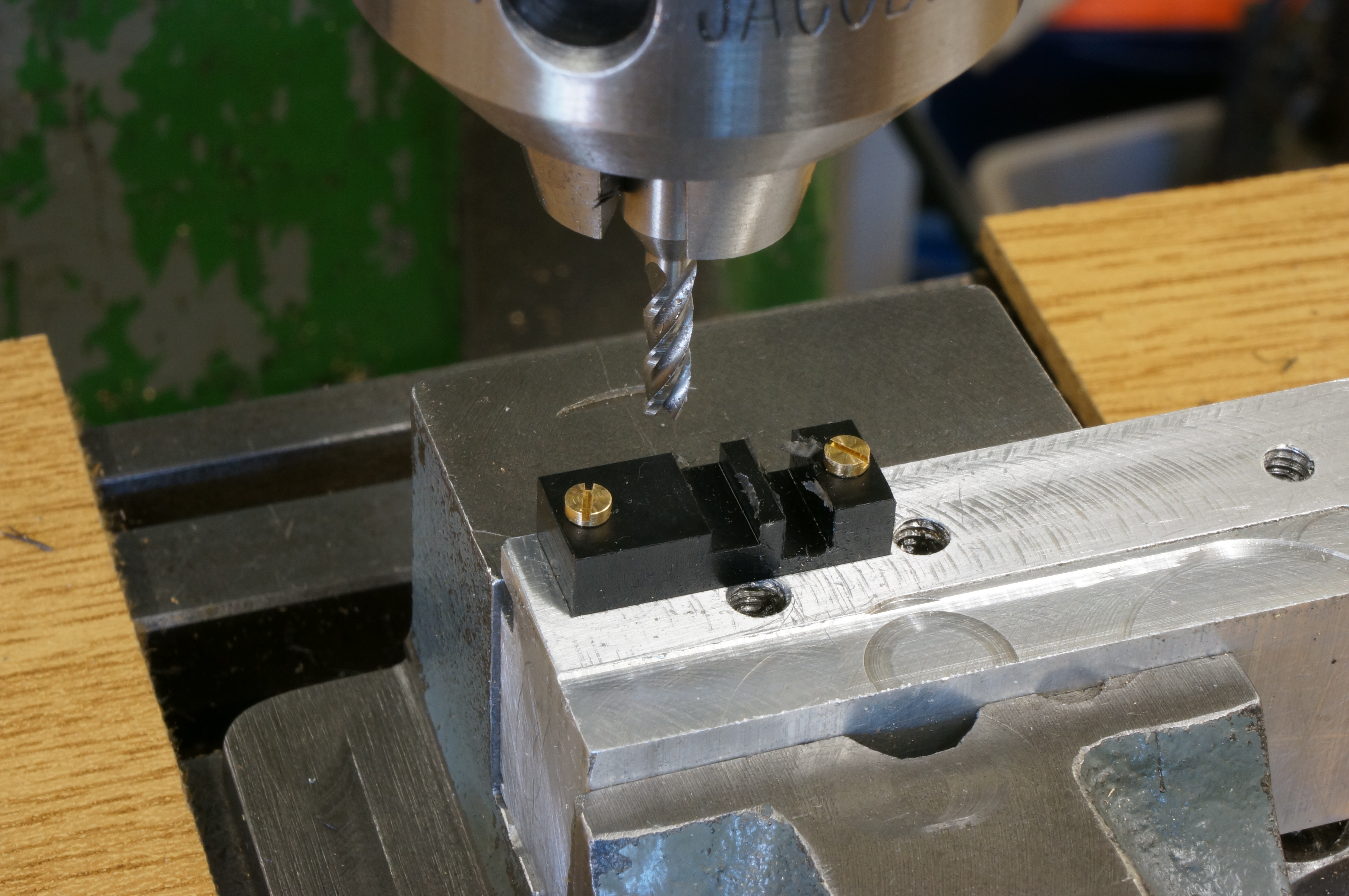
I set up the timing cover in the clamping block in the milling vice and machined the terminal chamber, then drilled and tapped four 10-BA holes, two for the terminal block, and two for the Hall sensor mounting plate. Next I drilled the two diametrically opposite radial holes, one for the cable entry gland, and one for the advance control arm. Having forgotten to spot-face it, I had to set up the gland hole a second time. The terminal block fits nicely. (4 hours)
2017-07-29 – Making Sensor Mounts
After another failure, I eventually milled a Hall sensor mounting plate. (3 hours)
2017-08-03 – Finishing a Sensor Mount
I made a couple of filing buttons, 1⁄8″ diameter x 10-BA. These were mild steel and not hardened. I use them to file the ends of the sensor mounting plate. The mount also needed a slight relief filing to clear an internal corner radius in the timing cover. It now fits nicely. (1 hour)
2017-08-05 – Mounting the Sensor
The first job today was to fix the Hall sensor to the mounting plate with Araldite. Next, I cut screws to length for the sensor and terminal block. The latter screws fit in through holes in the face of the timing cover, so I domed and polished the visible tips of these screws. I also made the Retaining Clip that holds the timing cover in place. I used a piece of shim steel, drilling the hole first before filing to shape, using buttons to round the fatter end. (2½ hours)
2017-08-06 – Assembling the Timing
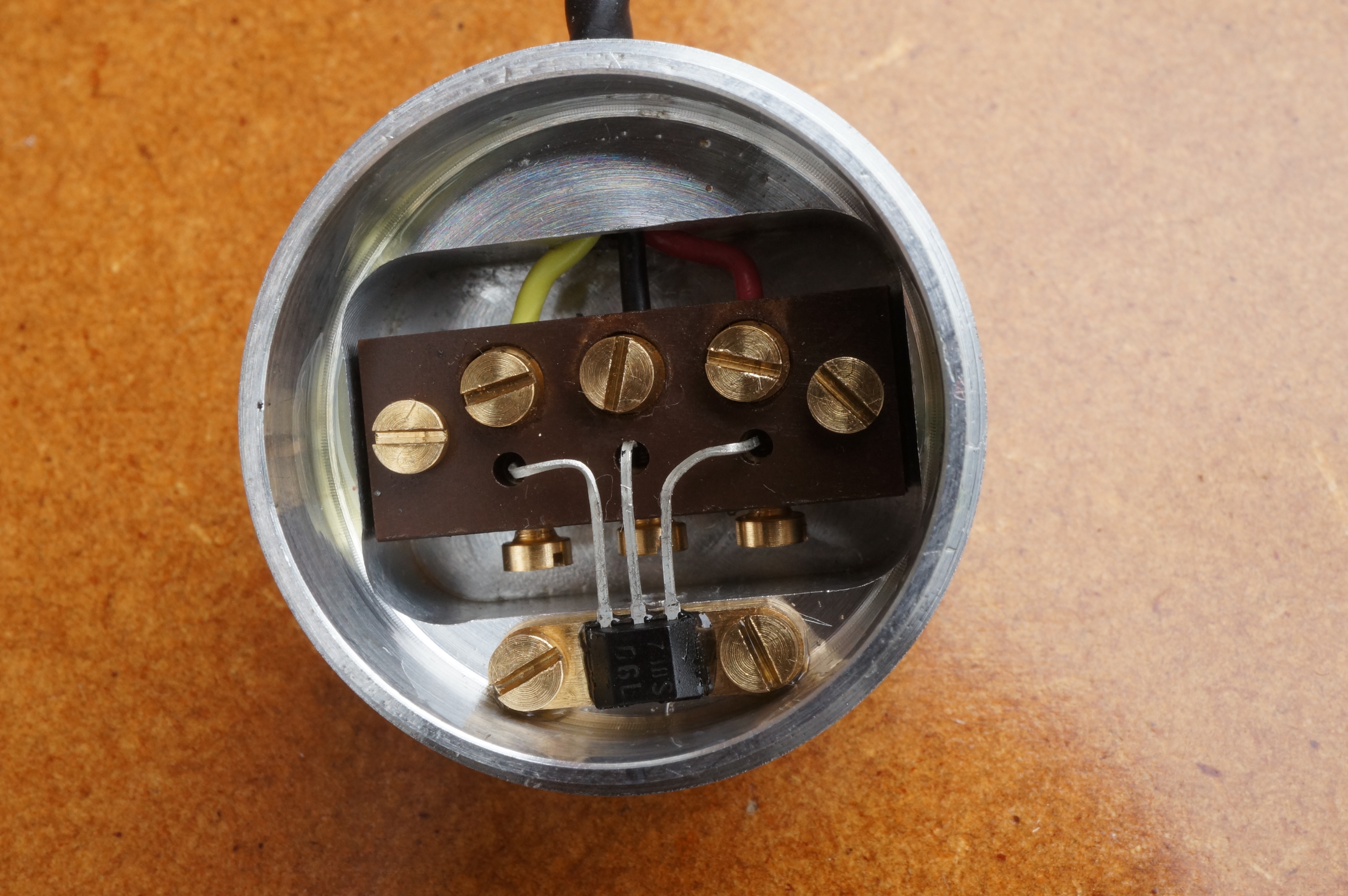
Having checked the the Hall sensor is properly glued, I bent and cropped its legs to fit the terminal block, and assembled the timing cover. (¼ hour)
.
2017-08-10 – Making the Retaining Clip Post
This post or pillar replaces one of the nuts holding the Timing Case to provide a fixing point for the Retaining Clip. After first op. turning, I milled the hexagon, the returned to face to length, drill, and tap. On trial assembly I found the clip is slightly short, but it will be OK, at least for now. As expected, the clip needed a slight bend to get the right amount of force on the Timing Cover. (2¾ hours)
2017-08-11 – Making up and testing the Ignition Circuit Board
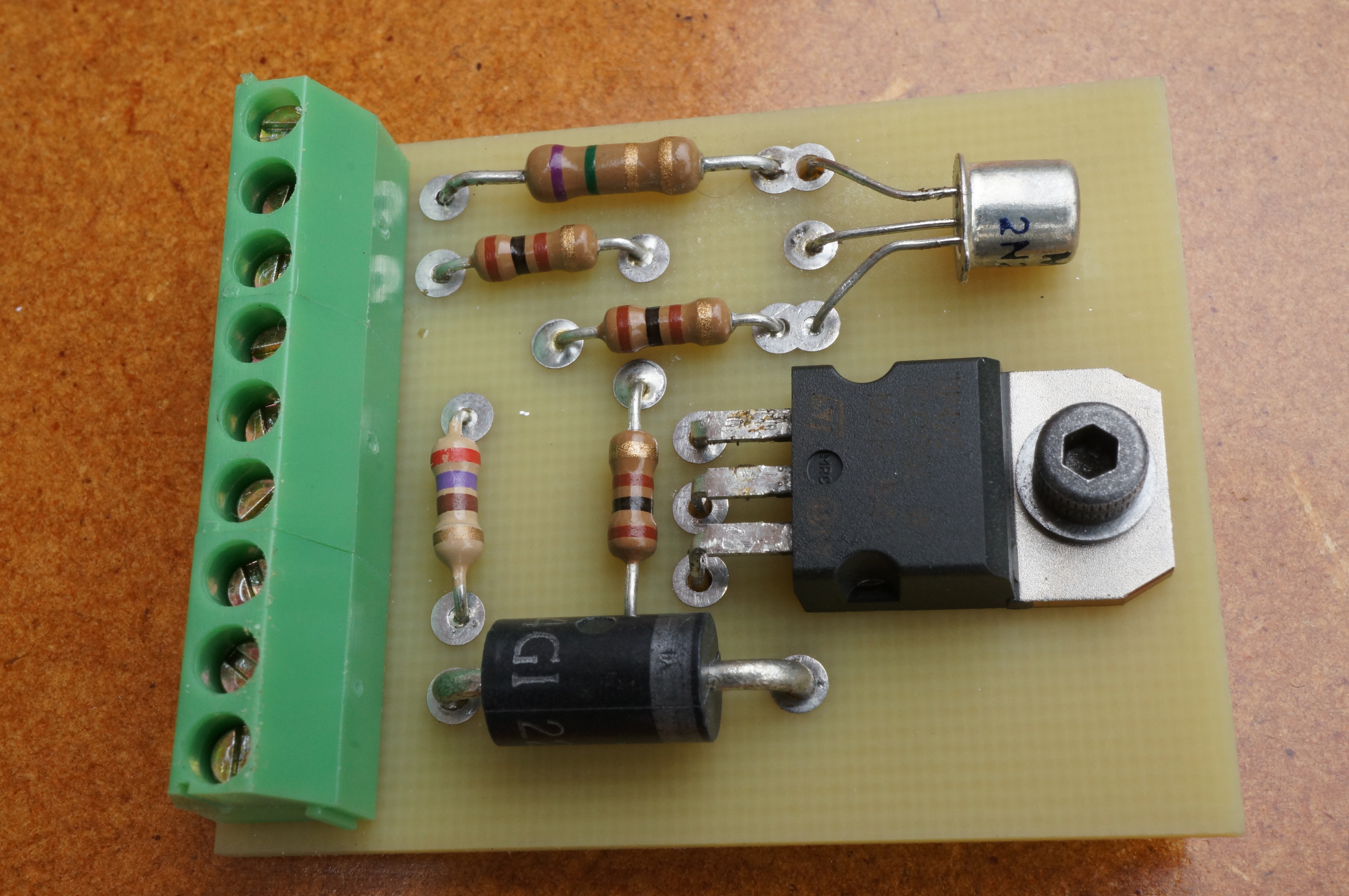
I tapped the power transistor fixing hole in the TIM-6 circuit board for 6-BA. I also had to slightly open out one hole in the board to get the component leg through. I don't get much practice at soldering electronic stuff, and generally approach it with some apprehension, but this went fine. I fitted screw terminals to make wiring easier. (These come with some versions of the kit anyway.)
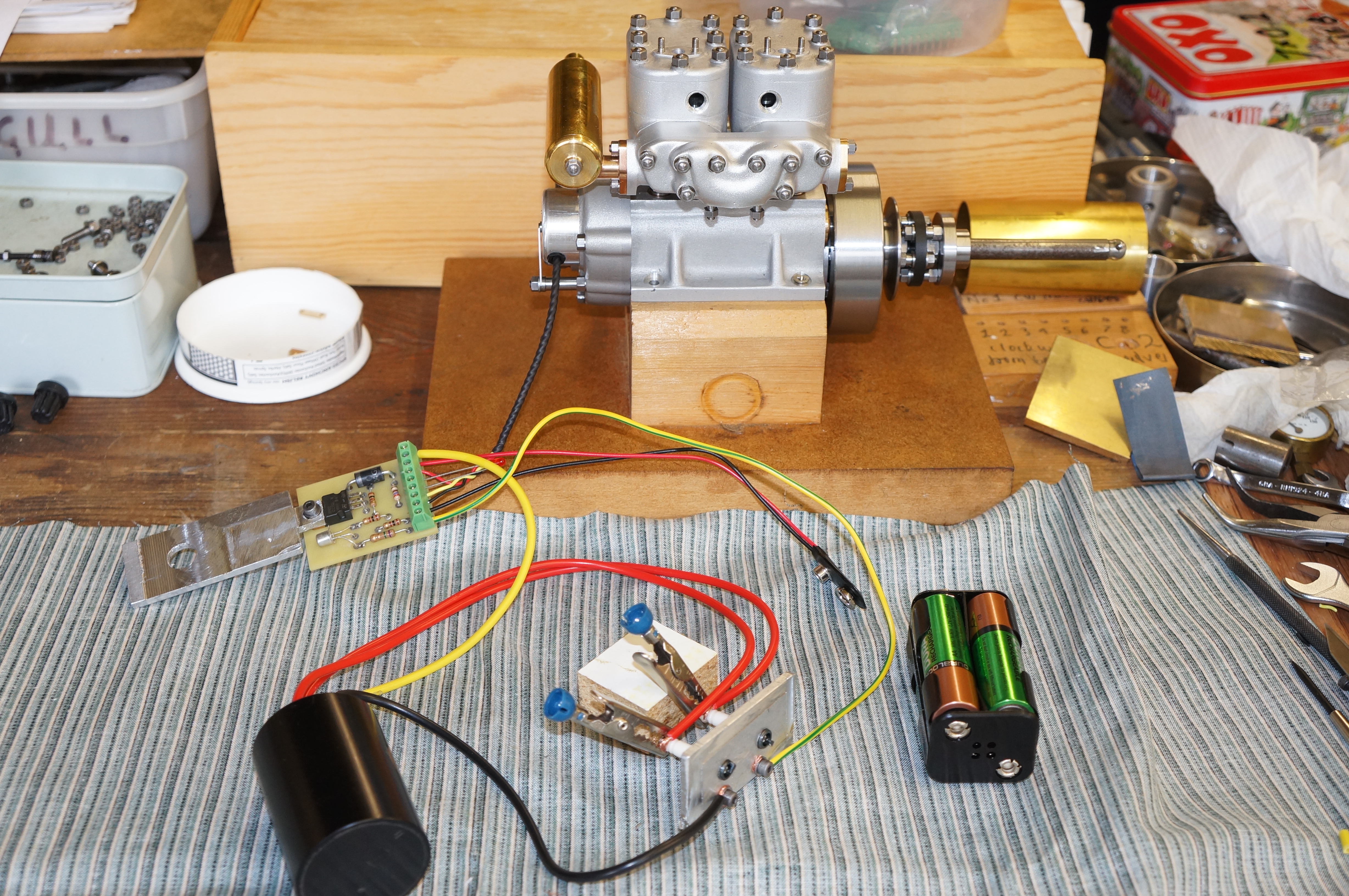
I connected up the Hall sensor cable and LED to the board, and drilled and tapped a scrap of aluminium strip for the plugs and used another piece for a temporary heatsink. I connected a battery pack and the coil for a test. Yes, we have a spark! There seems to be plenty of dwell angle on the sensor too. (4½ hours)
Note: We will discover (when this write-up gets to early 2021) that the Minimag coil is too powerful for the TIM-6 ignition.
.
2020-06-11 – Trying Plug Caps
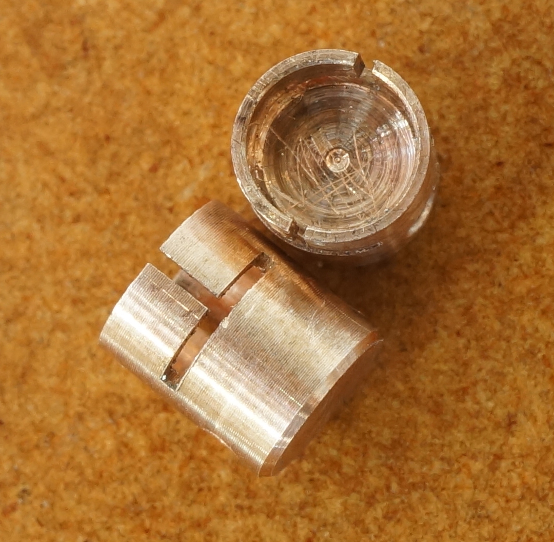
I have decided to have a go at making plug caps, pretty much to the design and instructions by Graham Meek for his Seagull. The insulator is made of two pieces of Delrin, cleverly held together by the brass insert. The brass pieces are very fiddly, and I was not sure I could make them successfully. First, I turned a cap from 10mm rod to ⌀ 11⁄16″, used my spherical turning tool to put a slight dome, 5⁄8″ radius, on the end, and then cut three chamfers for a 1⁄32″ radius on the corner. I sanded the radius smooth, polished, and parted off, then repeated for the second one. Next, I made a sample brass insert to try the fit on the plugs. For this one, I made the slits with a junior hacksaw. I don't have time to try it now. (2 hours)
2020-06-13 – Making plug caps bodies
The trial cap insert does fit, but is a bit too small so the legs get slightly splayed. I need to try it when it is confined inside an insulator. I fitted it into a 4.8 mm hole in a Delrin sleeve. It would not go on to a plug until I put a chamfer inside the lips, and even then it needed too much force. The clip bore will need to be a little bit larger than 5⁄32″.
I faced the cap bodies to length, centred and drilled 4.7 & 4.8 mm to 3⁄8″ shoulder depth and lightly chamfered inside and out. I rounded the edges finely with a needle file and burnished with kitchen paper towel. All this was done at 700 rpm. Next, I set them up for drilling the cross holes with a 7⁄32″ slot drill to give a square bottom hole about 0.015″ short of breaking through on the other side. I managed to confuse myself with the set-up, but the holes seem to have come out central. The entry edge needed delicate deburring to leave a sharp edge to preserve the illusion of the cap being a single piece moulding.
In turning the side, cable entry, tubes, I found that as they are quite long and slender, I was getting a taper over the length of about 0.002″ on diameter. I have used this to my advantage to ease assembly. With one parted off and checked for fit, I turned the second one, drilled, and cut light chamfers and again a polished radius at the edges. After parting off and facing, I also put a small chamfer at the inboard end to ease fitting and to ensure it could be pushed fully home. With the second tube completed, I assembled the caps and set the first one up to finish the hole for the brass insert, drilling up the existing plug hole in the body with a 3⁄16″ slot drill, to cut the radial hole into the inner end of the side tube to receive the brass clip. (4¼ hours)
2020-06-16 – Completing plug caps bodies
After final drilling the second plug cap, I made a start on the brass inserts, turning ¼″ brass bar to 3⁄16″, but found it difficult to get a hole to fit the plugs. (1 hour)
2020-06-17 – Making plug caps clips
Making a second attempt at the clips, I used a tiny boring tool to finish the flat bottomed hole or recess to fit over the plug. I found a diameter of 0.158″ suited the plugs. I parted off a piece long enough to allow it to be gripped while making a second clip at the other end.
For making the slits, I found the 1⁄64″ slitting saw was not running sufficiently true on my existing arbor. Undercutting the existing flange did not help much, leaving the saw still running with a 10 thou wobble. It needs better support. (2 hours)
2020-06-19 – Improving a slitting saw arbor
I set to and made new larger diameter clamping washers, with recessed centres, to give the saw much more support. Working between centres, I turned back the clamping face of the arbor and Loctited a washer in place. When the adhesive had cured sufficiently, I trued up the annular clamping face. On test, the saw was now running with about 0.001″ wobble.
By mounting the clip piece in one of my boring bit toolholders, I was able to cut the axial and lateral slits in the lathe. (3½ hours)
2020-06-27 – Finishing the plug caps and making a heatsink
I have obtained a length of smaller diameter black plug lead wire from Hemingway Kits. It looks much more to scale than the beefy red HT leads on the coil, but it also looks a bit silly dangling out of the oversize holes in the plug caps. Some heat-shrink sleeving over the wire, projecting a short distance from the plug cap looks OK. I trimmed, stripped, and tinned both ends of the wire and smoothed them down to an easy fit in a 1.3mm hole.
With the plug cap clips still on the parent stock, I cross drilled them 1.3mm, but irritatingly not quite square to the slits. I checked the caps with a piece of 3⁄16″ rod, which would push in to about 10 thou short of the nominal full depth. I parted the clips off, faced them to 5 thou short of nominal and put a good chamfer on the top edge, where they will be pressed in. Using the shank of a 1.3mm drill in the cross hole and a piece of shim in the axial slit to get the correct alignment, I was able to push the clips home in the caps. One of them needed a slight tweak in its angular position, using the drill shank poked down the wire hole. The other needed a tap to get the clip to seat.
I made a little silver steel punch to fit, with a 90° point on it, left soft, and used this to swage the clips to grip the wires. That works, and the clips fit very nicely on the plugs. Job's a good 'un, though I say it myself.
I don't think I would have come up with that design, and probably would not have tackled the fiddly manufacture of the clips had I not seen that someone else could do it, so thanks again to Graham.
The TIM-6 ignition board needs a heatsink, and to use a flat plate, a spacer is also required. I milled an alloy spacer ¼″ square by 8⁄long″ and made the heatsink from some matt silver anodised material about 0.05″ thick, sizing it to cover most of the area of the board but clearing the terminal block. (6½ hours)
2020-07-03 – Finishing the heatsink
Just before lunch time I drilled the heat sink and spacer and fitted them to the ignition board. (¾ hour)
2020-10-10 – Making a timing pointer
I want to be able to put graduated ignition timing marks on the timing cover and case, so I need an external engine timing mark. The flywheel is held only on the taper and there is no key or other means of ensuring it is assembled in any particular angular position, so it would be pointless or misleading to mark it permanently. For a temporary solution, duct tape marks well with a ballpoint, so I wrapped some round the flywheel, then took it off and wrapped it in the other direction with the tail of the tape trailing.
I made a pointer out of shim to fit on one of the cylinder studs, but snapped it while bending, so I made and fitted another. I removed No 1 cylinder head, set the engine to top dead using a DTI, marked the tape, then cleaned up the head bolting face, applied fresh Wellseal and refitted it.
With the hall sensor and TIM board wired, the timing light indicated that No 1 cylinder is 1°-1½° behind No 2. I put this down to a slight difference in strength of the two timing magnets. (Two-timing magnets?) This is all I can do until I can run the engine and get an idea of how much advance it likes.
.
Microcontroller
2020-05-24 – Electronic baby steps
This evening I connected the tacho output of the radiator fan to an Arduino Uno microcontroller, which gave me a speed output of 3300, once I had debugged the program. This is the first time I have progressed beyond Starter Kit projects with the Arduino.
2020-06-07 – Fan Control
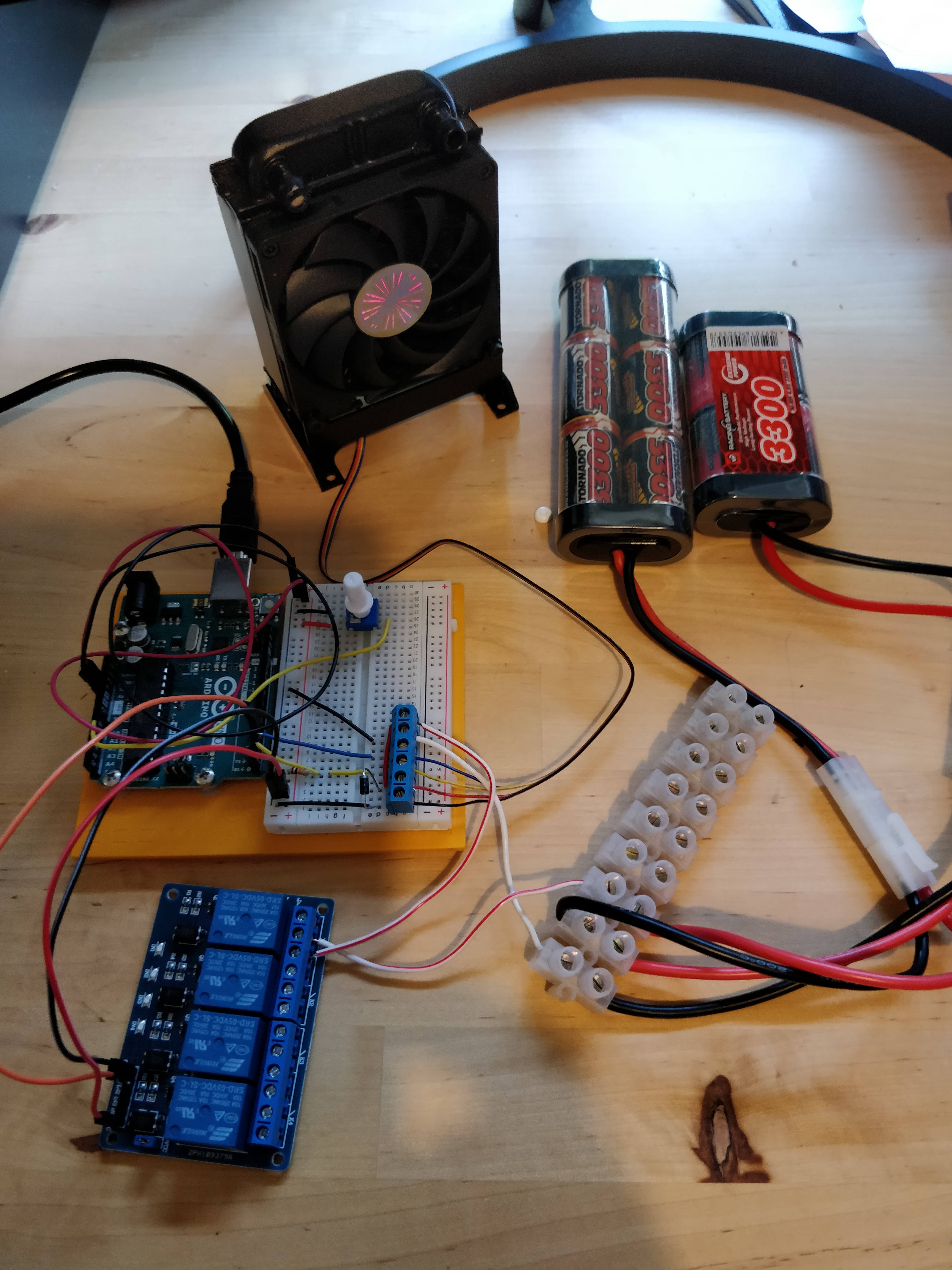
Here I am controlling the fan power with a relay, and its speed with a pulse width modulated signal from the Arduino. A potentiometer provides a variable input voltage to simulate a temperature sensor.
The PWM signal involves some messing about with the internal settings of the Arduino's processor chip because the fan wants its input at 25kHz, and that is much faster than the Arduino's default. The manual for the processor runs to about 650 pages, and I had take my socks off to fathom out enough of the 18 page section on setting up the one of the internal timers (not the clock, but based on it) for 'Fast PWM'. There is also plenty of help on the various Arduino forums. The 'registers' involved go back to defaults after a reset or if the Arduino is powered off, so there is no great risk.
.