
Fabrications
None of the work described here is part of the original Westbury design. I have grouped together all the things that need a soldered assembly. They are mostly made of brass. These are the water pipes, silencer, petrol tank, and three structures to support the engine, tank and radiator.
I have observed some odd things happening while making these assemblies, and I have come to the conclusion that the extruded brass sections have a tendency to shrink axially and grow in cross section at silver soldering temperatures. It seems one should anneal before processing.
Coolant Pipes
I intend to try to achieve neat pipework with swept Y joints, and bolted flanges throughout.
2014-07-24 - Making sample flanges
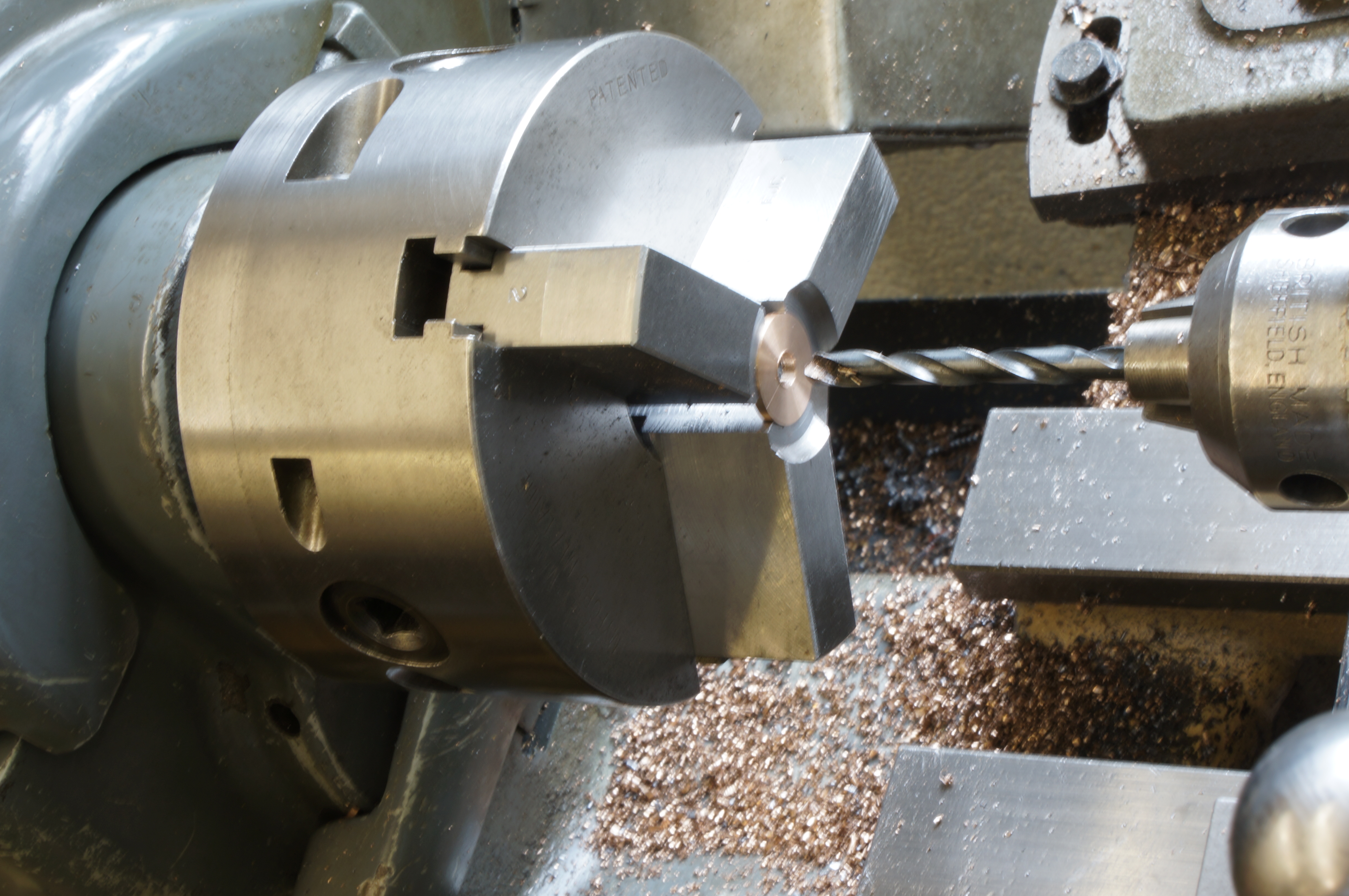
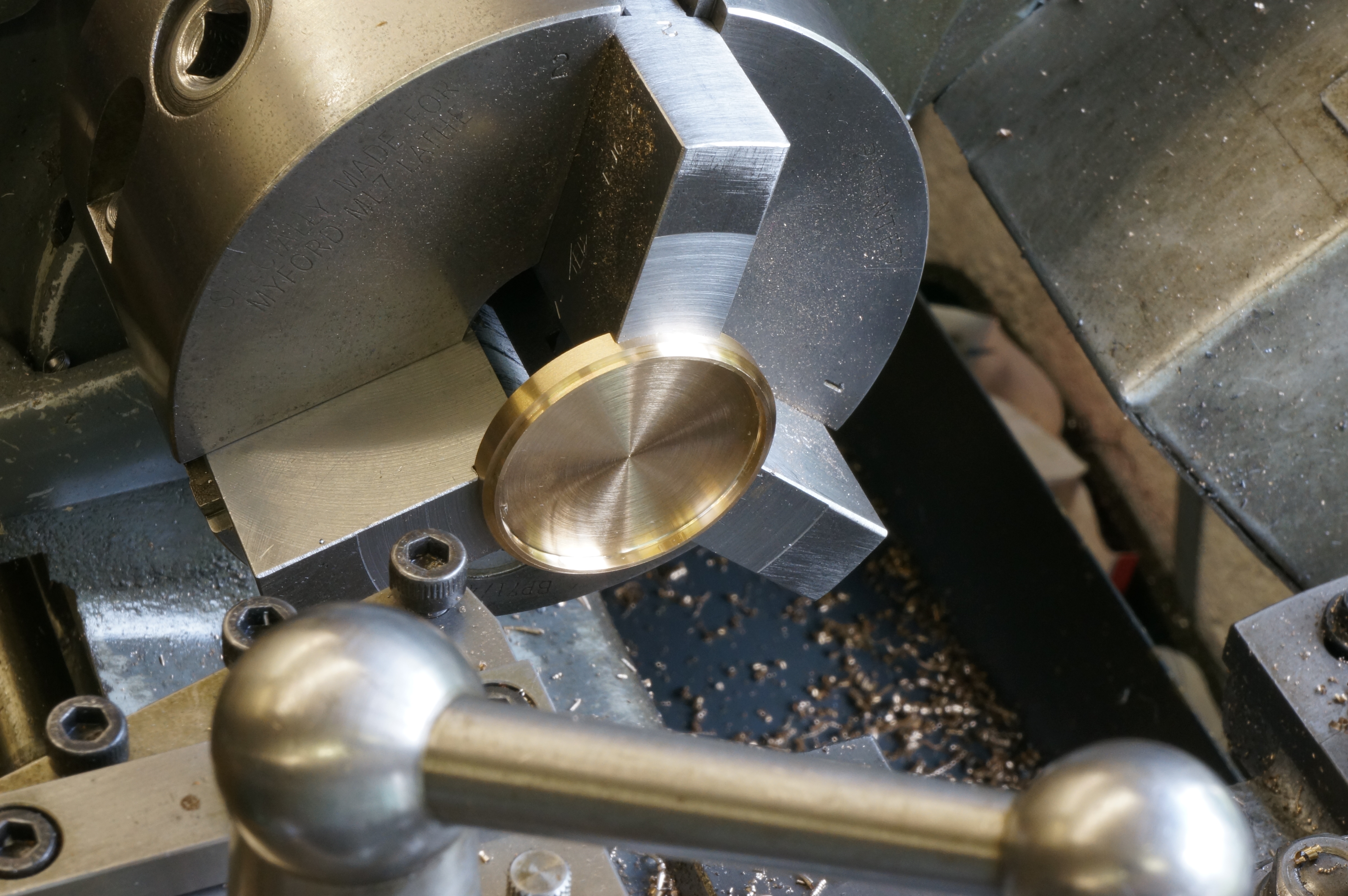
As a break from fettling the cylinders today, I turned a couple of discs for sample water flanges, to help decide on the right thickness to make them. I made one about 0.078″ thick and the other 0.086″. This involved making a narrowed facing tool to clear a step in the soft chuck jaws, so that I could face them to thickness. (1 hour)
2014-08-04 - Making a sacrificial milling plate
After drilling the flange blanks I started work on an aluminium plate to hold the flanges for profile milling. (2¼ hours)
2014-08-05 - Profiling a flange
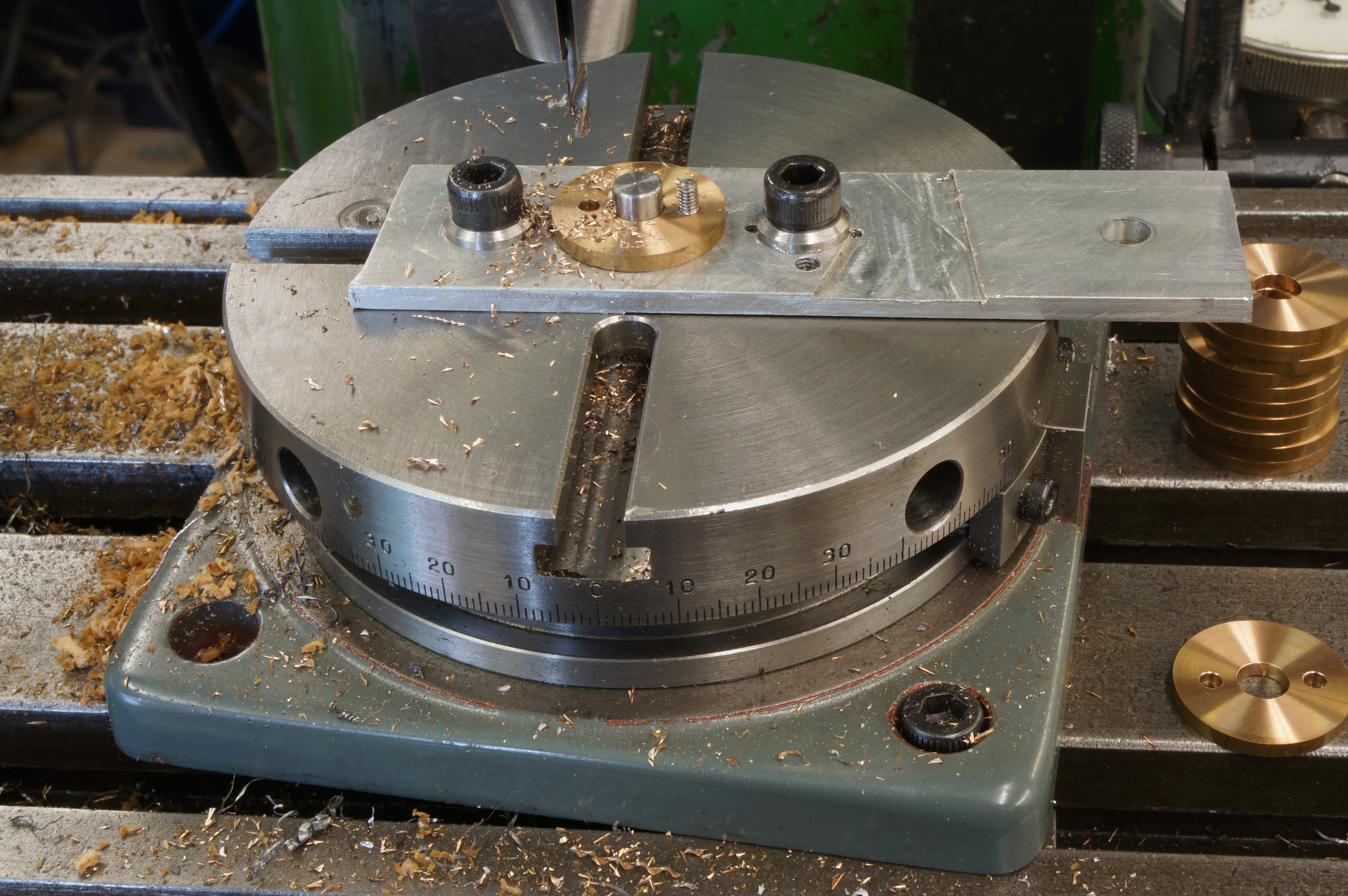
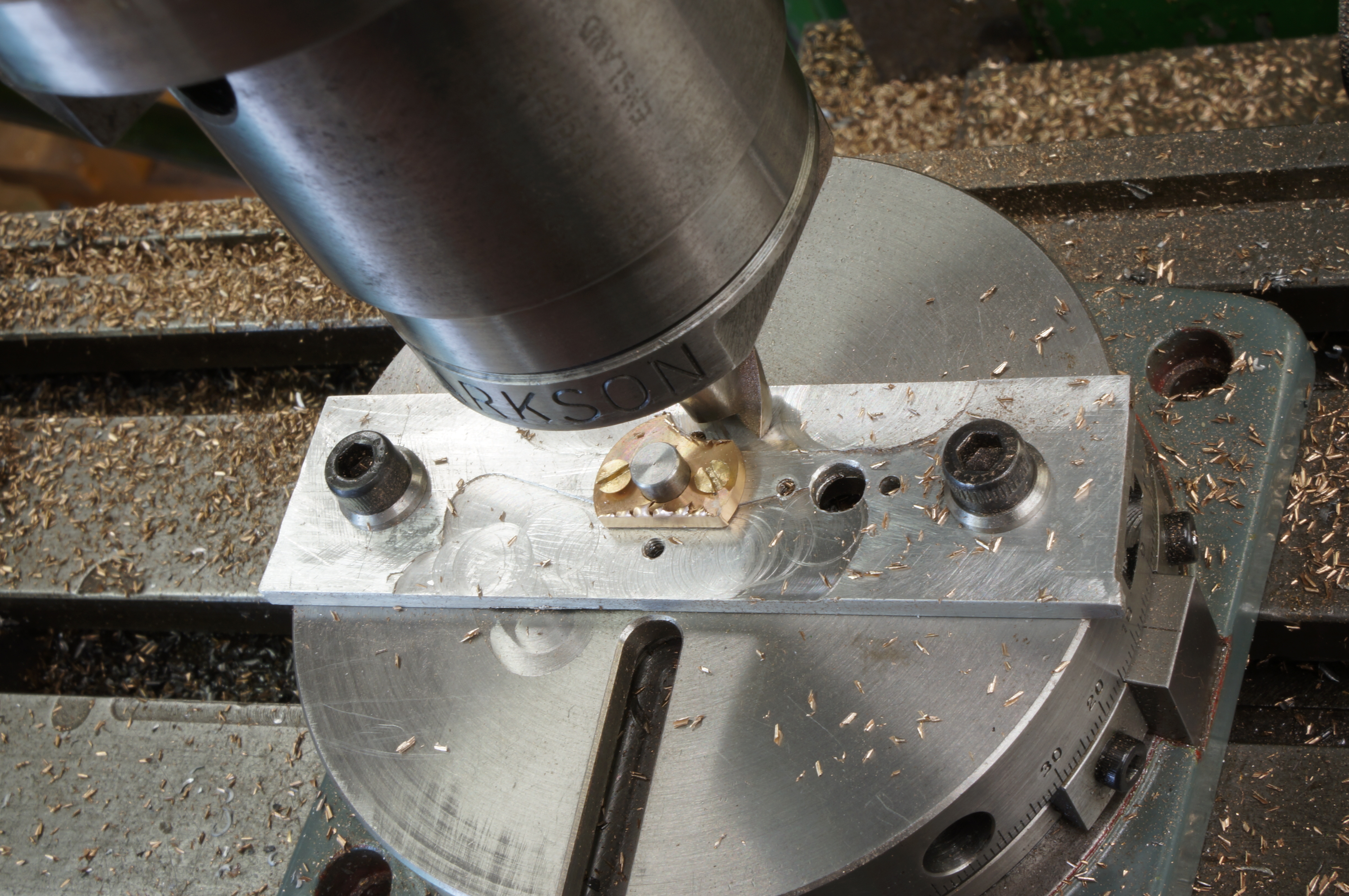
With the plate drilled and tapped, and the central hole reamed, I set up the the plate and the thicker blank on the small rotary table. In cutting the sides I managed to get a jump in the table position and milled too much off one side, and probably did the same again milling the angle flanks. (1½ hours)
2014-08-07 - Finishing the flanges
I achieved a better result with the thinner (5⁄64″) flange by turning it 180° on the jig and machining from the one side to ensure both sides were identical. This is tedious because of the small screws but works well, it came out with a very small allowance for finishing.
Next, I made a pair of 3⁄16″ filing buttons for the bolting lug radii. Using the buttons on the flanges showed that the flanks were not milled to a very accurate angle, but they are good enough for evaluation.
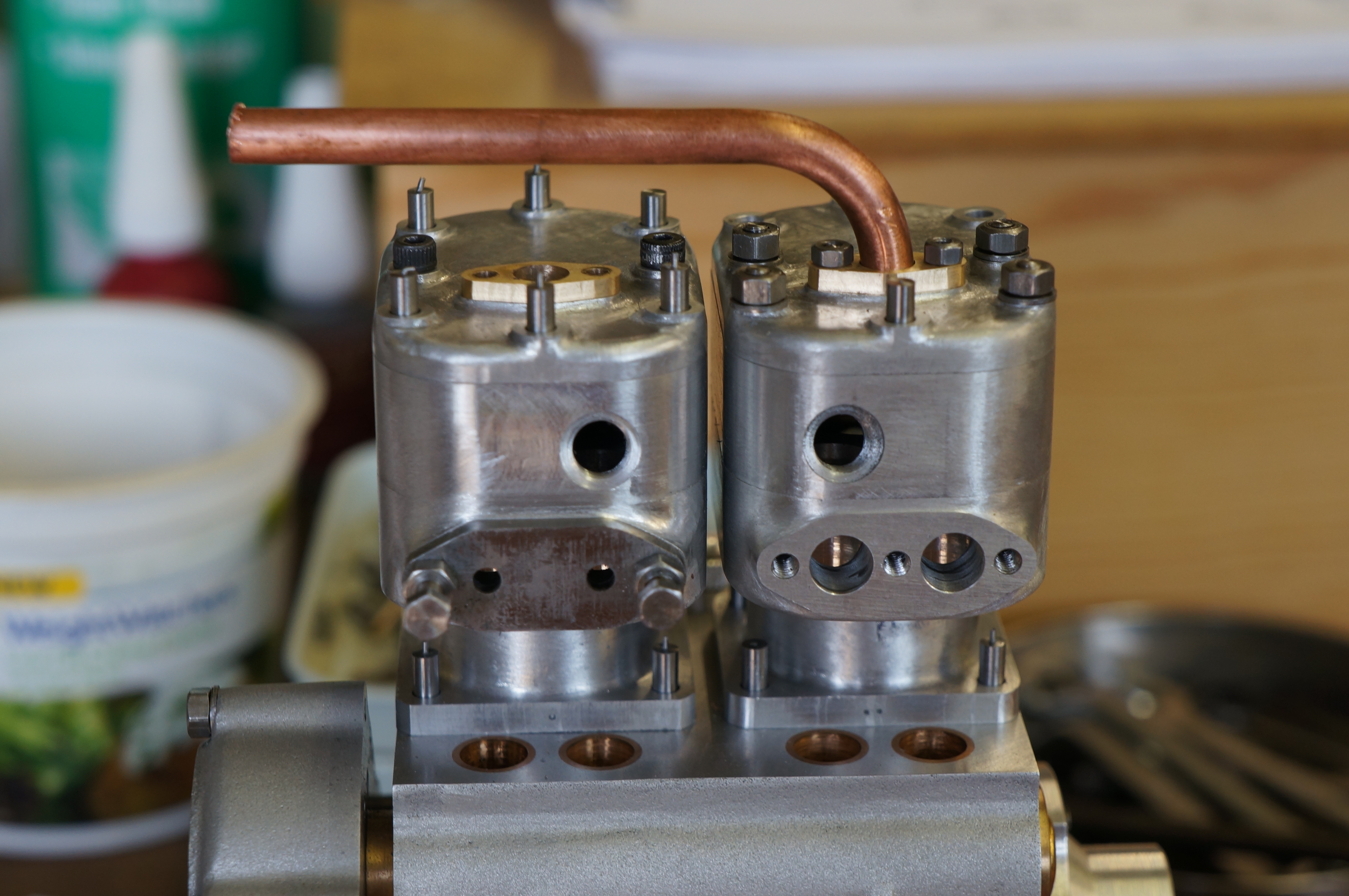
Using a bit of pipe, bent in the newly made pipe bender, I did a trial assembly with dummy studs and nuts. I think the thinner flange looks about right.
2014-08-08 - Silver soldering
I tried silver soldering one of the flanges. I will clearly need a jig for this as the parts cannot be guaranteed to stay put by themselves, especially as the flux dries. Soldering from the back if possible should help to ensure a neat solder fillet on the visible side. Cleaning up after soldering will best be done in the jig too, as the least vice pressure on the tube soon distorts it.
2015-06-06 – Turning flanges
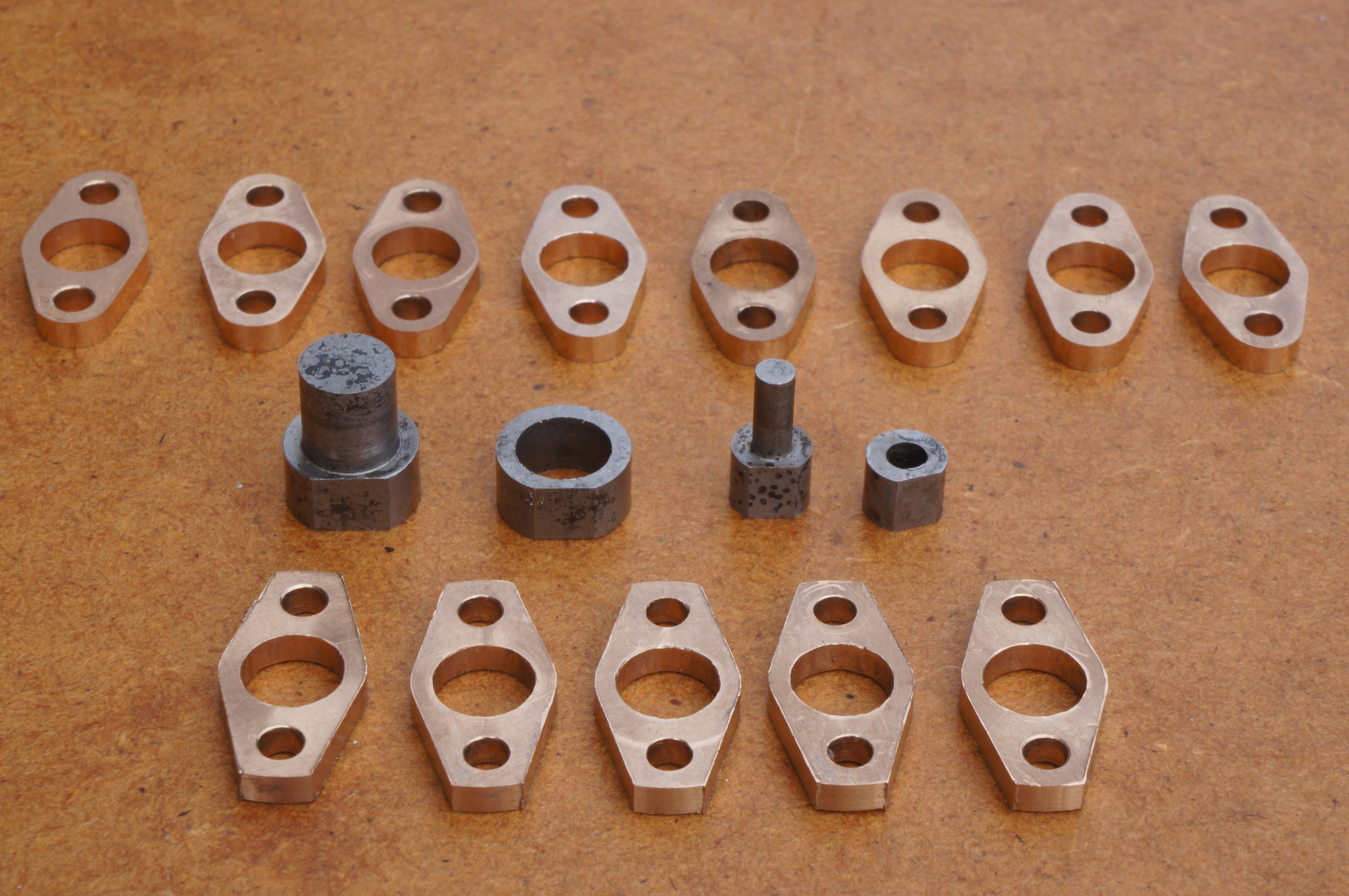
Today, as well as making a start on the silencer, I made 13 bronze discs for water pipe flanges. I parted them off, then faced both sides using soft jaws in the chuck. I left 11 of them 0.002″ over thickness to allow for lapping flat after silver soldering. (2¼ hours on these)
2015-06-13 – Drilling flanges
I drilled and reamed all the flanges to 7⁄32″. (¾ hour)
2015-07-14 – Pipe bending
With the silencer finished this afternoon, I had a little time to make a start on the water pipes. I found the edges of the bender die are too sharp and cut into the tube. (1 hour)
2015-07-15 – Easing the Pipe Bender
I took a shave off the edges of the bending die, and discovered that a fine cut-off wheel in the Dremel is a good way to cut the soft copper pipe without crushing it. I also discovered that setting up the pipes in the soldering jig is going to be tricky. (1¼ hour)
2015-07-24 – Preparing to drill the flanges
I am planning to use the small rotary table for milling the flanges, so I might as well use it for drilling them too. I already have a 7⁄32″ locating pin for the table, but this needed a polish and some of the flange holes had to be eased a little to fit the pin.
First I centred the rotary table on the milling spindle centre and set the dials to zero. An aluminium jig plate already has a milled reference edge which Ilined up. Returning to the zero position I, drilled & reamed a 7⁄32″ hole in the plate and drilled a 2.2mm clearance hole to one side and on the other a 1.7mm tapping hole which I tapped for an 8-BA stud.
I drilled a flange 2.2mm on one side (without a stud in the jig) but found the stainless studs made for them would not fit. Even drilled out to 2.3mm, it would not fit over some. I found an ancient, worn, broken and resharpened 3⁄32″ drill, measuring 0.0925″ would produce a hole that goes over all the studs, but not necessarily a pair of holes that will fit on every pair of studs. These can be adjusted on assembly if need be. I gave the drill,a new 4-facet sharpening. It is short enough to use without centre drilling.
I now have a method. The first hole in each flange is drilled with the flange centred by the locating pin. Then, with a stud fitted in the jig to locate the first hole, the second ones can be drilled, all without moving anything except the parts. The rotary table serves merely as a convenient way to position the locating pin and jig plate. (3¼ hour)
2015-07-25 – Drilling and turning the flanges

Before drilling the flanges I decided to check the mating studs on the engine for accuracy, by measuring over the fitted studs and subtracting the stud diameter. Gratifyingly, they ranged from -0.0005″ to 0.0020″. It is surprising that a 0.0035″ diametral clearance seems to be not quite enough.
After making sure all the flanges pass right over an 7⁄32″ reamer,and making sure the locating pin would fit in the first hole for drilling the second, I drilled 24 holes to complete the drilling stage. I then made a thumb nut and stub mandrel to turn the flange diameters, in batches, to a shade over final size, and picked and rubbed off the burrs. (6¼ hours)
2015-07-27 – Scrapping some
To make flat sides on the flanges I gripped them, four at a time in the milling vice. On the second side of the first batch, with a cut over 1⁄8″ deep, the flanges lifted out of the vice and went in the scrap bin. I had no suitable bar left, but I did have some 1″ diameter offcut discs in thicknesses between 1⁄8″ and ½″. I started roughing them out. (1 hour)
2015-07-29 – Making more
The thickest offcut was large enough to make two flanges, so I parted that, and then faced one side of each flange.
Both of my sets of soft jaws had been used enough times that I could no-longer find a way to seat the flanges for second operation turning. This was not helped by the jaws not having a 120° point. I pressed the cheap Chinese tilting vice into metal working service for the first time in the years I have had it, and milled bevels on all six jaws. I still had to machine quite a lot off one set to get a useable seating for the flanges without the facing tool fouling the jaws. The soft jaws seem to be mostly used for thin pieces like flanges, so I think one day I will fit them with disposable 'shoes'.
Finally, I faced the backs of two blanks, leaving them over size. (3¼ hours)
2015-07-31 – Facing the second side
I drilled and reamed two of the flange blanks, and prepared the other set of soft jaws, with an undercut internal corner. Even so, the flanges showed a thickness variation of up to 0.003″, and I don't know why. (1 hour)
2015-08-01 – Facing again
First I refaced the soft jaws with a short slug clamped near the tips. Then I refaced the discs. They were a lot better, but still not perfect, and two of them have very little allowance for cleaning up after soldering. If they are drilled for the studs in the right place, the thinnest part can be cut away when making them oval. I drilled and reamed the remaining spare flanges, and turned them all to 0.635″ diameter, using the stub mandrel as before. (1½ hours)
2015-08-05 – Drilling and milling
Firstly I set up and drilled the fixing holes in the five replacement flanges. Moving on to the next stage, I rough milled one to about 0.360″ wide, in one pass each side, turning the flange on the jig for the second pass to ensure symmetry. I was unsing an 18mm cutter, and was not getting a good finish, with a heavy burr. (1¾ hours)
2015-08-07 – Milling flange sides
I milled another one, using the self-act. The burr was still ajob to remove. Using a 12mm cutter at 2200rpm, and still using a fairly slow auto feed, the flank finish is much better. I did two in an hour, and the next one in 10 minutes, finishing with 10 done and 4 to go. (2½ hours)
2015-08-08 – Button making
I finished milling the remaining flanges, and then made two sets of filing buttons 5⁄32″ and 3⁄32″ diameter, one of each having an integral locating pin and the other being annular. Because of the closeness of the holes, I milled flats on both sets of buttons, to allow them to be used together. Next I hardened them, and tempered them a little to avoid snapping the delicate bits.
I cleaned the flange holes with a 3⁄32″ reamer and then filed up one flange. I found that the outer edge of the centre buttun had marked the flange a little.(4 hours)
2015-08-11 – Filing
I filed a second flange to the buttons, which took about half an hour. The button shoulder is still cutting into the surface, in spite of being polished up. I tried milling the flanks of the next closer to size, but misread the rotary table protractor, which is marked in four quadrants of 0-45-0 degrees, and which can be confusing. Another for the scrap bin, but I was able to file it up partially, and it proved much easier to finish. So it is probably worth trying to mill the flanks closer to size. I milled another, and dropped it while filing. The small ring button came off and I heard it bounce and roll. Eventually I found it, and finished filing the flange, but I am not very happy with the finish quality.
I milled the flanks of the ten remaining flanges near to final shape, and after deburring them, filed one up. Using a needle file and sitting at a small vice I was able to make a better job. It is close work and quite tiring. (4¼ hours)
2015-08-22 – Much more filing
Over the next couple of weeks I spent most of my workshop time on another project, but filing a flange or two each session. It would be too tedious to report each day. I had them all done by 30 Aug. (4¼ hours in all)
.
2015-08-30 – Preparing pipes
Starting work on the pipes, I cut two pieces for the top, outlet pipe. The long piece I clouted with the Dremel while cutting it off, and the short one I bent so that the down leg was too short. Oh, well - I can use them for working out how to make the Y-joint. I made a trial, cutting with the Dremel and filing to shape, but it was not very good. I annealed the two remaining lengths of pipe. (3¾ hours)
2015-08-31 – Making an experimental joint
I made some collars to hold the pipes in the soldering jig, and they worked well. I soldered the joint and cleaned it up. The result was not bad considering the scrappy joint faces. The assembly is very difficult to hold for cleaning up and requres patience.
2015-09-26 – Making pipe grips
To avoid distorting and bruising the pipes I made a pair of semi-circular shoes for holding them in the vice (1½ hour)
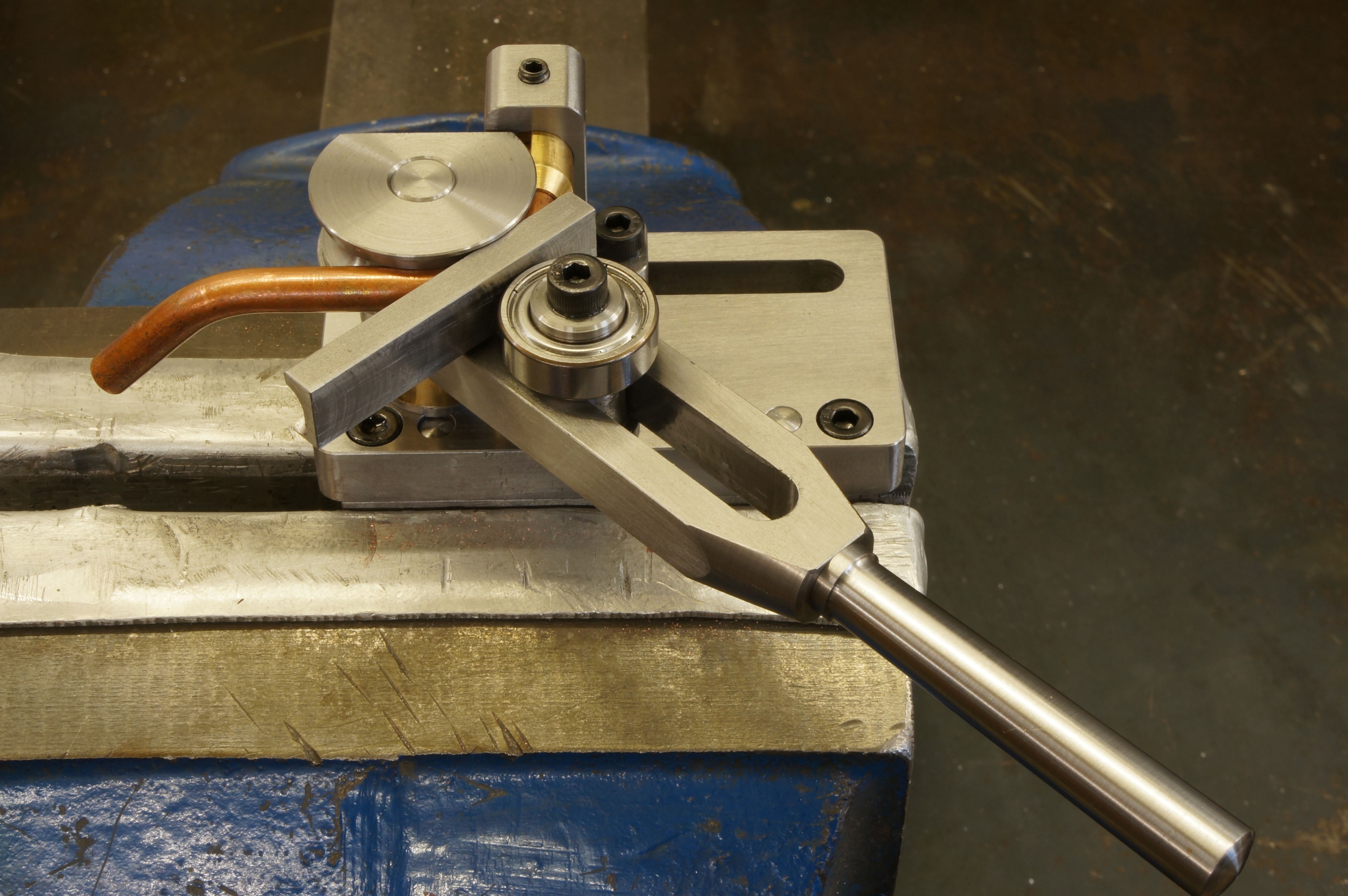
2015-09-29 – Making a joint profile jig
I decided to make a jig for profiling the convex joint face. A brief investigation into the theoretical geometry of the intersection between a cylinder and a torus suggested that the correct shape of the joint line is parabolic. Setting it out with CAD, it appears in practice to be very close to a circular arc.
The jig is a sandwich in which the filler positions the tube and the side plates define the shape of the joint surface. I cut the side plates out of gauge plate and milled them rectangular, milled the filler piece to thickness and drilled and reamed the locating dowel holes, drilled the bolt holes, and tapped one plate. I made the dowels, and machined the guide radius on the side plates and then hardened them. (4½ hours)
2015-10-03 – Bending pipes
The final job on the jig was to mill one corner of the filler to the inside radius of the pipe bend. I started on the wrong corner, but the job finished up OK.
I made a sample convex half of the joint. The jig certainly makes this a great deal easier.
Next, I started bending the pipes, making three good ones but bruising a third. I had to shorten the straight, outside, forming die to allow for the closeness of the two bends on the inlet pipes.
This afternoon, after bending the final piece, I started working on the Y-joints, completing the convex curve on the inlet pipe for No.1 cylinder. The distance between the two bends turned out to be 1⁄8″ too great, but I was able to correct it by adjusting the top bend. (6¼ hours)
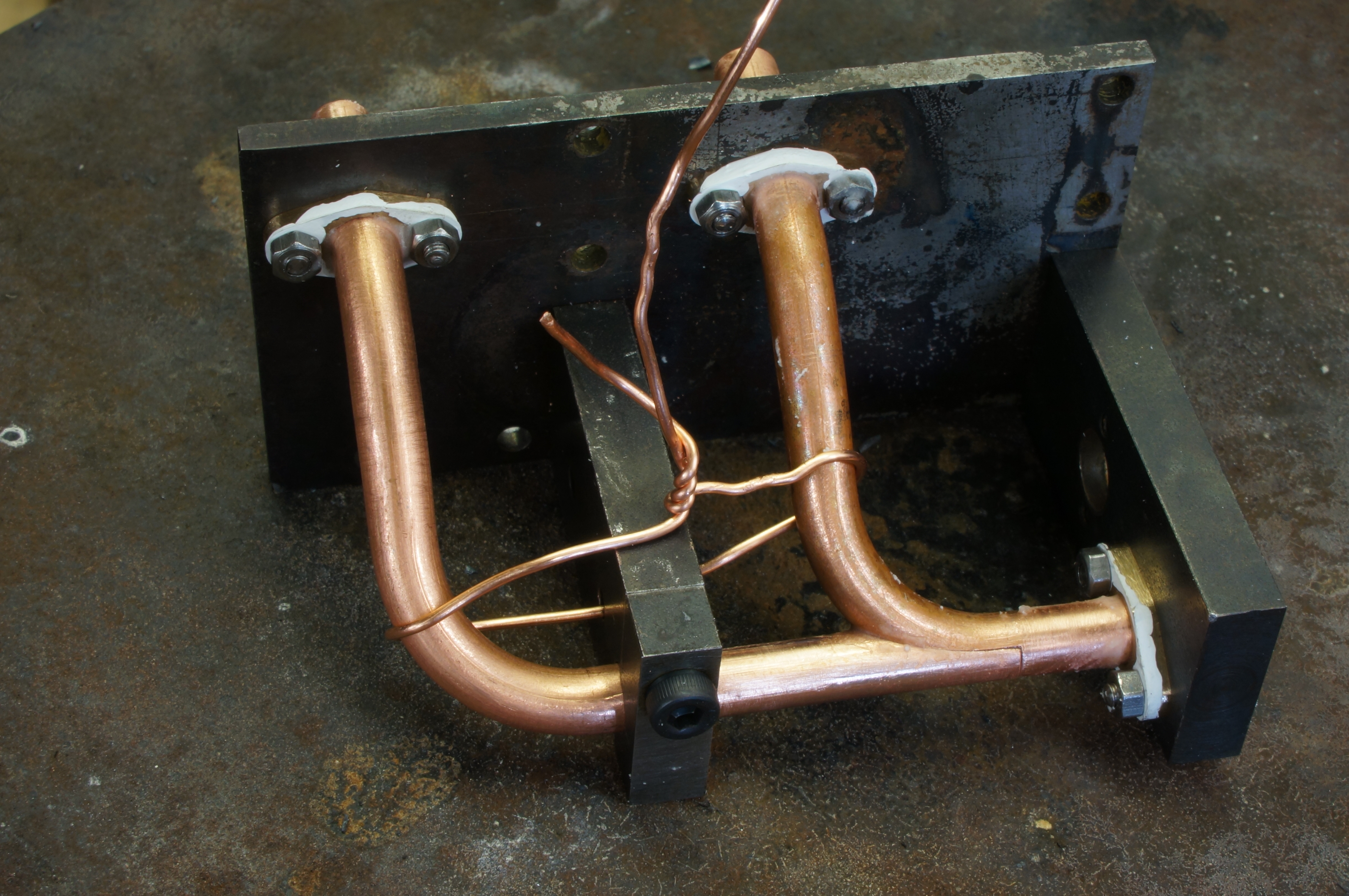
2015-10-06 – Fitting the joint
I tweaked the No 1 inlet pipe a little more so that it now sits in place with a little play. I carried on fitting the joint and adjusting the bends to fit the jig comfortably, getting the parts all ready for soldering. (3¼ hours)
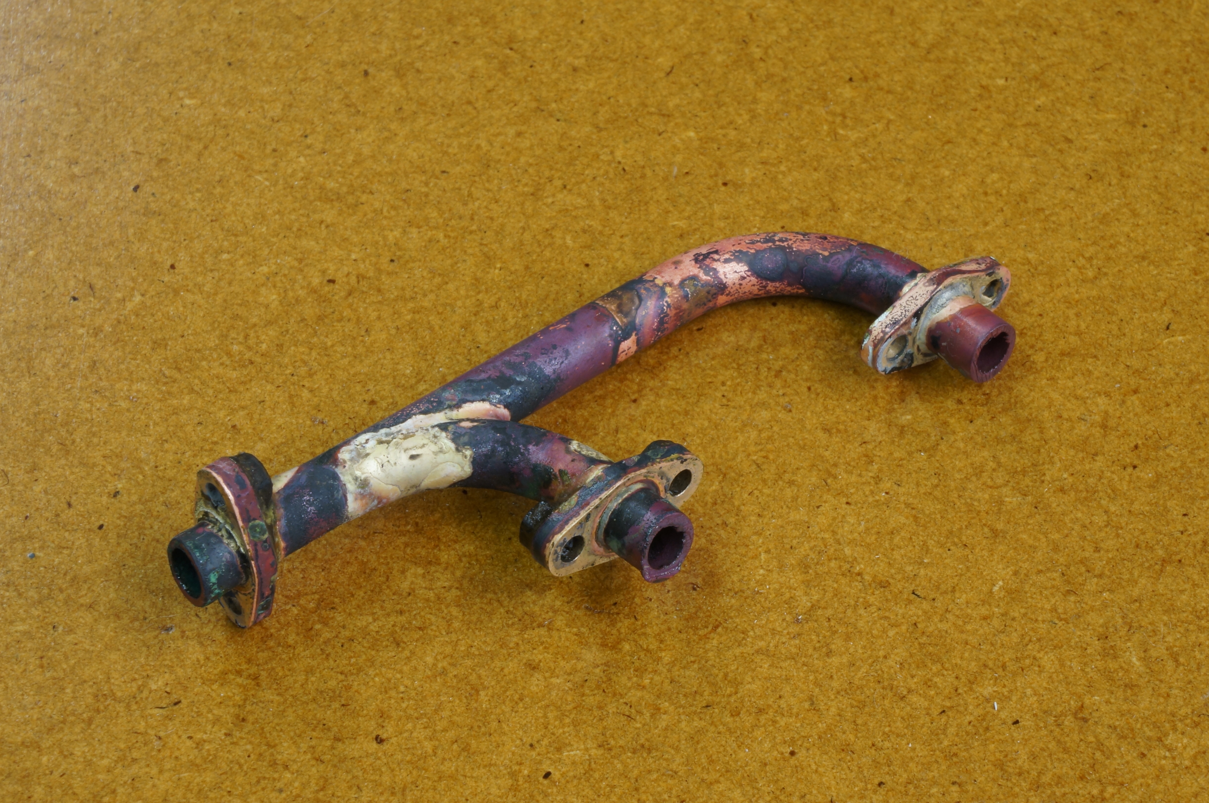
2015-10-07 – Soldering the inlet
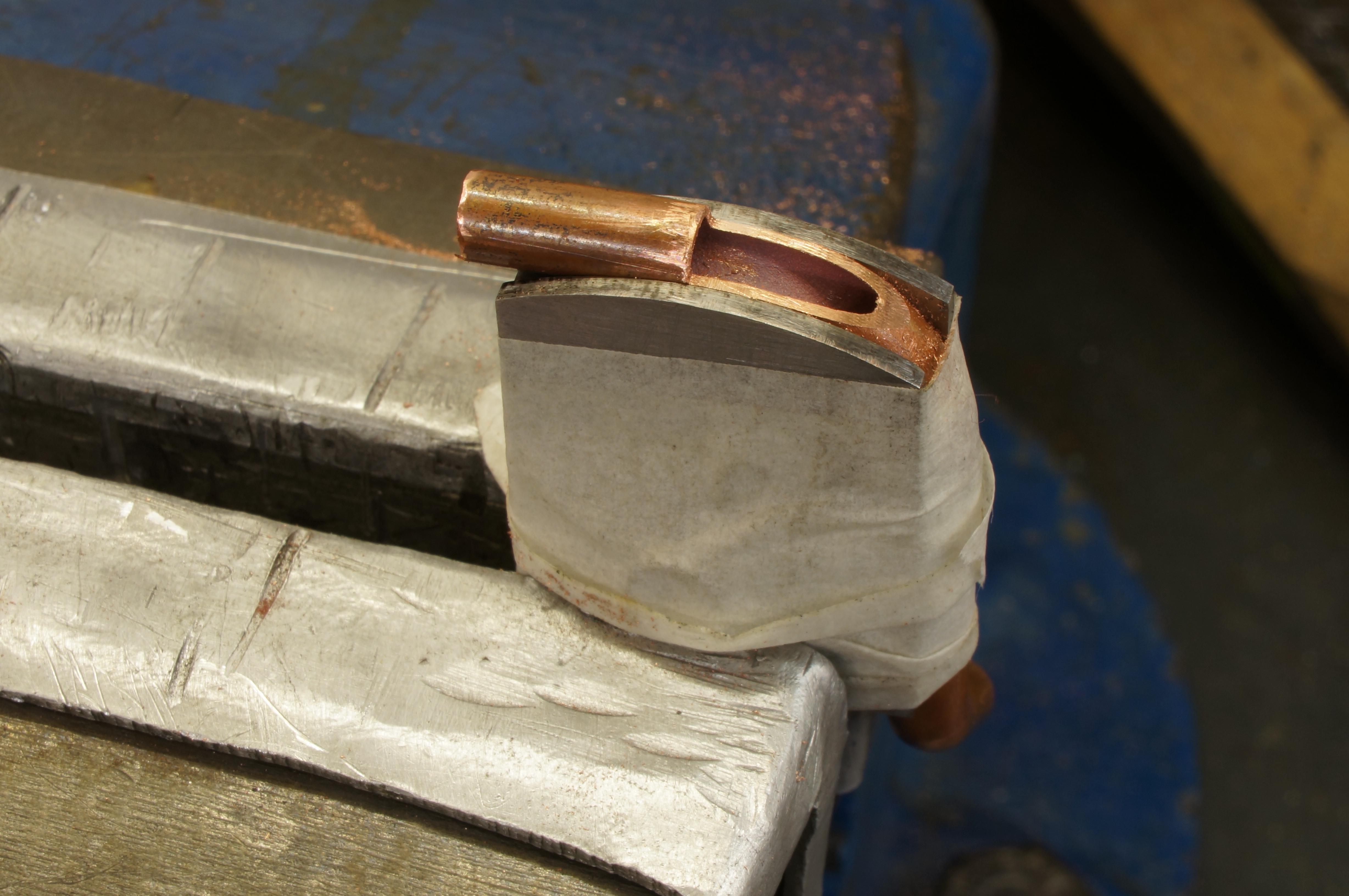
I painted some correcting fluid round the flanges to try to keep the solder off them, and cleaned and fluxed the joints. It felt as though I made a mess of soldering (my notes express it more forcefully.) On starting to clean up it did not look so bad. After lunch I carried on with the clean up. The flanges will need more work. The joint is not perfect but looks OK where it can be seen. (4¼ hours)
2015-10-17 – Preparing the outlet pipes
I filed a satisfactory external radius on the short No 1 pipe, and removed the bulk of the corresponding notch in the long No 2 pipe. The inlet and outlet pipe joints are arranged differently so that the joint is out of view on the underside of each. After more work in the afternoon the joint is now close but sits slightly skewed in the jig. With the short pipe trimmed to project less from the back of the flange, it will be possible to put a clamp over it to hold it in place. (3½ hours)
2015-10-23 – Soldering the outlet

First I tapped a hole in the jig baseplate for a clamp to hold the short tube in place. I cleaned, fluxed and assembled everything in the jig, soldered, and stripped down. This one seems a better job, although I seem to have soldered one of the nuts to a flange. Most of the nut could be ground off quite easily using the Dremel, with which I also cut back the pipe tails. I found that in filing excess solder off the joint, it is very easy to cut into the soft copper.
In the afternoon I removed another nut that was stuck on but not soldered, and continued cleaning up. That file mark will not rub out easily. I also managed to cut into the bolting face of the flange for No 2 cylinder. It still allows a seal, but is noticeable. I am not sure what to do about it.
I rubbed the inlet flanges flat on fine paper on the surface plate and did a trial assembly. (5 hours)
2015-10-24 – More finishing
Today I carried on with the outlet pipe, and flattened the outlet flange face. (2 hours)
Work on the engine now stops for quite some time, as I set about making a camshaft grinder.
2020-10-17 – Finishing the inlet pipe
Back to the pipework today after a long time. The inlet pipe, which I had put aside as a possible failure, still needs more work to see if it is OK. After a bath in sulfuric acid pickle it looks much more hopeful. (¾ hour)
2020-10-20 – Finishing the finishing
After more work filing excess silver solder to clean up the flanges the pipe is finished, for now anyway. It can be fitted now.(1 hour)
.
Silencer
I have been playing with a silencer design for some time, and decided it would be another job I could do to postpone having to make the valves. It has a tangential inlet to a cylindrical chamber with radial holes to an inner, axial, outlet tube. The offset entry is intended to produce a swirling flow in the silencer, with the idea that it ought to more effectively dampen the pulses, it also lifts the silencer well clear of the timing case. I don't know how effective it will be. I can stuff it with wire wool or something if necessary, but I would prefer not to.
2015-06-06 – Turning flanges
I started with a brass turning session, making the silencer inlet pipe and flange, two silencer end flanges and turning the blanking plate for the other end of the exhaust manifold. (1½ hours)
2015-06-12 – Making end caps
I made two inlet end caps for the silencer, making the central boss too small on the first and doing exactly the same thing on the second. (1½ hours)
2015-06-13 – Making end caps
If I use a one-under-size nut to hold the silencer together, the second of the flanges will be OK. After mangling an outer end cap while trying to hold it for second operation turning, I made a good one from the first of the inlet end flanges. (1 hour)
2015-06-16 – Drilling the silencer tube
Using a short stub mandrel turned in situ, I rounded the corner on each silencer flange. I then made the offset entry hole in the silencer tube, badly. I decided a longer tube would be better anyway, and cut and faced a new piece to 2½″ long. While chewing over how to make a better job of the side entry hole, I cut the inlet pipe to the correct length. (4 hours)
2015-06-18 – Jigging the silencer tube
After realising that the water pipe jig would be a good basis for a silencer jig, I cut a piece of steel for the job, but then decided I would do better to get the design on paper first.
I had intended to finish the oval flange profile and mounting holes after soldering, but if the job is jigged it would be easier to make the flange before soldering. With this in mind I set up and drilled the mounting holes in the flange, seting the holes from the circumference and forgetting that that circumference is currently left 0.009″ over size, so the hole positions ended up offset. Scrap.
I turned up a new inlet flange & tube using up a piece of gunmetal. As I intend to paint the silencer black, this should not matter. I also drilled the bolt holes in the blanking plate that goes at the flywheel end of the exhaust manifold.
I set up the small rotary table in the milling machine and centred it in line with the spindle. With a sacrificial aluminium jig plate fixed to the table, I drilled & tapped mounting holes for the flanges. The parts are tight fit on the jig, but are OK.
In milling the flanks of the oval flange profile, the Autolock chuck came apart, gouging a bit out of the little rotary table that I had put a great deal of care into making, and doing slight damage to the chuck threads. The rest of the day's work was spent failing to get the chuck to assemble nicely. (4½ hours)
2015-06-19 – Finishing the blanking plate
Using a 1″ cut-off disc in the Dremel, I was able to dress the bruised internal thread in the Autolock chuck body. The chuck now assembles without binding. This device may well automatically tighten the collet on the cutter shank, but the sleeve definitely needs a biff on the wrench to ensure it is tight against the body. Which is what I forgot to do. I think it unscrewed when I turned the spindle motor off.
Incidentally, most people insist on an incorrect procedure for using an Autolock chuck. They are told to leave the sleeve backed off half a turn, tighten the cutter against the centre and then tighten the sleeve with the wrench, leaving a small gap. This is not what the instructions say, is a complete misunderstanding of the mechanics of the chuck, is likely to cause the damage one often finds to the important centre up inside the chuck, and relies on the thread for the true running of the cutter.
To mill the silencer inlet flange profile I first milled straight across on each side, turning the part on the jig to ensure symmetry, and producing a width of 0.4975″. This means there is exactly 0.030″ to come off each side. I set the angle stops on the table and milled both flanks. One angle was not quite right, but I had left sufficient for file finishing with buttons.
After tweaking the rotary table stops I milled the blanking plate. Again I filed the radii to buttons, then lapped the faces and then gave the outside face a straight line rub on 1200 grit for a fine textured finish, and fitted the piece on the manifold. (3 hours)
2015-07-03 – Resuming the silencer jig
Moving back to the jig, I milled the ends of the mounting plates square and to length, and cut the hole for the silencer tube using an end-mill. This hole is perhaps a bit tight. (2¼ hours)
2015-07-04 – Continuing the silencer jig
Today I spent most of my shop time on a storage rack, but also drilled holes in the jig baseplate and one of the existing posts.(¾ hour)
2015-07-05 – Continuing the silencer jig
Between being repeatedly pestered by the junior dog to play ball, I managed to finish drilling and tapping all the remaining holes in the jig. (1¼ hours)
2015-07-07 – Using the silencer jig
Once the new posts were slit on one side for clamp screws, the jig was finished. I used it first to make the offset hole in the silencer tube, and then to silver solder the tube and inlet together. It soldered and cleaned up nicely with a good joint line and little spread. However, the jig posts were difficult to get off and left the tube squashed a bit. This will have to be rubbed out. I had forgotten the 6-BA cap-head would be trapped after soldering, and had to sacrifice it. (3 hours)
In retrospect, I suspect that heating the extruded silencer tube caused it to grow in diameter (and shorten in length). This might well be explained by relaxing internal stresses from the extrusion process.
2015-07-08 – Finishing the tube
Today I bored out the unwanted part of the inlet tube projecting inside the silencer tube, leaving a small lip all round. I also sanded and polished out the blemishes on the outside of the tube. (1½ hours)
2015-07-10 – Soldering the exhaust tube
I made a spacer to position the outer flange on the exhaust pipe for soldering. I turned the tube to length and drilled the cross holes with a deliberately uneven pattern to mitigate possible resonance. I made a plug to fit the inlet end of the exhaust tube, deciding at the last minute to make it with a locating shoulder, but forgetting to shorten the tube to correct the length.
In soldering the inner assembly, I melted the plug slightly, and the flange is not quite square either. After cleaning up, I turned the flange to fit the outer tube. I think it will be OK. I turned the end of the plug away, restoring the correct length of the inner tube. It seems to still be well soldered. (4½ hours)
2015-07-14 – Finishing the silencer

Because of the considerable amount of dressing I had to do on the outer tube, the outer flange was standing proud of the tube surface when fitted, so I turned five or six thou. off the diameter to remove the ridge.
With the tube chucked for this operation it was running true, so I set the top-slide round to 3° and bored a flare in the outlet end, out to about 0.275″ diameter at the edge. This thinned the pipe to a more scale appearance. In theory this would also reduce the exhaust back-pressure, but I tried applying Bernoulli to some big assumptions and concluded that the effect would be minuscule.
I drilled and tapped the plugged end, made a stud to fit, and assembled the finished silencer. (2 hours)
.
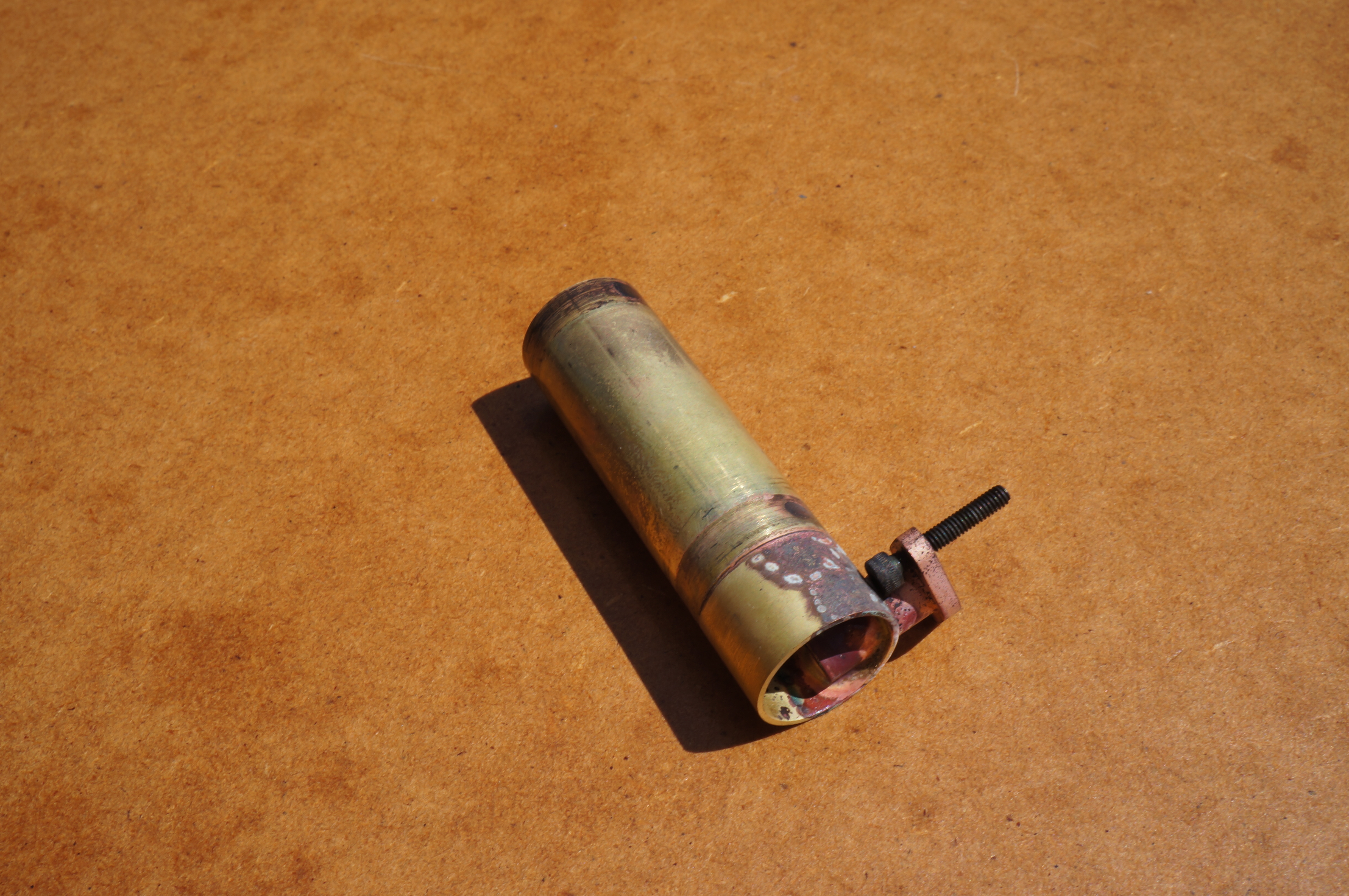
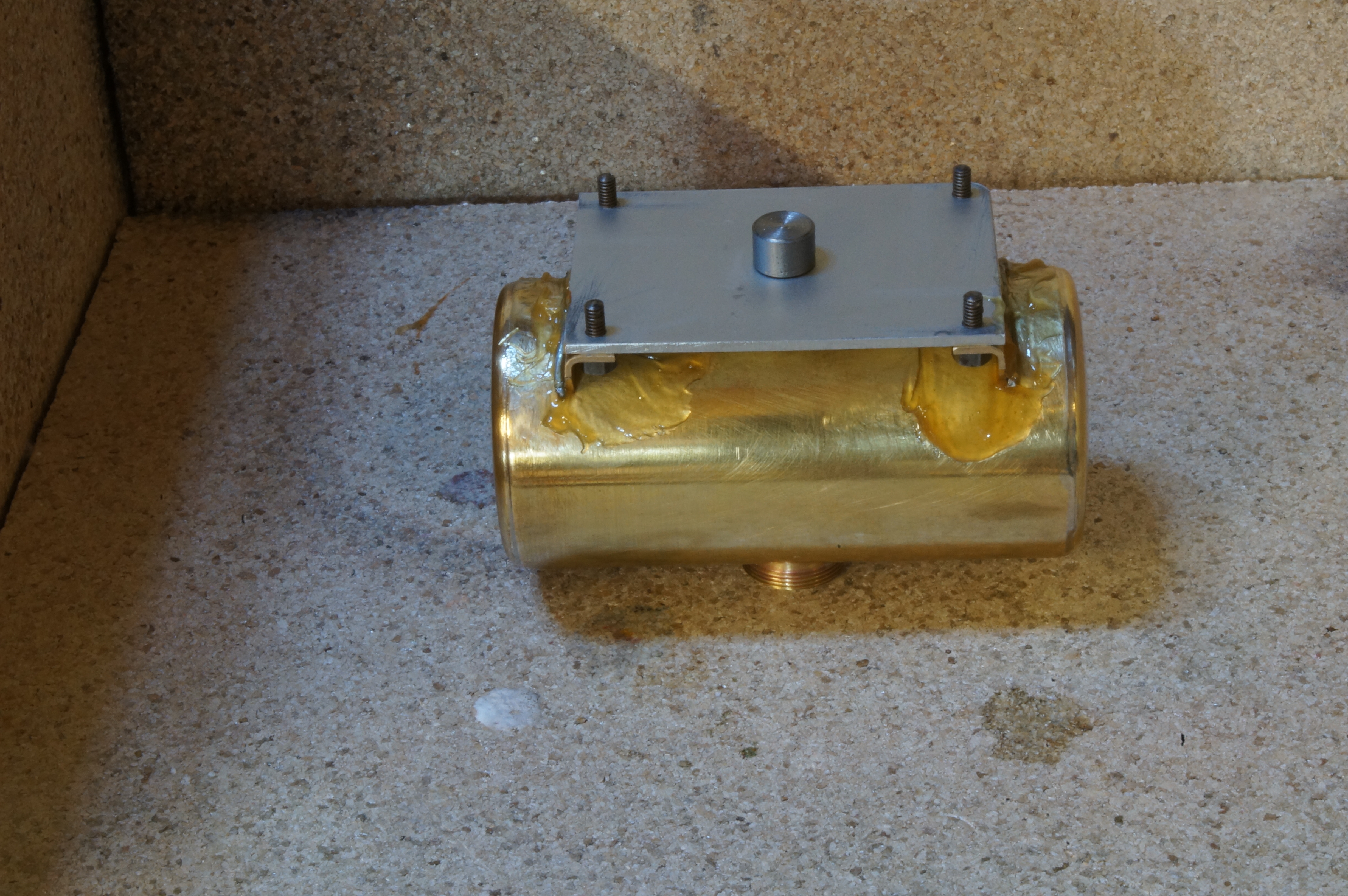
Petrol Tank
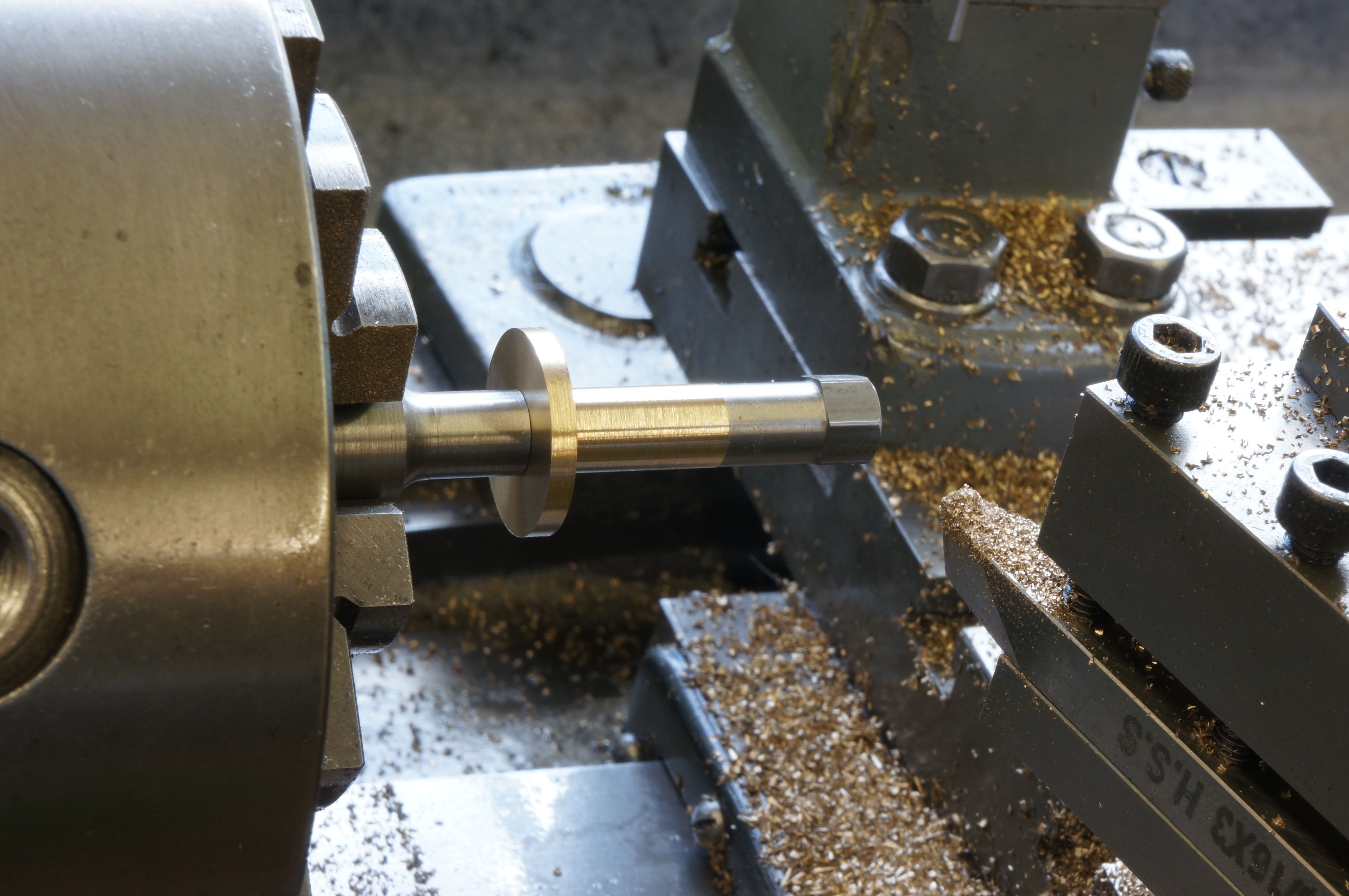
2017-08-26 – Turning the ends
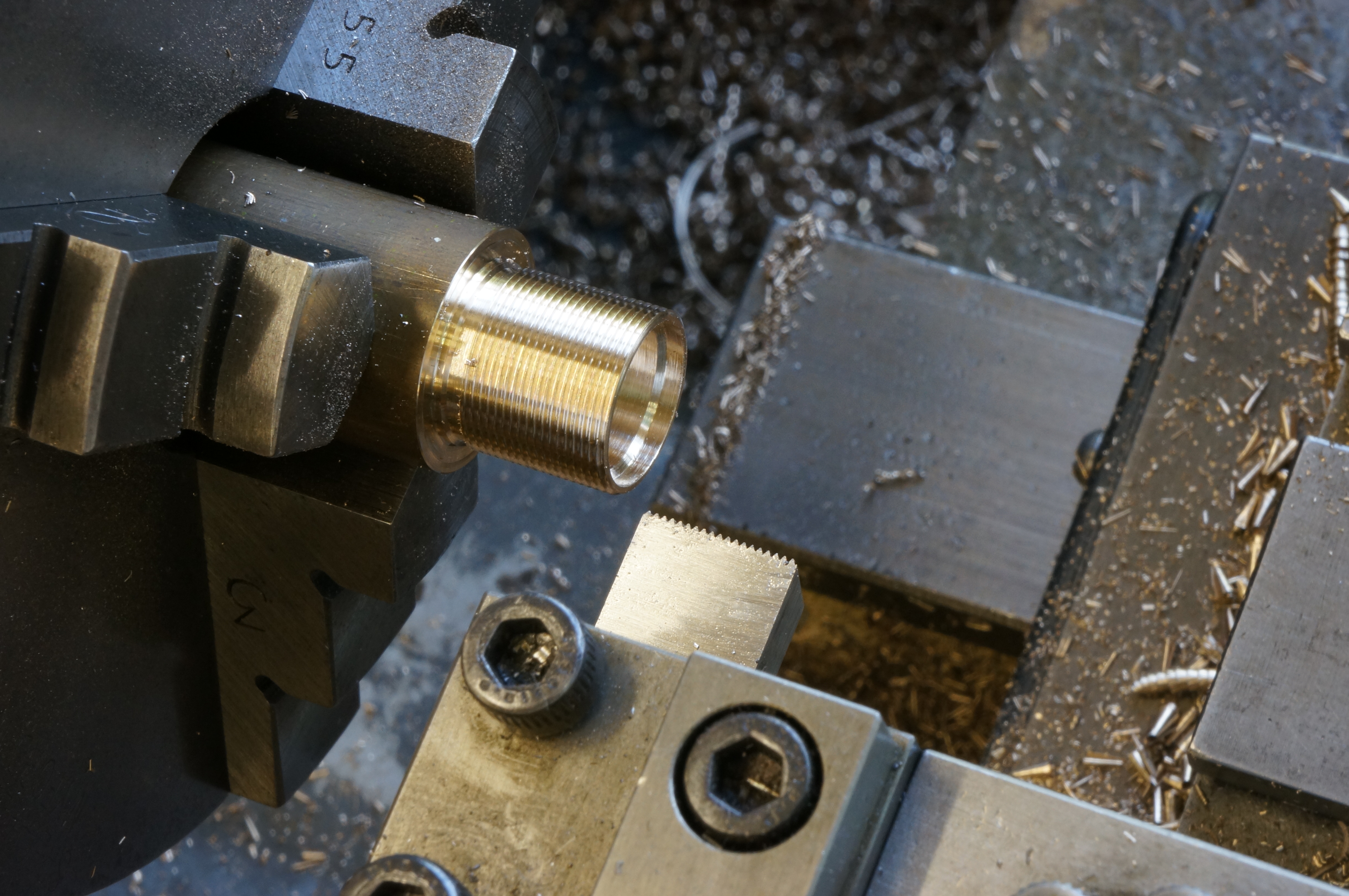
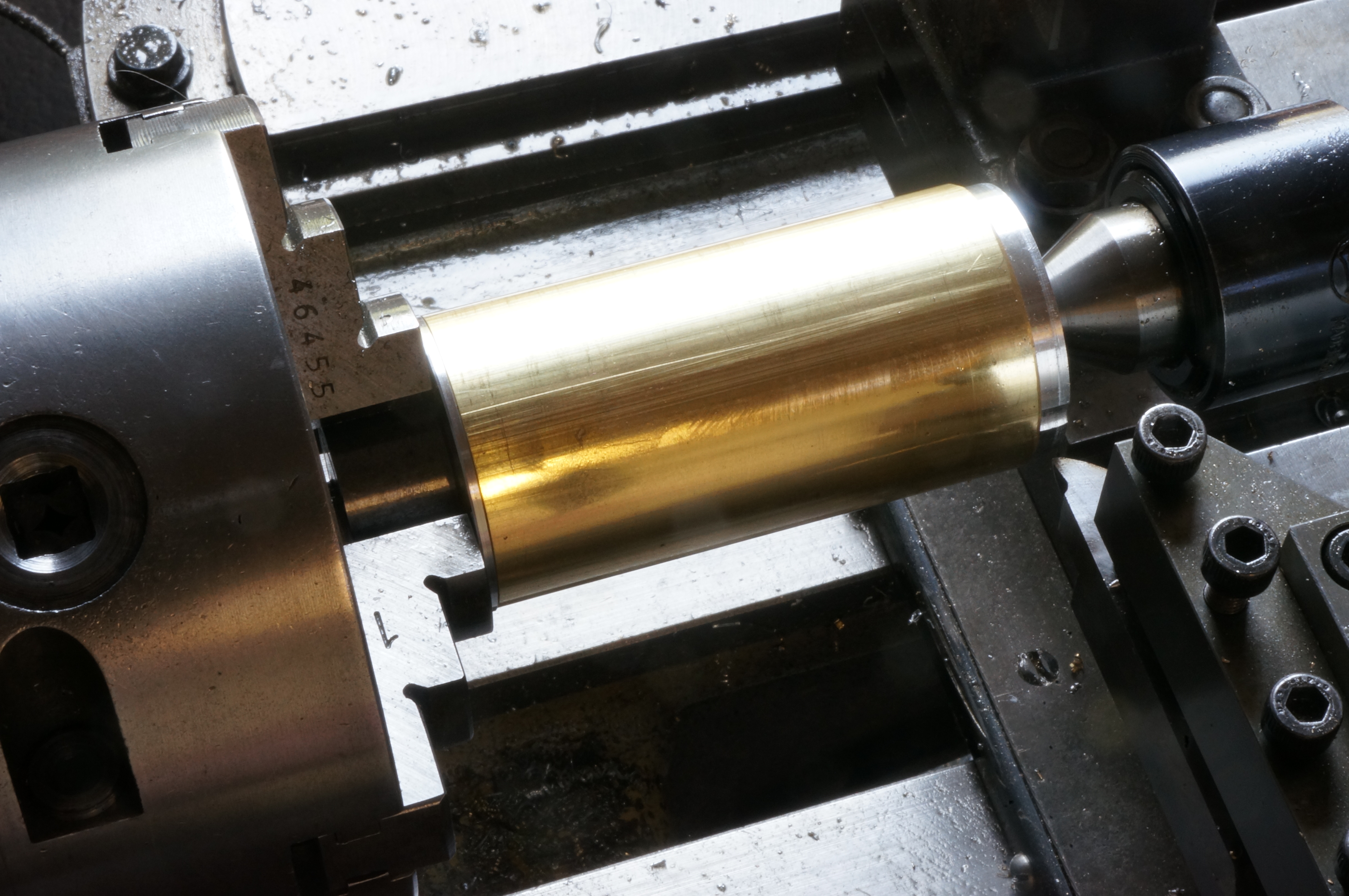
In a couple of brief sessions in the shop in early July I turned the ends of the brass tube for the tank, and cut out two pieces of brass plate for the end caps. I started today by giving the lathe a good clean, which I generally do before a brass session, so I can start with a dry lathe and tray. I set up each tank ends and bored the internal recess to form a flange. Then, gripping by the recess, I rough turned the outside diameters and faces. I ground a tool with a sharp corner, and as a third operation in soft jaws, turned the shoulders to a 1.430″ push fit in the tube. This does not leave much to grip them by for doming the outsides.
Finally, I turned, bored, and threaded the filler neck. (5½ hours)
2017-08-29 – Completing the Filler Neck

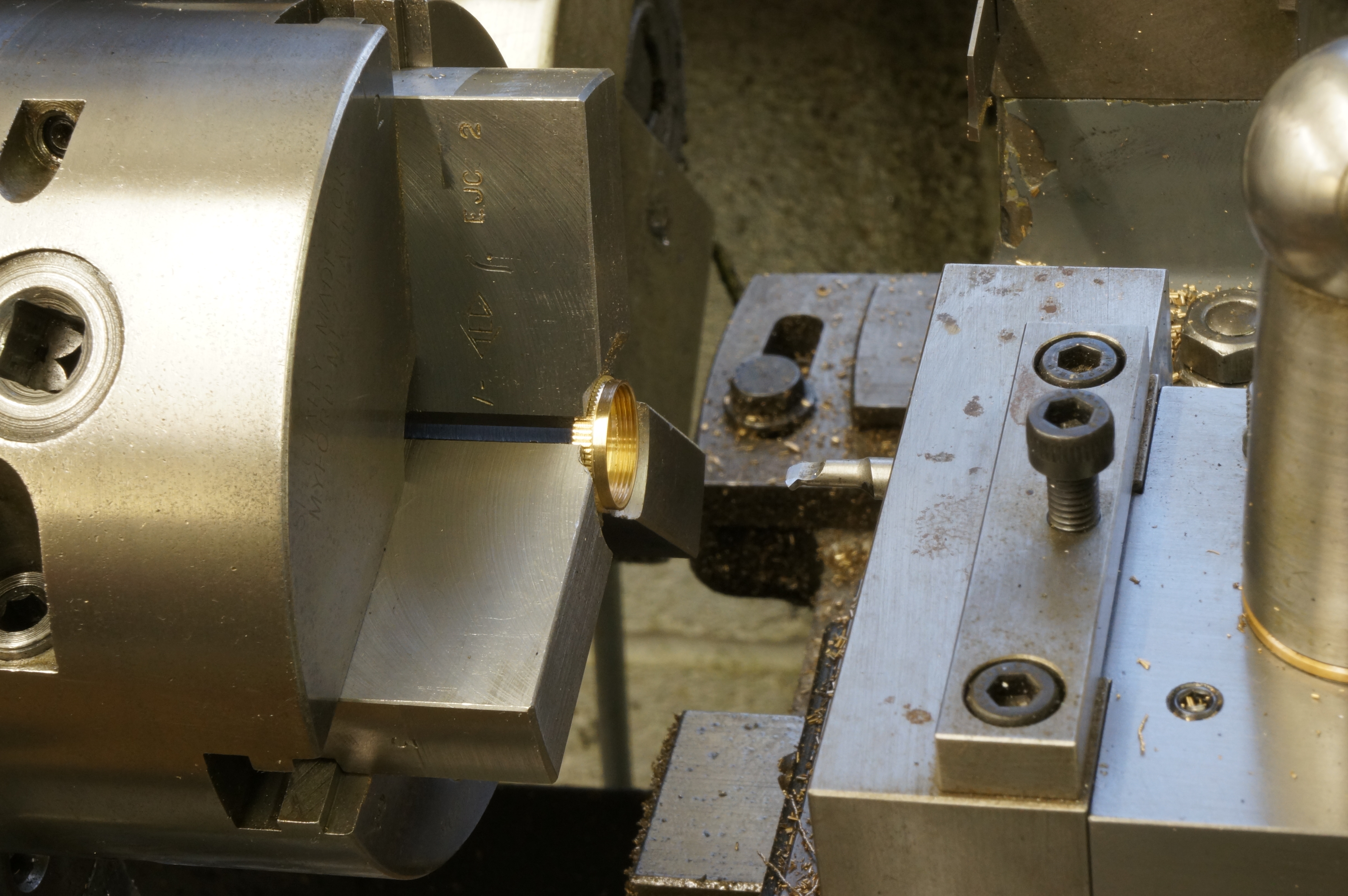
I turned away the centre portion of the thread to produce the diameter that seats against the tank, then parted the filler off and cleaned up. I then parted the remaining threaded portion with a bit of the bar to make a gauge for fitting the cap thread. Next, I faced and turned the cap, and shaped the 'knurled' grooves. As it is brass, I decided to cut the grooves in one pass. This resulted in a fine but very regular chatter pattern. I bored soft jaws to fit the cap
2017-08-31 – Boring the Tank Cap
I bored out the cap ready for threading and cut the lead-in chamfer at the edge. For cutting the thread I need to make tiny boring tools for an undercut at the top and for screwcutting. These will be hardened silver steel, and I have run out propane. (¾ hour)
2017-09-02 – Threading the Cap
Having made several boring bits from scratch this morning, I tried them without tempering, as I was working with brass. The internal undercut in the fuel filler cap went OK, but threading did not, resulting in a chipped tool and an unsatisfactory thread that would not screw on properly despite being loose. (4¼ hour)
2017-11-04 – Doming the End Caps
During October, I made another tool on the to-do list: a large radius tool. With this I was able to complete the tank end caps by turning to diameter, cutting the dome, and forming the corned radius to simulate a pressed tank end.
Among other jobs I also made the tank outlet bush.
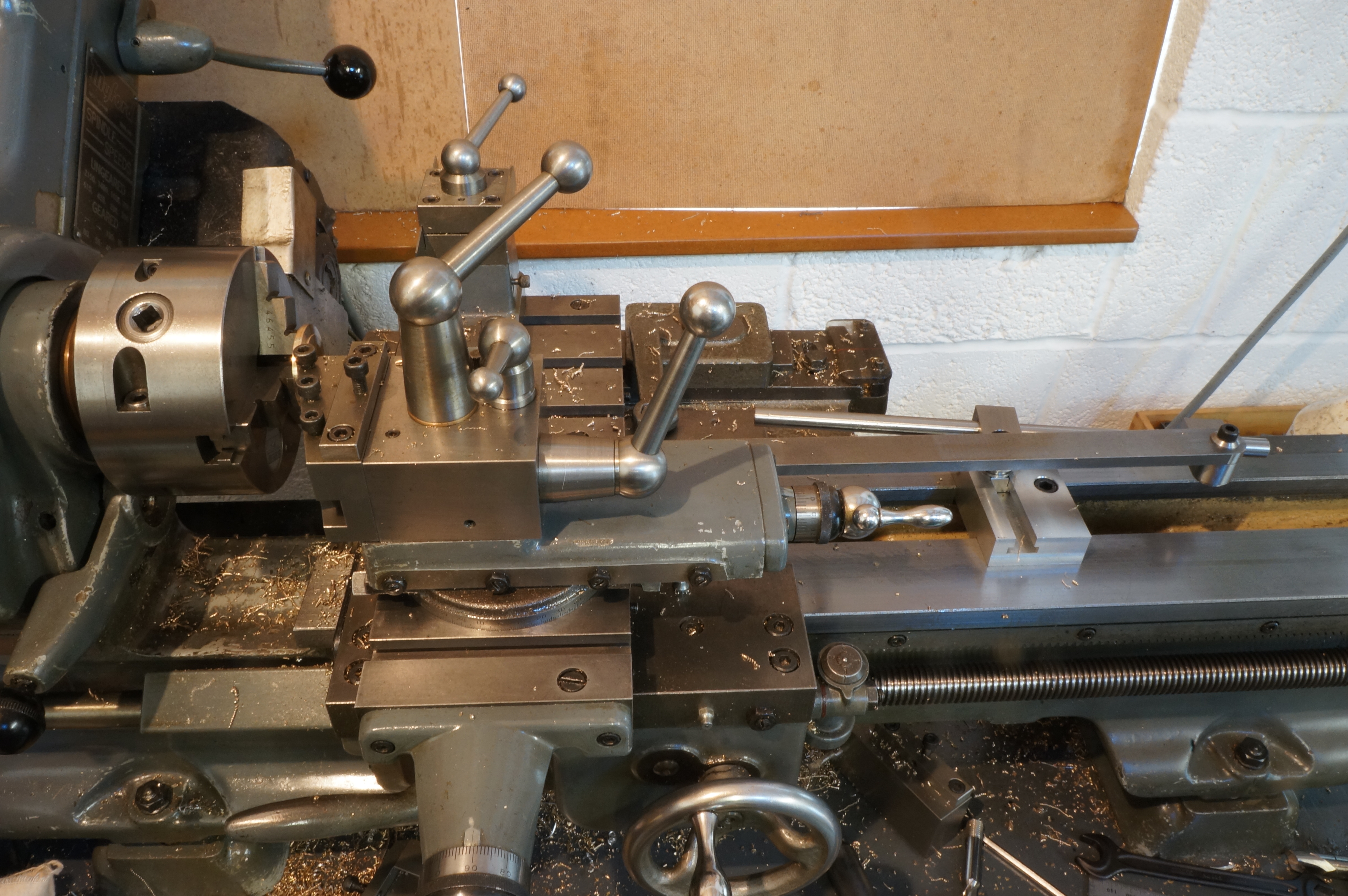
If I remember rightly I had to use a telephoto lens to get the depth of field for this photo. It was stopped right down using aperture priority and a long auto exposure, tripod, and a remote shutter 'zapper', as I usually do with these workshop shots. I think it has come out pretty well. (2¼ hours)
2017-11-18 – Making another Filler Cap
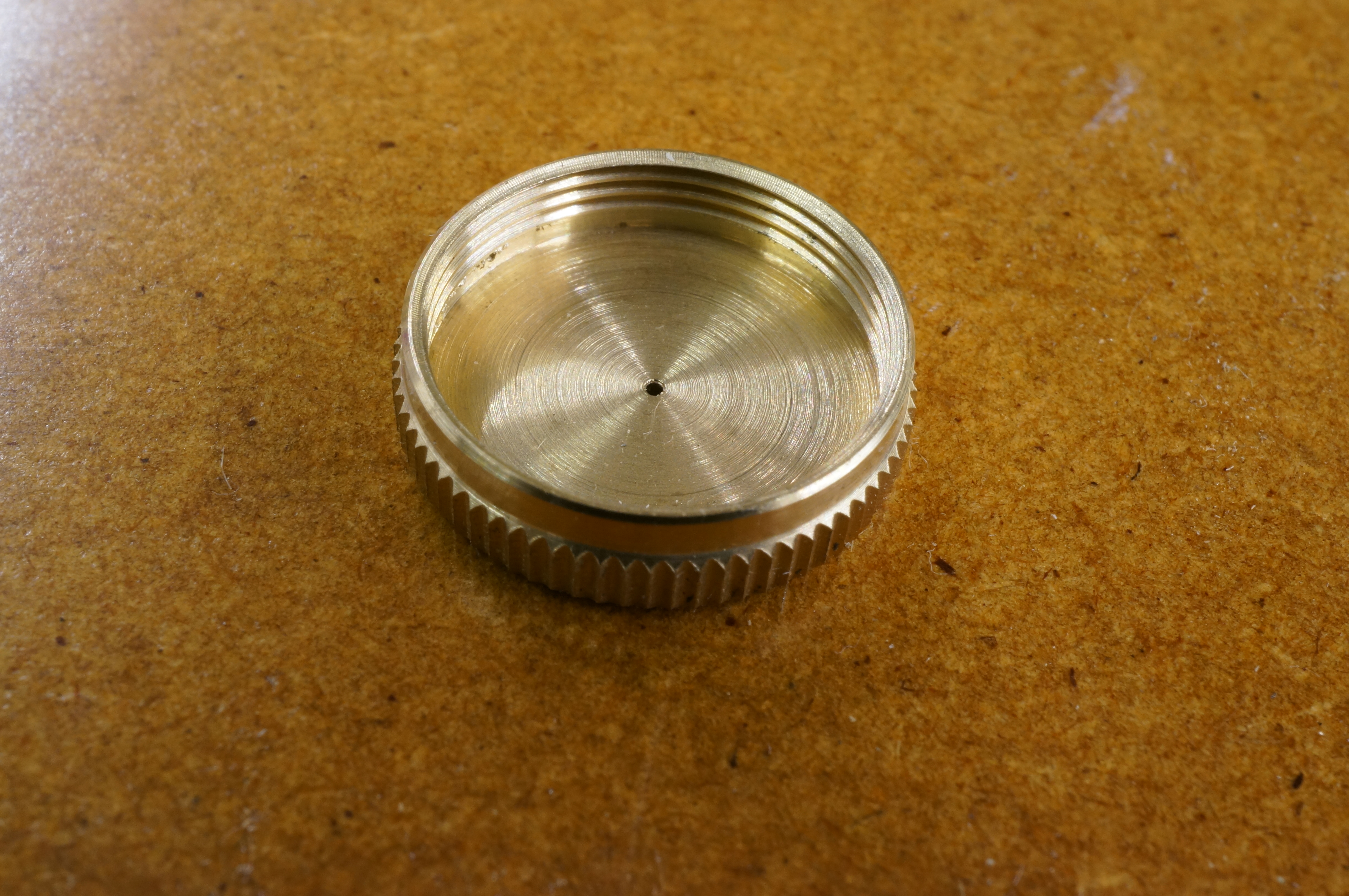
After finishing a small internal threading tool bit, I made another filler cap today. This time it fits nicely. I also started work on a filter to fit in the filler neck. I turned a collar and roughly cut out a rectangle of fine brass gauze. (4¾ hours)
.
2017-11-25 – Not making a filter (or anything else)
I made an aluminium former for the cylindrical filter gaze, and a ring and plunger for pressing a flanged end. I tried soldering the cylinder, but could not get enough flux to the job. I then remembered I had flux paste - try it on the next one. I cut some more gauze and pressed a cap piece, trimming it while still held in the ring die. I tried a shorter piece for the cylinder to minimise the overlap, but it seems 15⁄16″ is too short.
As an experiment for making the 'angle iron' engine stand I cut a piece of the 3⁄8″ × 1⁄16″ brass angle and filed a 90° V notch cutting away one leg and half the thickness of the other. Bending it to a right angle went well, up to the half way point, when it snapped. I will need a mitre soldering jig, it seems. (4½ hours)
2017-12-02 – Making a filter
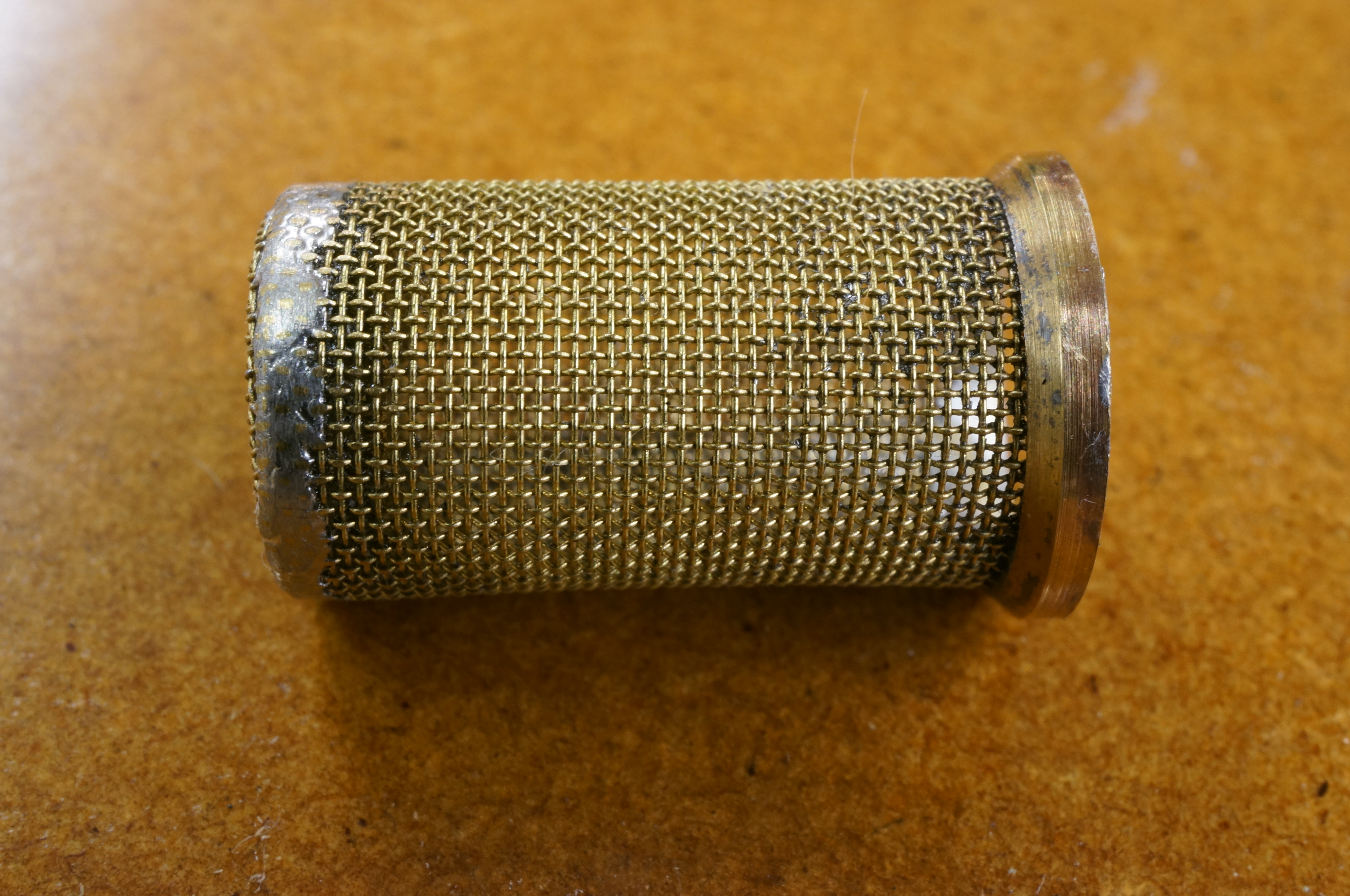
A third try at a piece of gauze for the filter turned out the right size. I fitted it in the sleeve and soldered the end cap in, and half way up th side seam. After filing the joint to fit in the sleeve with the top end projecting, I was finally able to get enough heat into the job to solder the the collar round the top. I used files and a fine point in the Dremel to remove the excess solder, and finished with 400 grit paper with the filter held delicately in the 3-jaw chuck. (1¼ hours);
.
2018-01-20 – Boring filler hole
After working on the engine stand this morning, I moved back to the tank, setting up the drum in the milling machine for the filler and outlet holes. The outlet hole was drilled and reamed, and the filler hole counterbored to form a ledge for soldering the filler neck in place. I also turned up a protective cap to shield the filler threads from the soldering torch flame. (2¾ hours)
.
2018-02-03 – Soldering
I drilled vent holes in the shield cap and made up a long stud to hold the filler and outlet boss in place during soldering. I carefully completed the preparation for silver soldering. On soldering, I more or less completely failed to make most of the joints properly. The outlet bush was OK. This one is a scrapper. Later saw it in half to try to learn from it. One conclusion is that these days I can't get eye or hand close enough to the job to see it well enough to feed fine solder rod steadily enough. (1¾ hours)
2020-04-05 – Starting another tank
The remaining brass tube from the first tank was oval as supplied so I have ordered some more. Meanwhile I sawed out two more squares of 3⁄16″ thick brass for the ends, and made the outlet bush and the filler neck, which I nearly parted off before it was complete. (2½ hours)
2020-04-11 – Cutting the tube
Using a cutting disc in the Dremel, I chopped a length of the new brass tube. With some light alloy from the scrap box I made up a pair of bungs for turning the ends of the tube. While set up, I also turned the ends of the remaining length of tube.
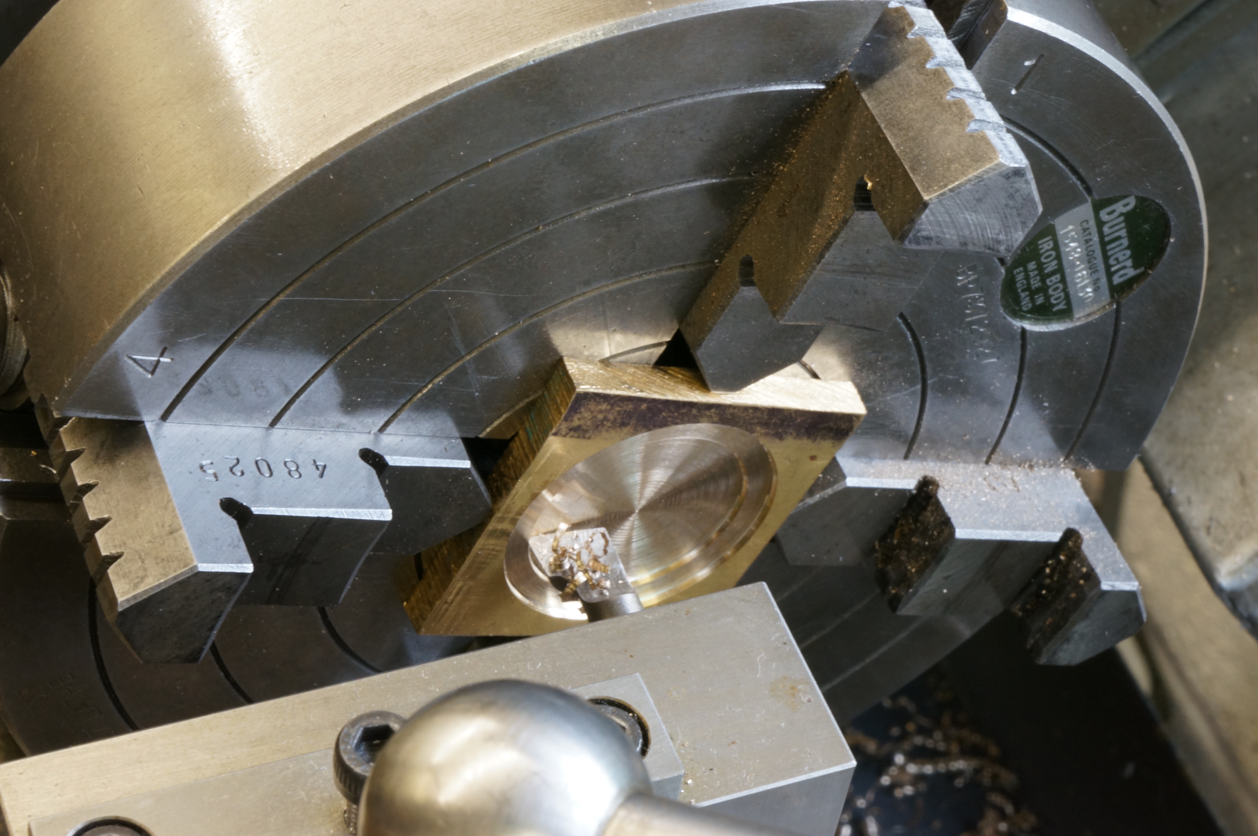
Next, I set up one of the square end plate blanks in the 4-jaw, getting the face pretty true using the end of the tailstock barrel to push it into the chuck jaws before final tightening. I turned the accessible OD to 1.470′ for a length of 0.075″ and then made the spigot to fit inside the tube to 1.413″ for 0.045″. Either end of the tube fits nicely.
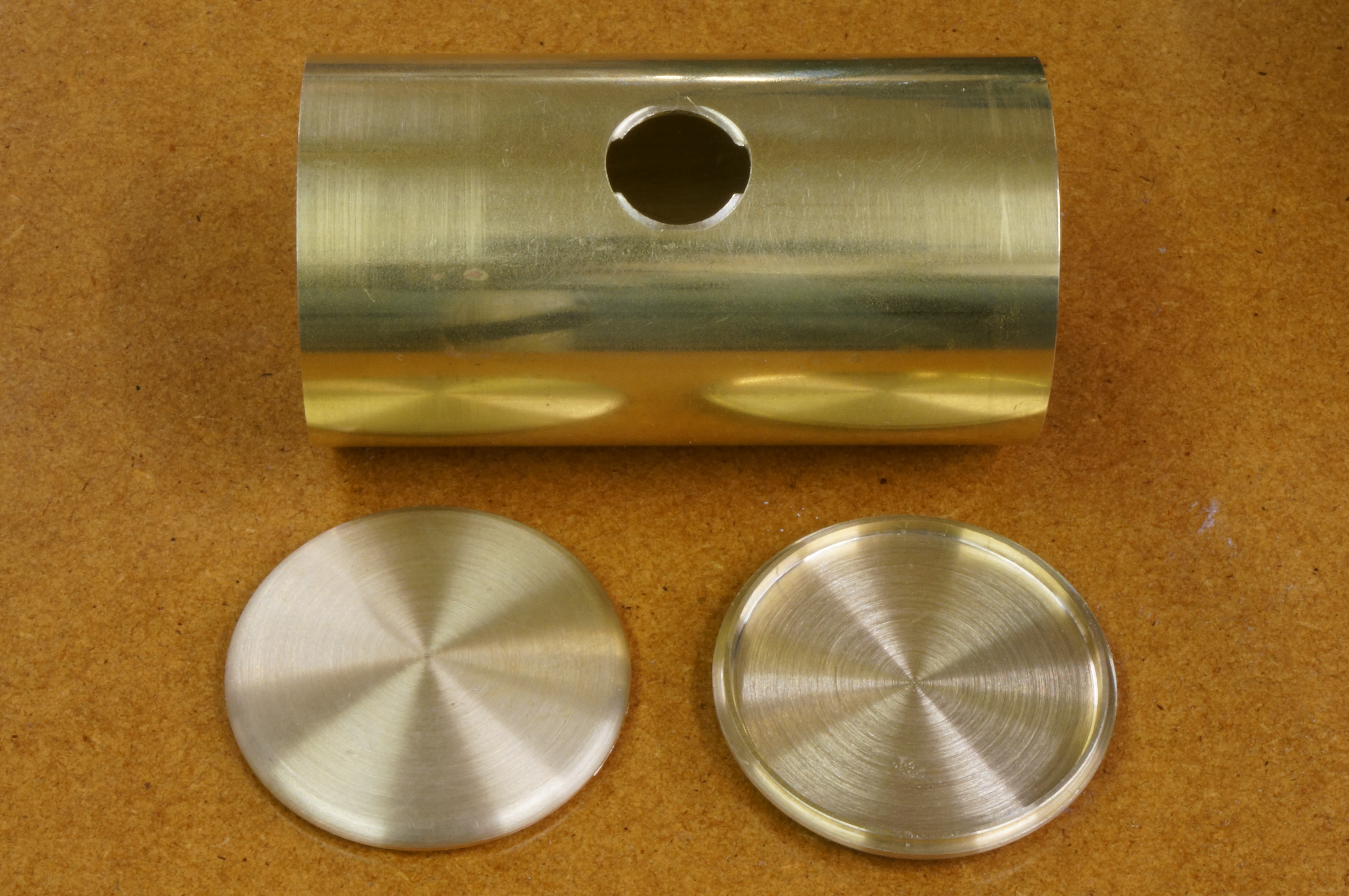
2020-04-13 – Doming the end caps

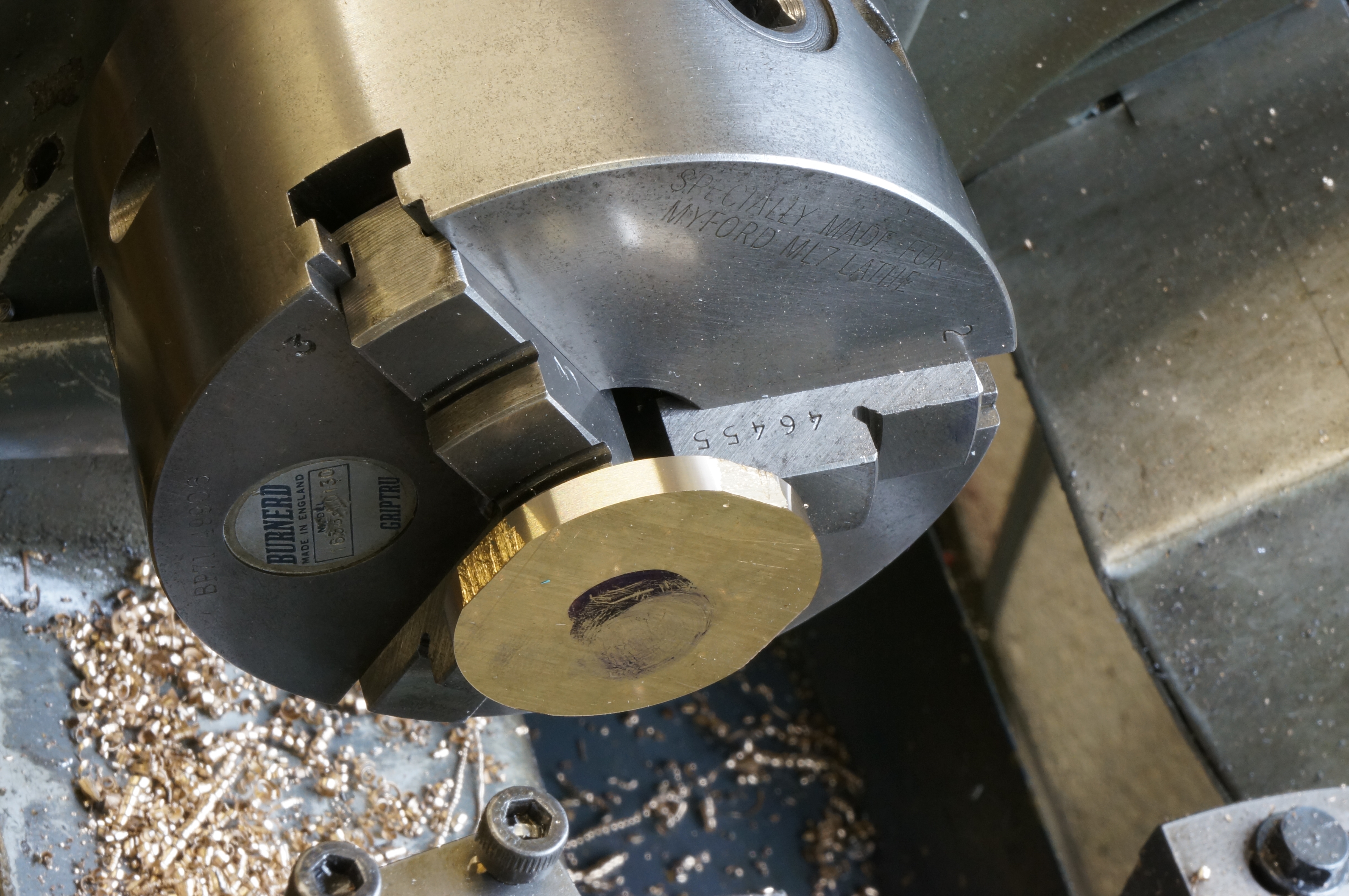
I bored the internal recess on the end cap which left the shoulder now slightly over size, and then repeated the operations on the second piece but bored it out before turning the shoulder. I turned the 4″ 'dish' radius on the outside faces of both caps, again using my large radius turning accessory. One blank I turned to final OD. (2¾ hours)
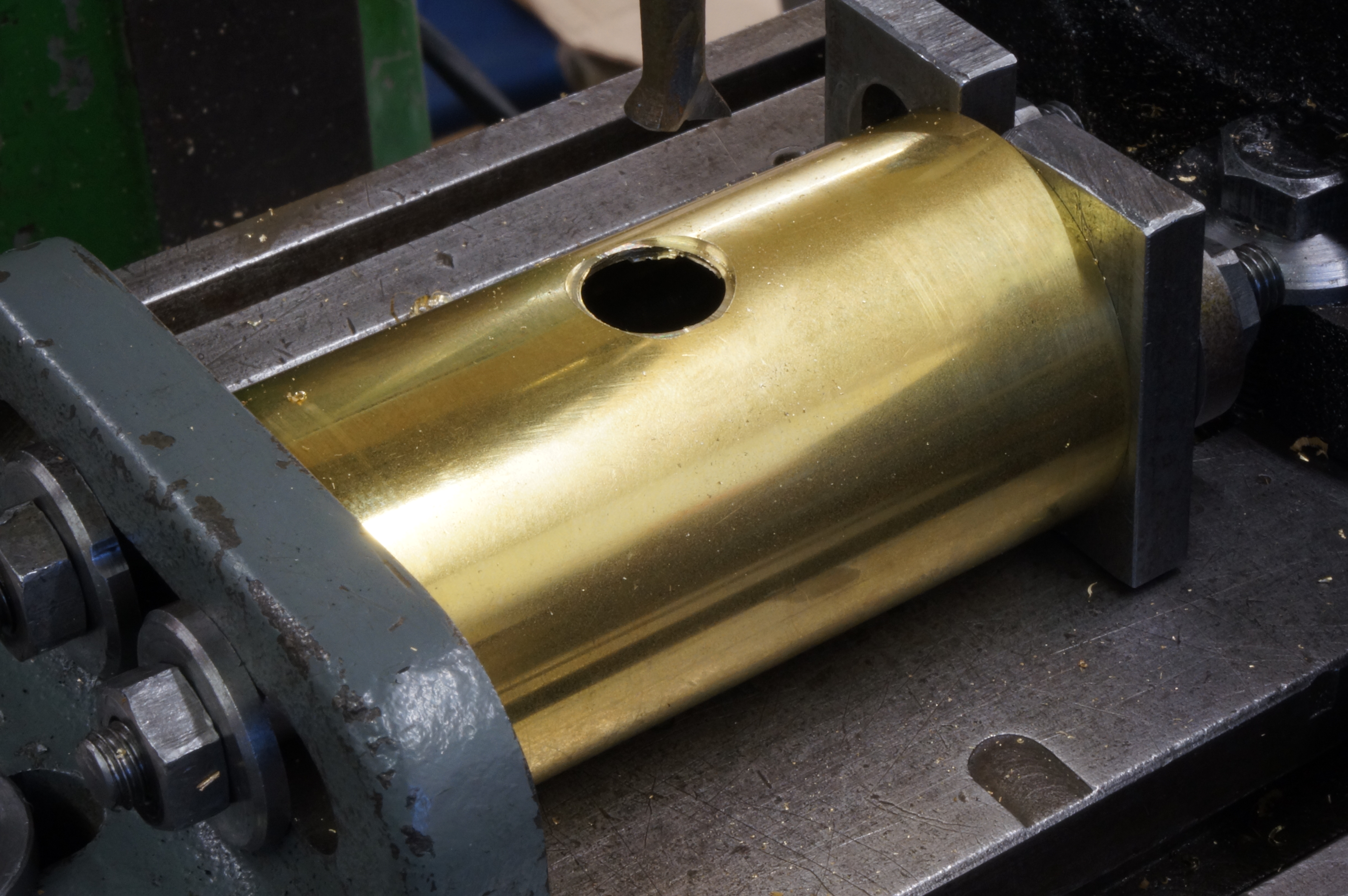
2020-04-17 – Drilling the tube
Today I finished the end caps with a corner radius, cutting three chamfers and blending with files and fine grit paper. As usual, in the later stages I took off more than would have been ideal. I need to make more form tools for small radii.
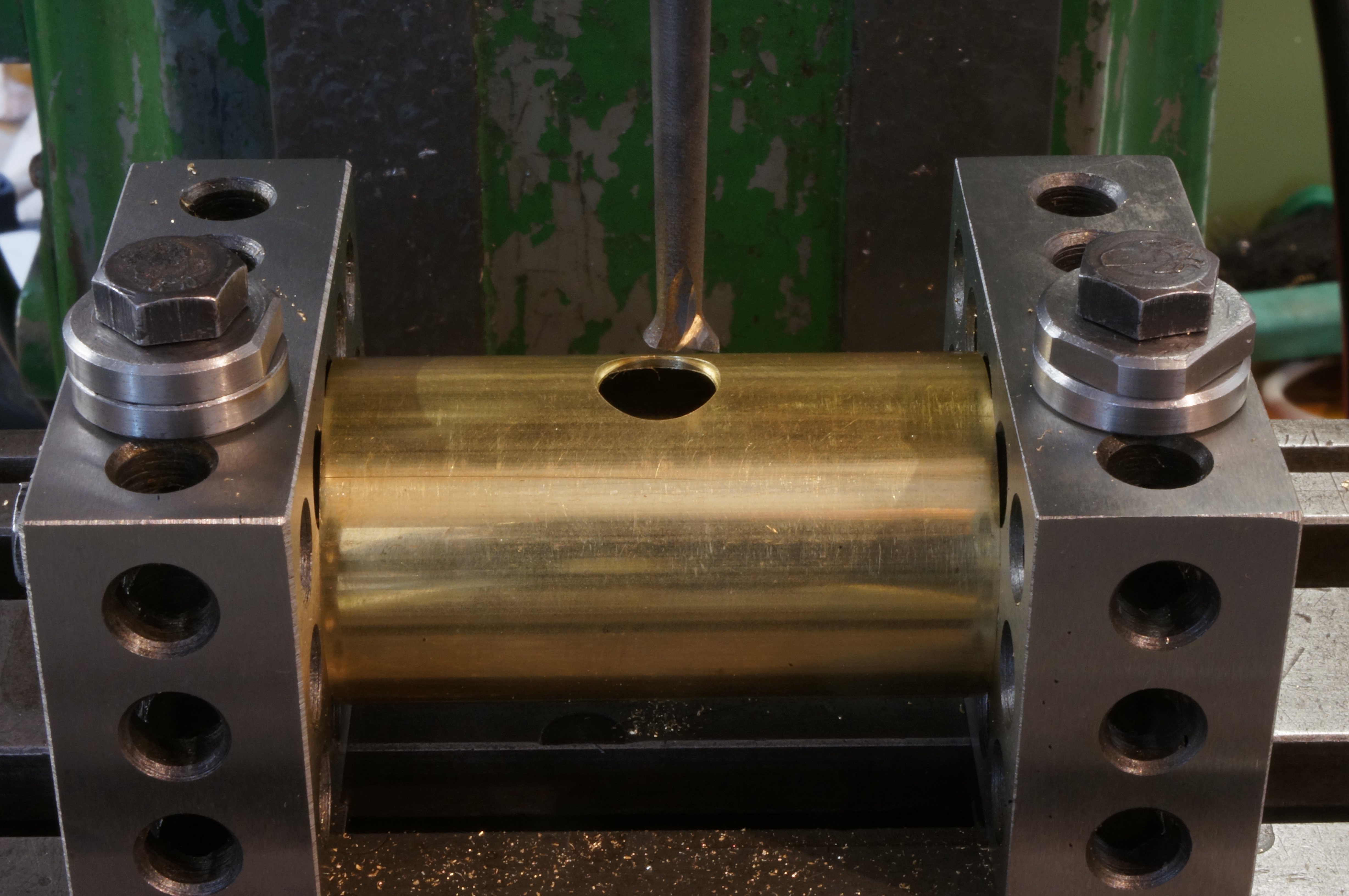
I spent quite some time faffing about trying to think of a way to set the tube up for making the filler and outlet holes. The problem being that I wanted the holes diametrically opposite, ideally without marking and measuring. Eventually, poking about in a tooling drawer, I came across the pair of 1,2,3 blocks I had recently bought (with no particular expectation of ever finding much use for them). With the tube clamped between the blocks by a through bolt, I could drill the outlet hole and then turn the whole caboodle over to bore the stepped hole for the filler.
After deburring the tank barrel, I made up a pair of bronze pieces for a fuel tap body, to be silver soldered in the form of a T-piece. After turning, I milled a recess radially in the cross-bar for the leg to fit into, but had some difficulty getting a good fit. (5¼ hours)
2020-04-18 – Soldering
The fuel tap pieces are not good enough for a finished item, but will do to try out some new silver solder and flux. At the first attempt with these little parts I found I simply could not hold the 0.7mm silver solder steadily enough to apply it to the heated joint. With some difficulty I dismantled the parts and cleaned them up again, re-fluxed and reassembled. With a little piece of solder pre-placed on the joint, the second try was much better. I am not sure this is the right was to make a tee. Making the side piece as a saddle would be more difficult to hold in place for soldering but might produce a better looking joint.
In the afternoon I soldered the filler neck and outlet boss into the tank tube. I held them in place as with the first tank, but used pre-placed solder pieces. That went well enough, and after cleaning up, I soldered both tank ends in place, again with pre-placed rings of solder. After pickling and cleaning I started filing away the excess solder round the ends of the barrel. There is still more finishing work to do. (4¾ hours)
2020-05-09 – Bending the tank saddles
After doing a little more work on the radiator stand, I cut out a piece of 20 gauge (0.9mm) brass sheet for the tank feet. I filed a radius on one edge of a strip of aluminium to make a former for bending the sheet to an angle, annealed the brass sheet and bashed it inexpertly over the former to a right angle. After filing and sanding away the lack of skill and patience, I milled the edges to give me a length of 1⁄4 × 3⁄8″ angle. This was done with cuts of just 0.030″ and climb milling the edges. Next, I sawed the angle in half, and milled across one end of both pieces. (3½ hours)
2020-05-10 – Cutting pieces for the tank stand
First, I milled the other ends of the tank saddles to length, drilled the mounting holes, and milled bevels at the ends of the vertical legs of the angle.
Later, I cut eight pieces of brass angle (and a spare) for the tank stand, which is similar to the engine stand but smaller. (2 hours)
2020-05-10 – Milling pieces for the tank stand
I milled the top sections of the stand to length and for mitre joints, and cut the mitres on the legs, which will be finished to length after soldering. I then cut down the corner soldering jig (previously made for the engine stand) to cater for these smaller parts. (2 hours)
2020-05-16 – Making the first joints
This afternoon I soldered the first two mitred joints in the tank stand angles. They pieces are accurately square, but there is a slight misalignment on the flat face. I cut the soldering jig down further to allow the final joints to be made, but I cannot get the parts properly set. (1¾ hours)
2020-05-17 – Shaping the saddles

I am not sure the jig is good enough. I may have to re-think it. I am also not sure the joints soldered yesterday will pass inspection.
After a bit of general tooling improvement work, I drilled and tapped holes in a mounting block for the tank saddles. I used a boring head to cut the tank seating arcs on the saddles, a job that was prolonged by an infuriating half-hour search for the 'very-near' calipers, which were hiding in plain sight, somewhere unexpected, again. Good thing I found them, as the saddles were much closer to finished size than I thought.
The last job today was to cut out a piece of aluminium sheet to make a jig for soldering the saddles to the tank. (3½ hours).
2020-05-20 – Soft soldering the saddles
I milled the jig to size and drilled and tapped the holes in the corners, then made up a threaded plug to hold the jig and saddles in place, using the tank outlet hole for location. After soldering, I made a start on cleaning up the joints. (3¼ hours)
2020-05-22 – Experimenting with extrusions
After some more filing and rubbing the soldered saddle joints, I looked into the feet for the tank stand. I decided to make them longer than I had drawn to give more spanner clearance for holding down bolts. After cutting the brass angle to 211⁄16″ long, I heated them to red and measured again. They had shrunk by 0.010″ on length, confirming my suspicion that brass extrusions do shrink axially when silver soldering. (1¾ hours)
2020-05-23 – Cutting new tank stand pieces
With a couple of other little jobs done, I cut up some more brass angle for another go at the tank stand. I think I must have thrown out an aluminium 45° setting gauge, having forgotten its purpose, so I had to make another before cutting the mitres. I heated the new top pieces to pre-shrink them, and cut the mitre at the top of each leg. Turns out one of the new top pieces and melted a bit. I have no more angle stock, but I was able to slavage a long enough piece from one of the mis-soldered legs. (1¾ hours)
2020-05-28 – Mitring tank stand pieces
I cut the mitres on the new tank stand top pieces, and while set up, cut the bevels on the feet. An examination of the soldering jig shows it is distorted. I think a new one is called for. (1½ hours)
.
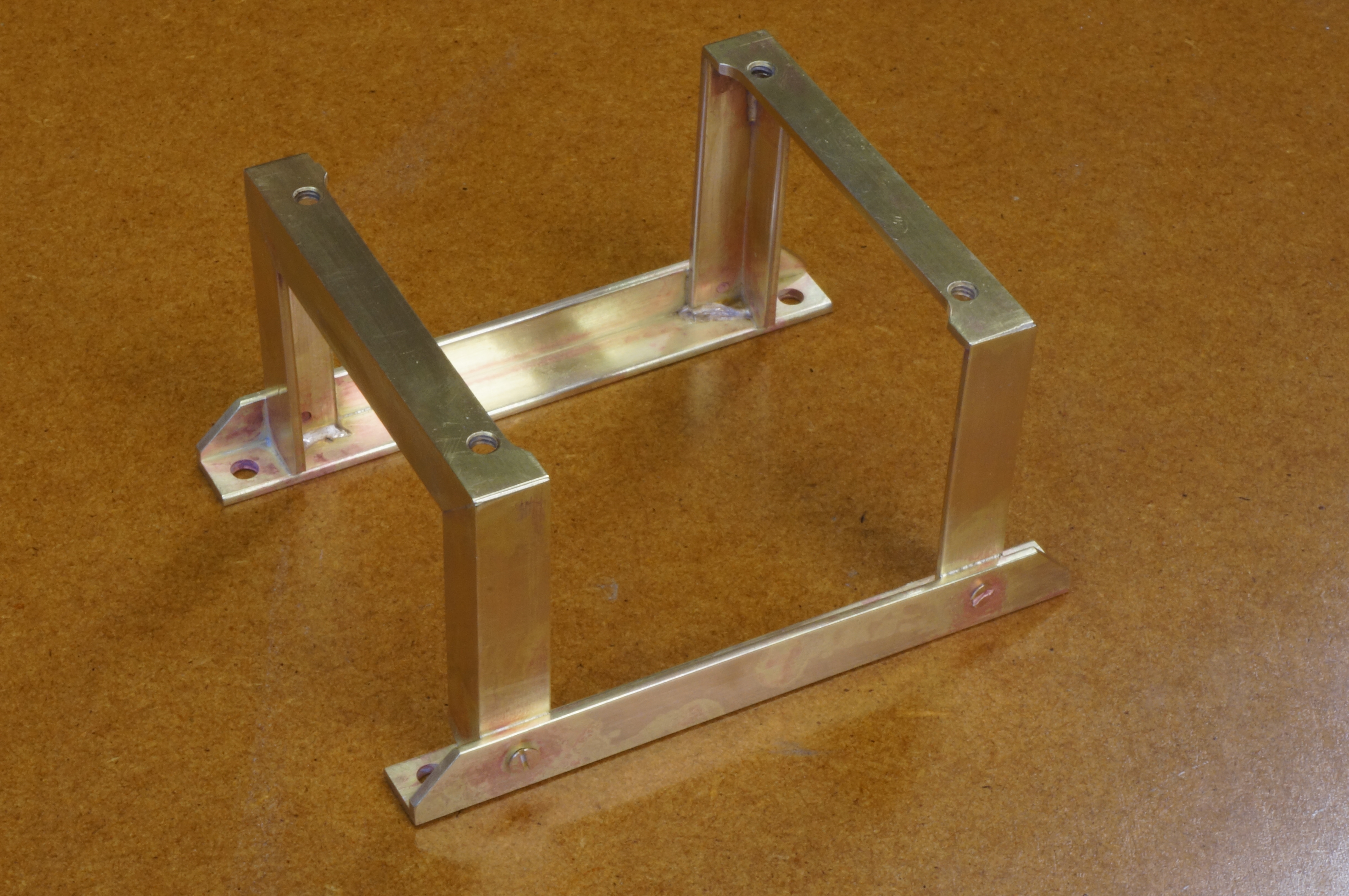
Engine Stand
2017-12-09 – Making a mitre setting gauge
I have been given some unwanted architectural colour samples of anodised aluminium. These are going to come in very handy for jigs, sacrificial mounting plates, and the like. I turned one of them into a setting gauge for milling mitres on the brass angle for the stand. Having cut up the brass angle pieces for the stand, I milled some of them to length and cut a couple of bevels. (2 hours)
2017-12-23 – Milling bevels
I milled the remaining 10 bevels. The angles are slightly off, and will need a little filing to to get a neat joint. Next, I started work on a jig to hold the mitres for silver soldering. I sawed out a plate and milled the edges square, and made a square cut-out in one corner where the pieces will meet. The piece was made from the edge of some black steel plate, and it needed a little flattening. The last job on the plate was to mark out, drill, and tap holes for the clamp screws. (3½ hours);
2017-12-26 – Making clamping dogs
After making the clamping dogs to finish the jig, I silver soldered the first joint. This was pretty good, apart from some bruising of the soft brass by the clamps, and some excess solder inside the joint. For the second joint I pre-placed a piece of solder on the joint. I then dropped it on the floor in the way to the quench, bending the leg and breaking the joint. (1½ hours [est]);
2017-12-27 – Soldering first joints
I chopped the damaged end of the top piece to make a new leg, and cut a new top piece. After improving the squareness of the jig, I soldered the joint using a pre-placed piece of silver solder about 1⁄8″ long. Next, I soldered the remaining two joints to complete the second arch. For the final one, I dropped the size of the propane burner, but it proved harder to get the joint to take, needing extra solder and a scratching rod. (2¾ hours)
2017-12-30 – Cutting legs
The two stand arches were soldered with the legs slightly over length, to allow them to be milled to an accurate size before the next step. With these milled, the next job was to cut away the top angle slightly, on the top face, to clear the bolting lugs on the engine sump.
I played with a scrap piece to examine filling the inside corner of the brass angle to more closely resemble rolled steel angle. It looks better, but probably not enough to justify the considerable work.
I drilled and tapped the engine mounting holes in the angles, and the assembly screw holes in the feet, and in one leg. (4 hours)
2018-01-06 – Finishing the assembly
After drilling a tapping the remaining holes in the legs, I made up a plate jig to hold everything square for soldering. I needed to file the bottoms of the legs a little and open some of the holes in the feet to ensure the both sit flat. I filed a radius on the inside edges of all the pieces, this again makes them appear more like rolled angle, and is much easier than a fillet at the root. Checking with the engine, I found I needed to file a small relief to clear the timing case. I silver soldered one foot at a time, using pre-placed solder pieces about 3⁄8″ long. After soldering, I pickled it and cleaned it up. Most joints good, one left with a bead of solder. (5 hours)
.
2018-01-13 – Filing, blasting and priming
For reasons I don't understand, the arches have ended up noticeably splayed apart at the top (or rather, pinched at the bottom). I filed the heads off the screws and removed excess solder with the Dremel, then bead blasted, scrubbed in hot soapy water, rinsed, dried, and can-sprayed a couple of coats of grey primer. (3⅓ hours)
2018-01-20 – Filling
The mitre joints and some bruising needed a bit of filler, for which I used knifing putty. (1 hour).
2018-02-03 – Rubbing down and painting
I rubbed down the filler, and washed and primed the stand again. Later, I sprayed a coat of gloss black. (¾ hour)
.
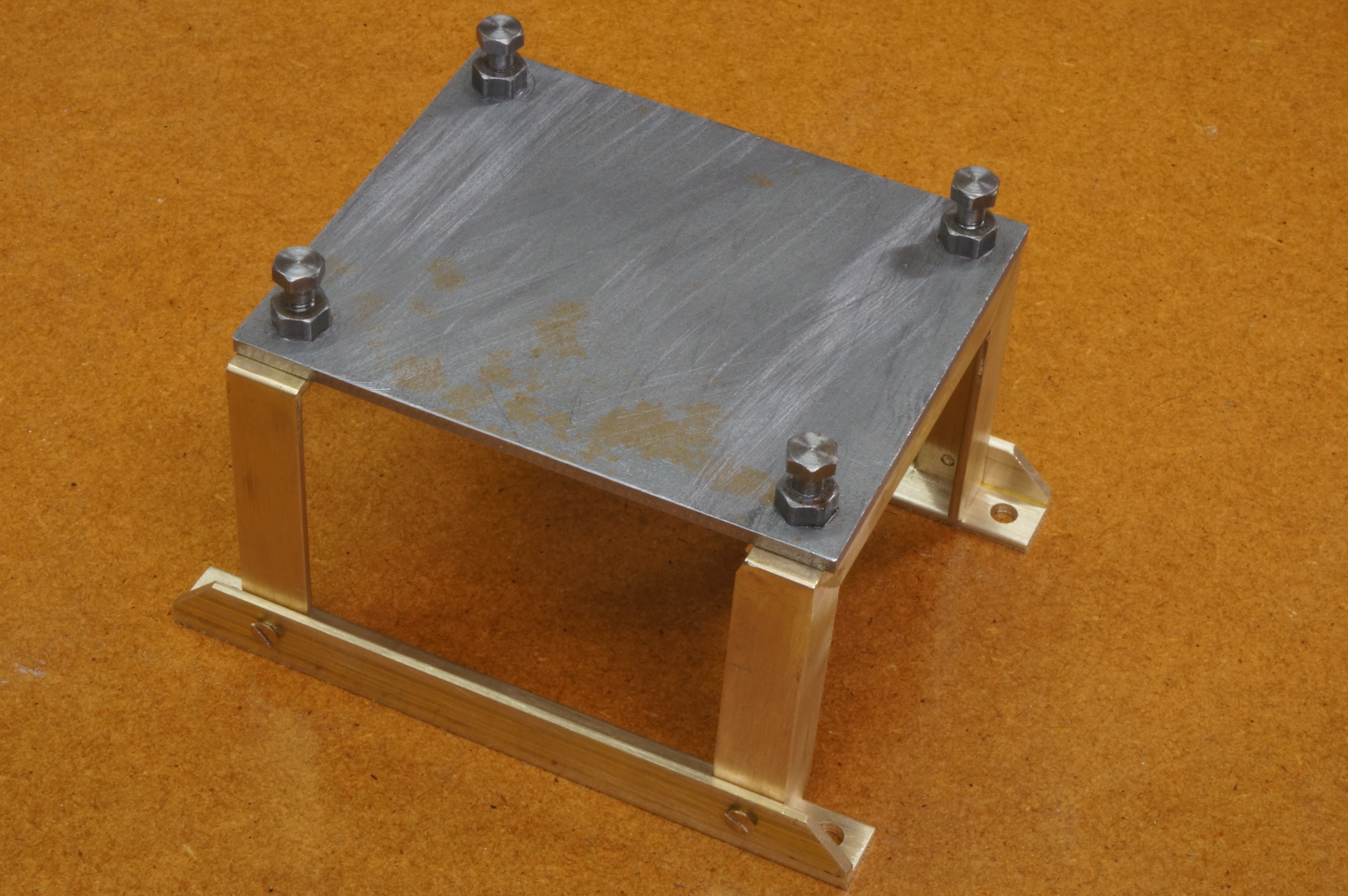
Radiator Stand
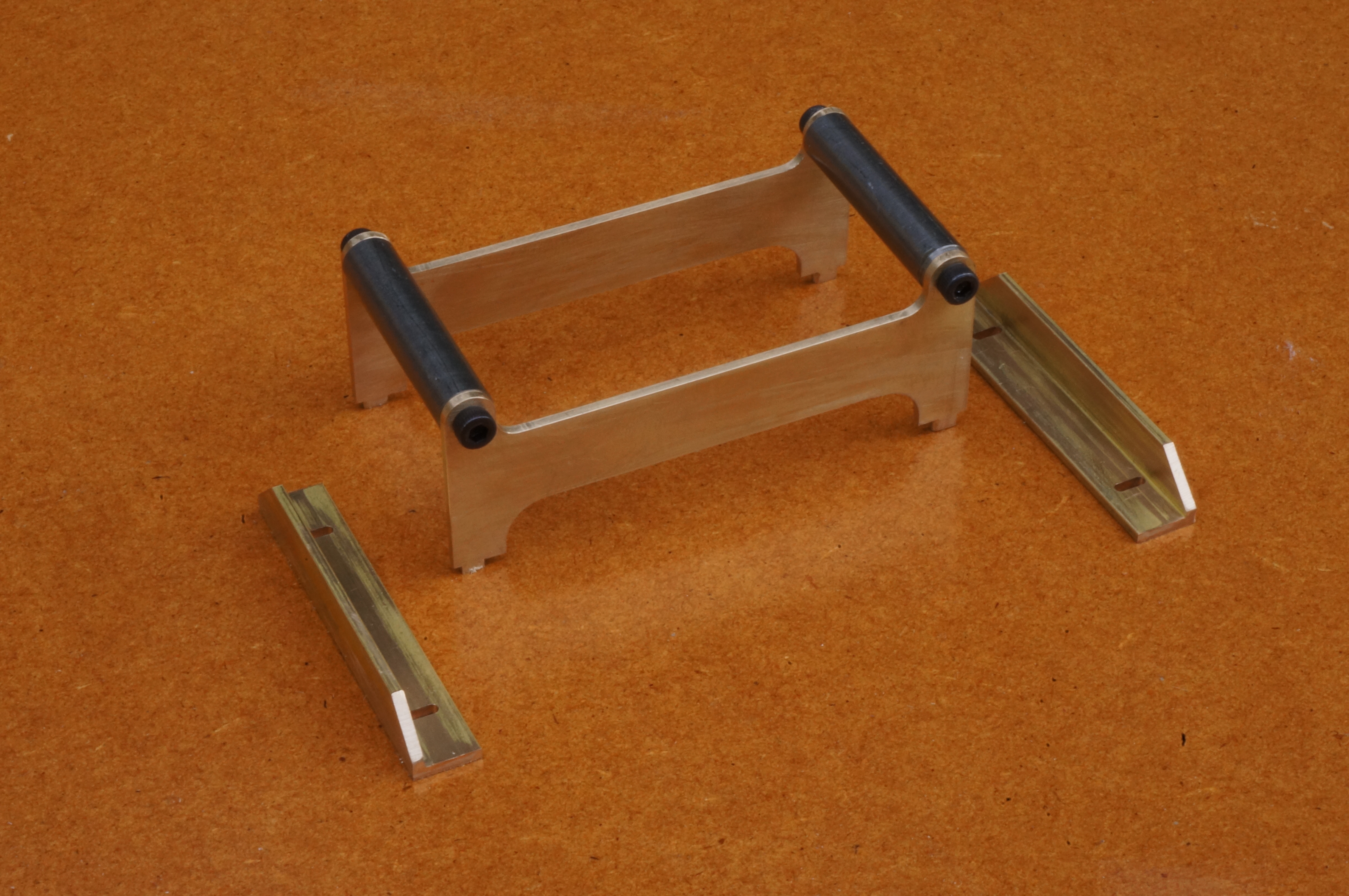
2020-04-25 – Annealing the feet
I cut two pieces of ¼ × ¼ × 1⁄16″ brass angle over length and milled the ends square, then annealed them for axial shrinkage, of which there was enough to make a difference. After cleaning them up I milled them to their final 2¼″ length. Next, I cut rectangles of 1⁄16″ brass sheet for the side plates, and milled the edges. For this assembly I am trying out tab and slot (or mortice and tenon) location for the parts. The final job today was setting up the angles for milling the slots. (2¼ hours)
2020-04-27 – Slotting the feet
Today I milled the tab slots in the feet, and milled the bevelled ends. I made the bevels a shade bigger than the intended ¼″, but as there is no dimension on the drawing it doesn't matter! (1¾ hours)
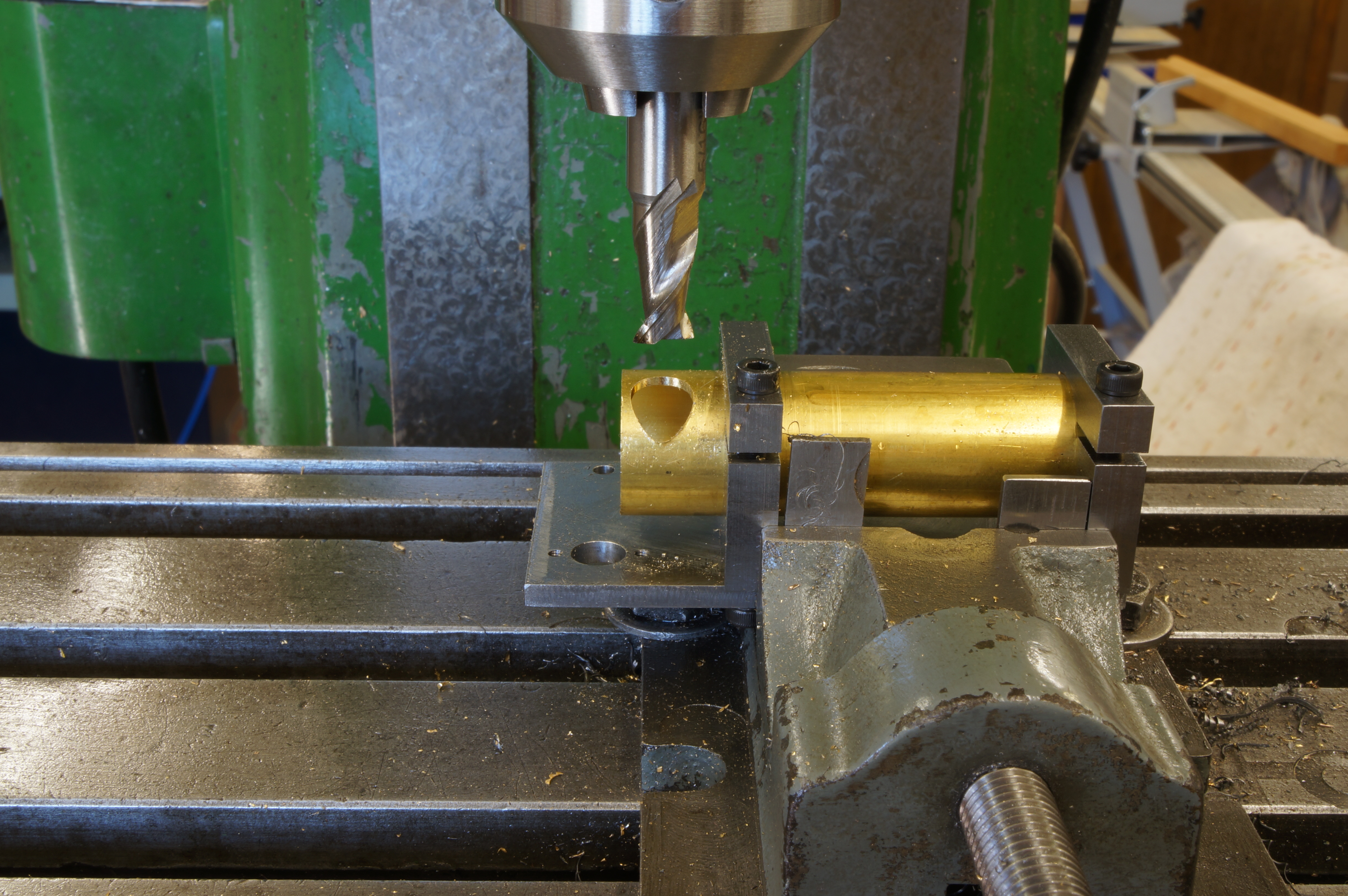
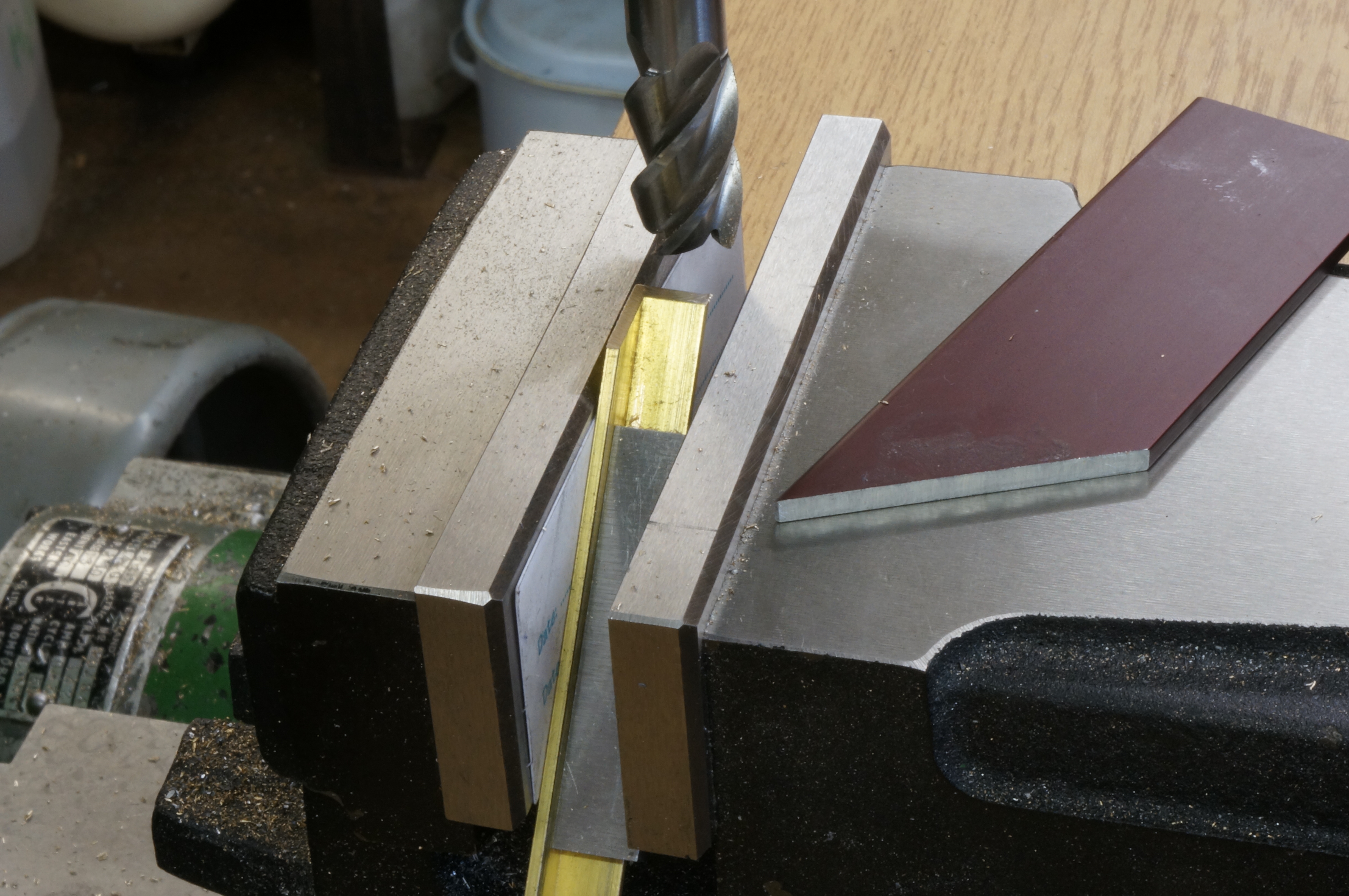
2020-04-28 – Milling tabs

Today I milled the locating tabs on the plates. While filing radii on the tabs to fit in the milled slots, I realised I had not set the edge of the plate level and the tabs were longer one side than the other. This may be recoverable by making the stand a little lower than intended and reducing the size of the radiator mounting lugs. I milled the sides square to the new base line, losing 0.017″ on the width. After finishing the tabs to fit, I decided, eventually, on dropping the radiator mounting holes by 1⁄64″.
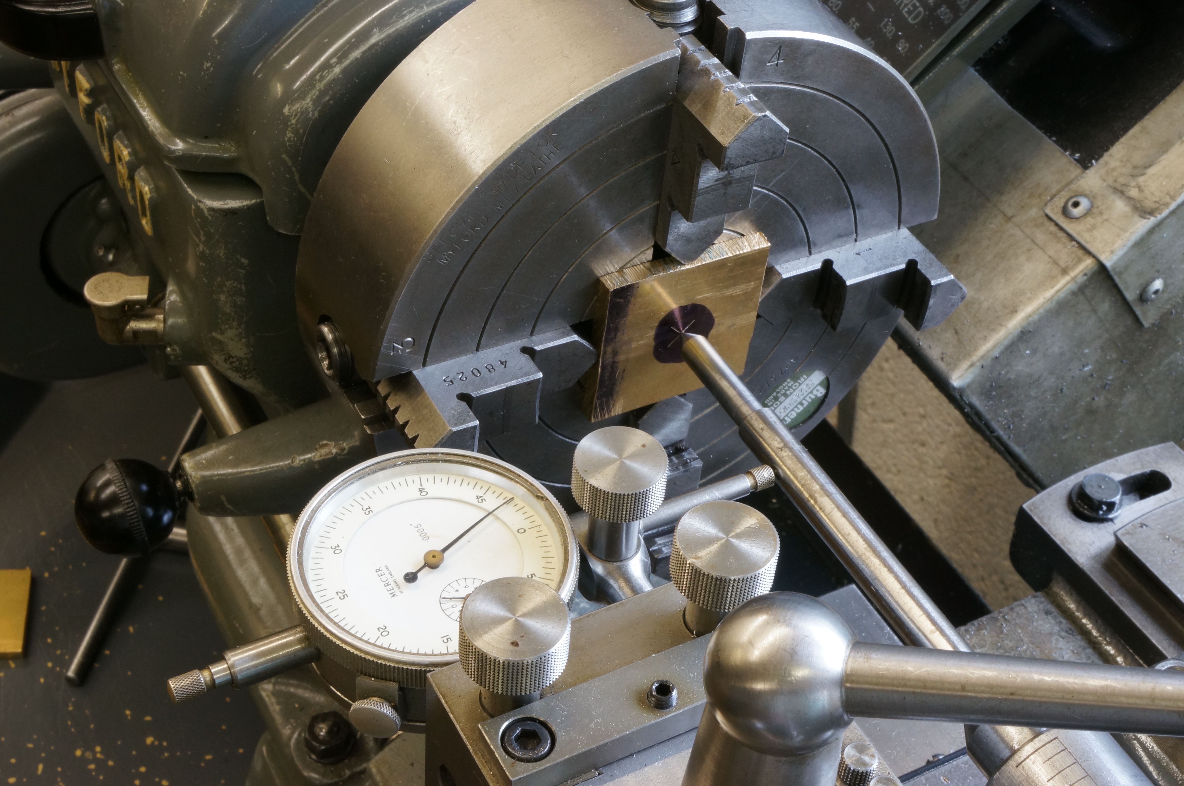
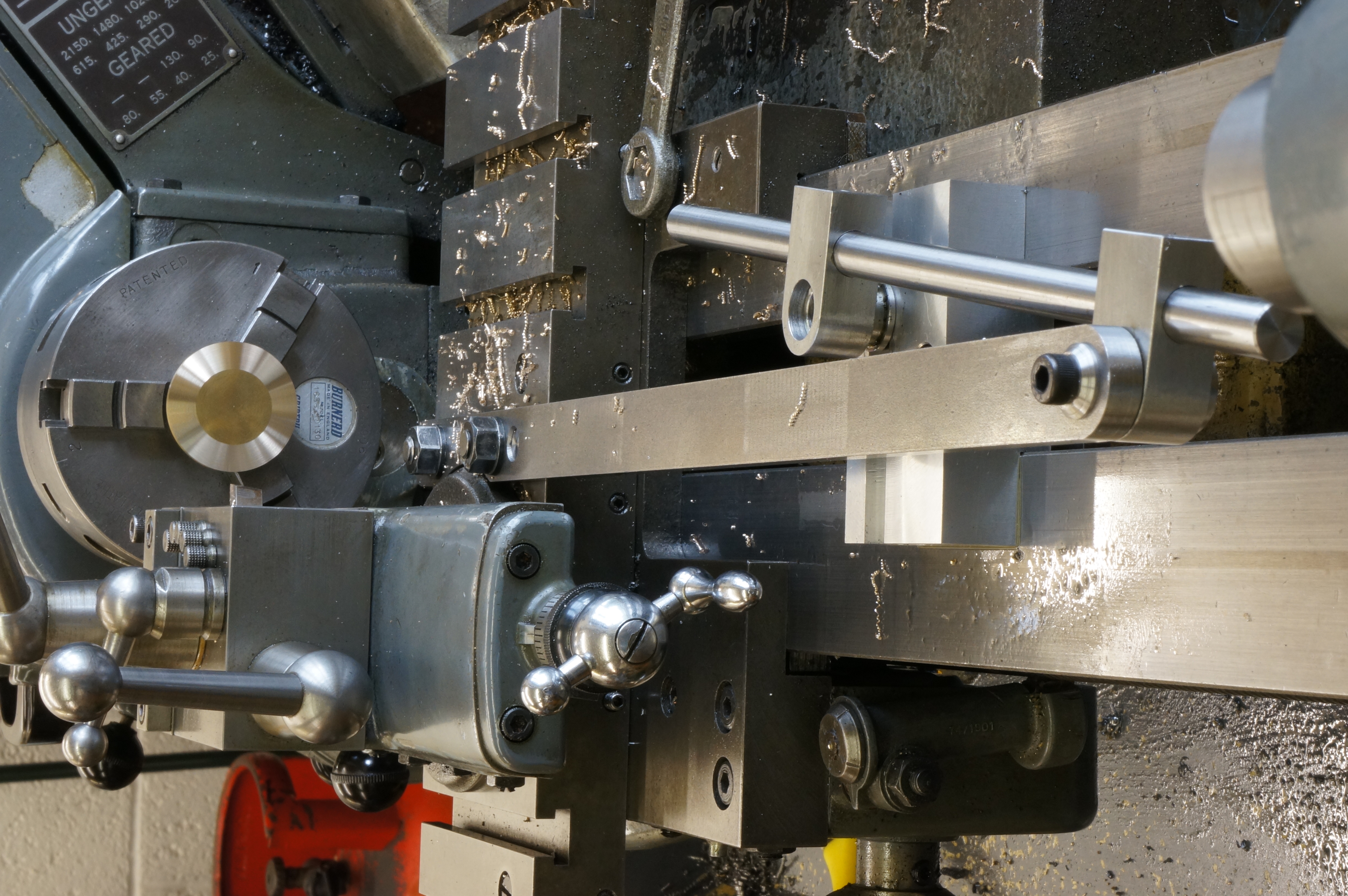
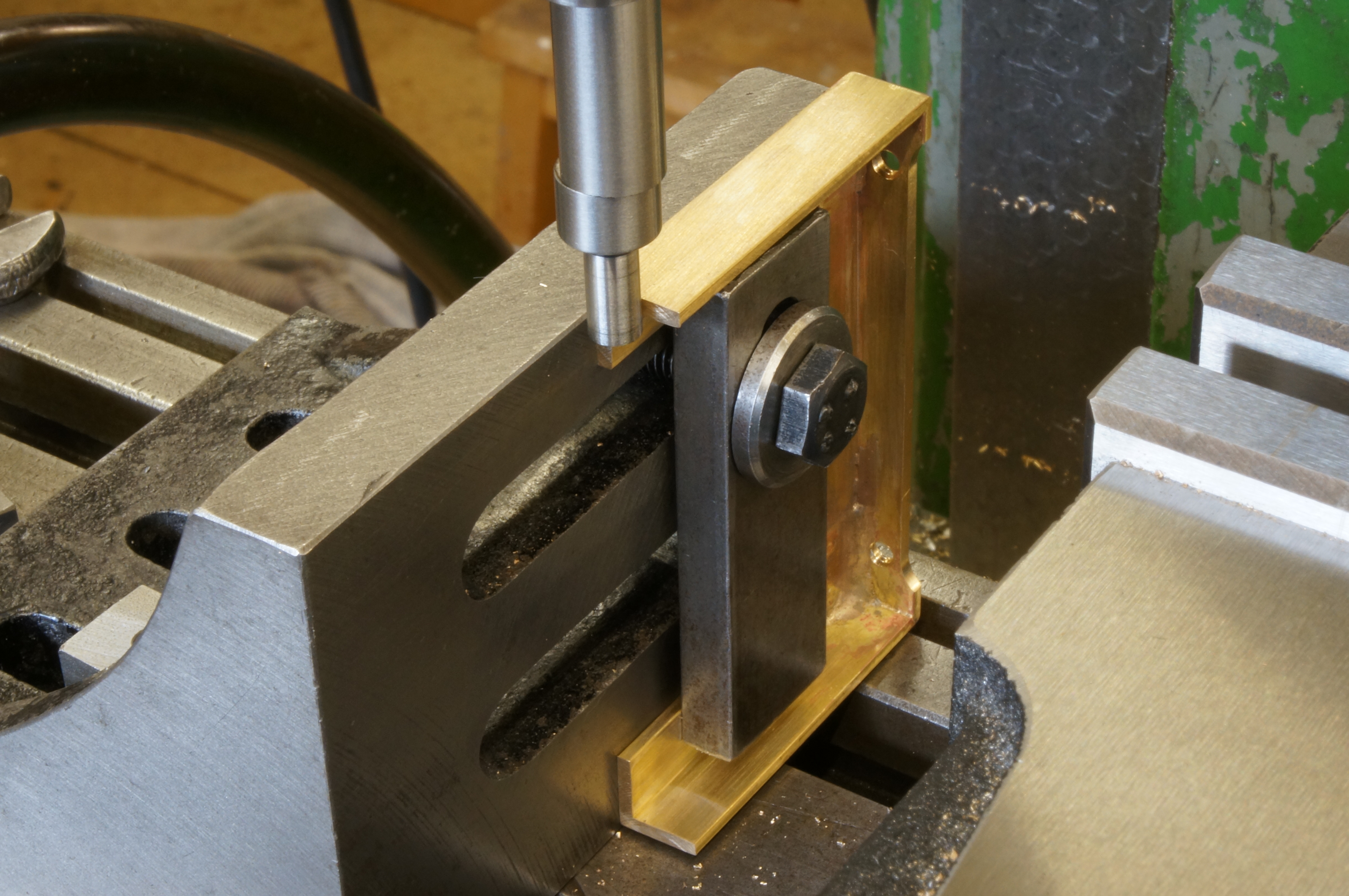
Next, I made up an aluminium jig plate for milling the profiles of the plates. With the plates mounted on the jig, I took a trueing cut along the top edge and milled the top cut-out with a ¼″ long series slot drill. At one point the cutter worked loose, but no damage done and milling the 'ears' completed. On a trial assembly I needed to ease the holes on one side to allow the bolt heads to pull up. (The above photo of the milling setup was staged after the plates were finished). (5¾ hours)
2020-04-30 – Finishing the side plates
I should not have opened the holes yet, because it made setting back up for milling the bottom cut-out more difficult. Also, with the plates held only by the screws in the lugs, the milling forces have lifted the plates in the middle, putting a slight bend in the plates. The cut-out was milled with a slightly undersize cutter, but no-one will know.
With the machining finished, I made up a couple of filing buttons, dropped one inaccessibly, and made another. I filed the ears to shape and sanded all the milled edges. Finally, I made a pair of spacers bars to hold the plates for soldering. (3¼ hours)
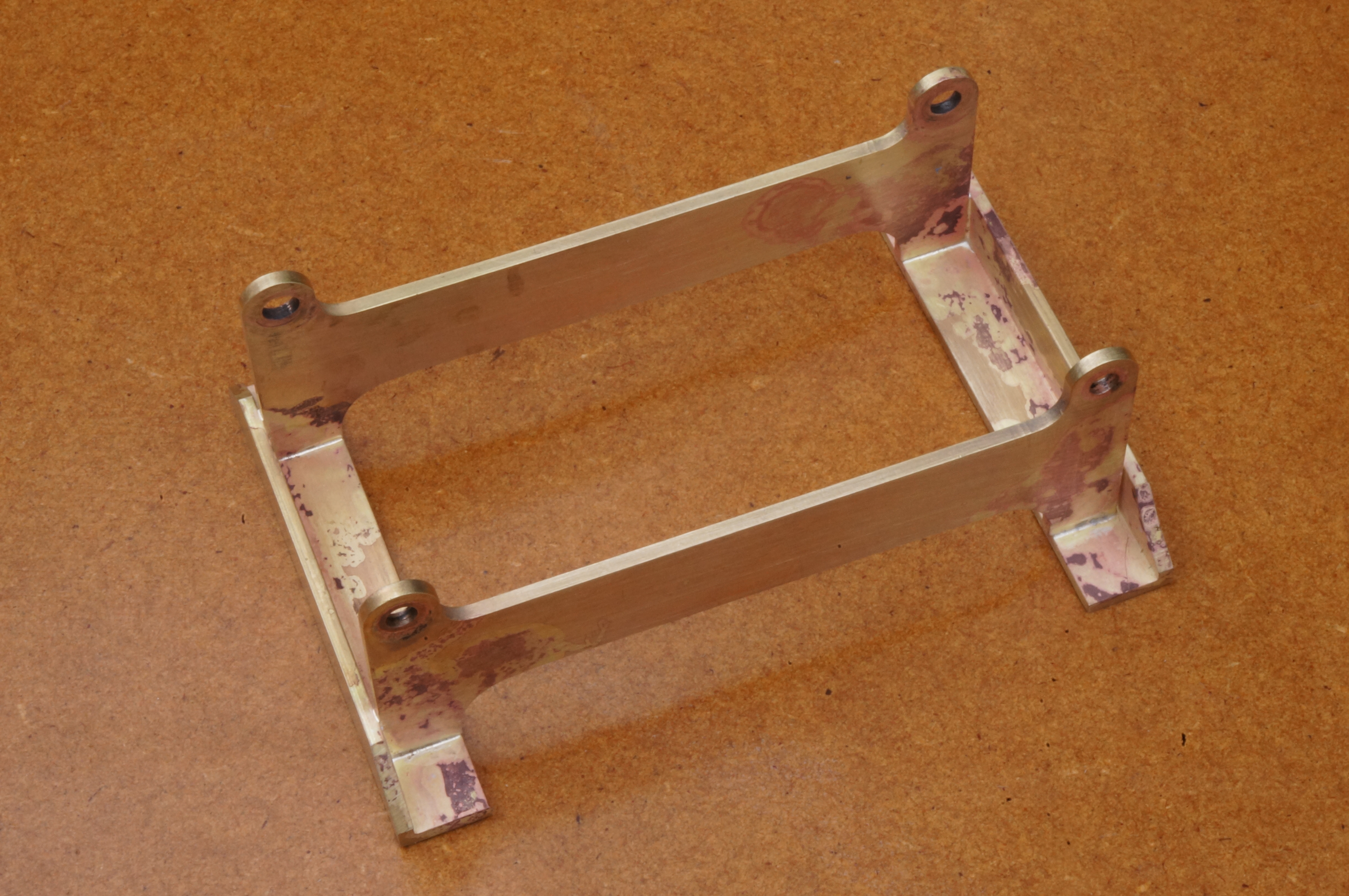
2020-05-01 – Soldering the stand
I used a pre-placed piece of silver solder wire bent to an L shape at each joint. I found they moved around as the flux dried and melted. Residual oil coming out of a spacer bar nearly spoiled one joint, and another had to be closed up with the first vaguely suitable tool within reach. The result is pretty good. The tabs and slots have worked well, but could have done with a little bit more solder. (¾ hour)
.
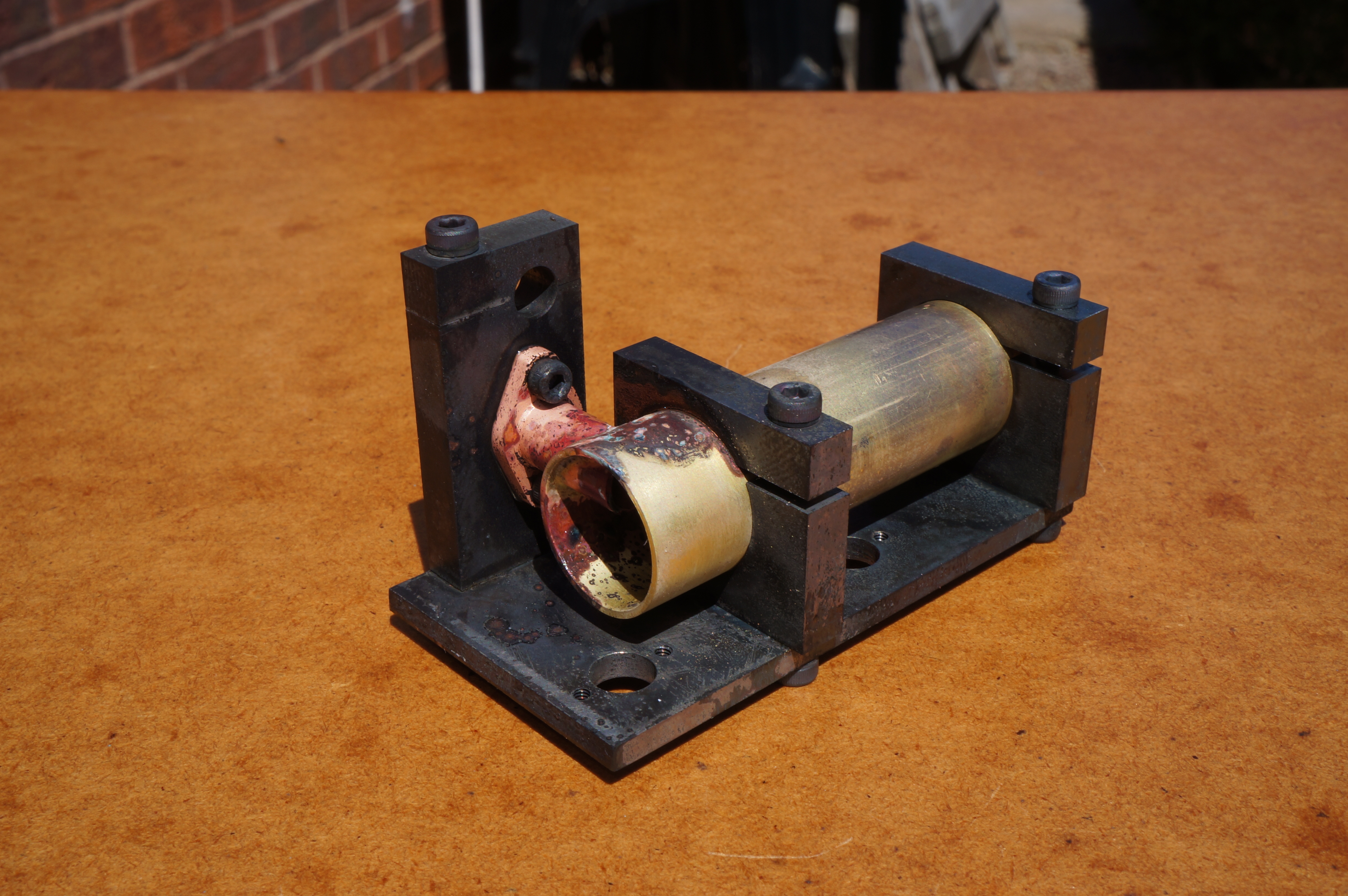
2020-05-01 – Trimming the radiator

It turns out that where the radiator sits in the stand it is slightly tapered, and the side I did not measure is too tight a fit in the stand. I milled a light shave off the edge flange and it now fits nicely.
I also drilled the fixing holes in the radiator stand, and started preparing it for paint. (2¾ hours)
More painting work is done at odd moments during the following weeks, but the time is either not recorded or not worth documenting.
.