
Cylinder Heads
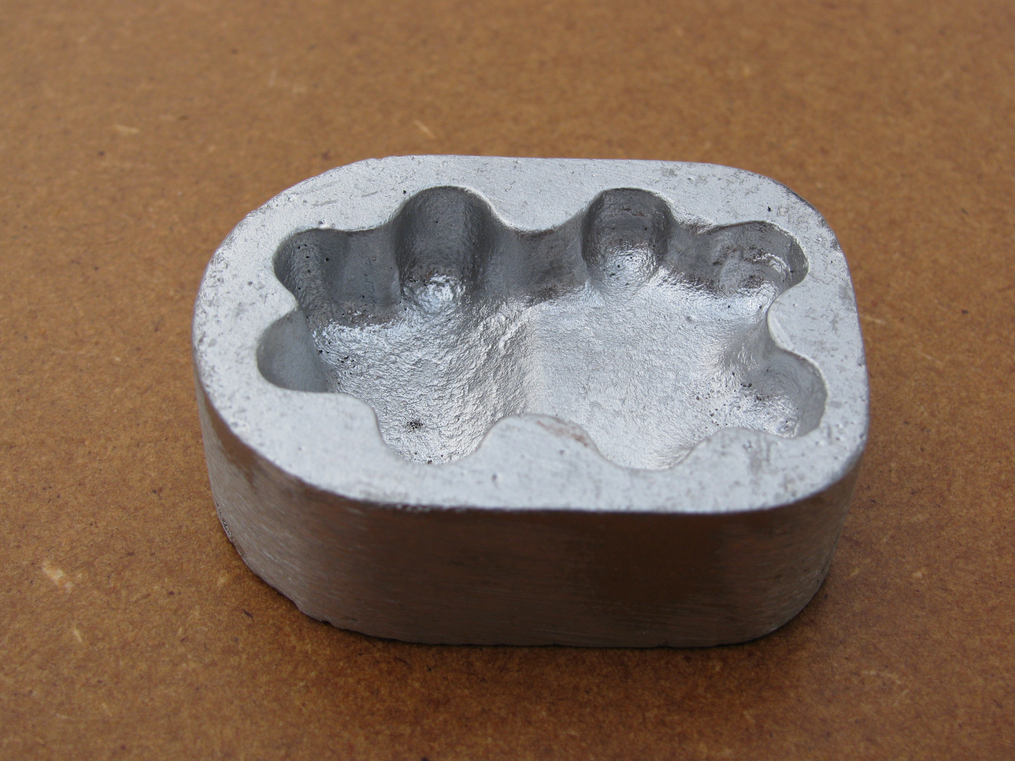
The castings have very little metal in some places. One has been over-enthusiastically linished and is about 15 thou under on one face, probably justifying a replacement.
Other watch points are round the sparking-plug holes and the fixing holes. Great care will be needed with the top and bottom face machining allowances to prevent the plug hole entering the water space. The extra metal the drawing shows in this area is not present on the casting. The plug will almost certainly have to be moved down by 1⁄32″. This is as far as it can go without making the wall too thin under it.
In the absence of any other indication that I can find, I have worked out from the drawings that the design compression ratio would be about 3.5:1. This seems very low, but that is probably what we want, for ease of starting and slow tick-over. I have since made enquiries about compression ratio, and it seems I should expect the engine to run perfectly well with this low a ratio.
Fortunately, the combustion chamber in the Hemingway castings is smaller than design and would give a ratio of 5:1 if the head were machined to leave the cavity at the depths shown on the drawing.
However, the castings are a bit short of metal round the plug, and to avoid a break-out into the water space, I may need to machine less off the underside and more off the top, increasing the chamber volume, perhaps to a compression ratio of 4:1. and it may be that the only way to avoid this would be to use the little #10x40 (3⁄16″) plugs instead of the ¼″ ones specified. The actual top-to-bottom dimension does not have to be ½″ anyway, and it may be better to leave it thicker to give more like the design 3⁄16″ water space over the valves.
It is interesting to note that the air-cooled head shown at the end of the construction series is designed for a considerably higher compression ratio.
The plug sealing face is also liable to cut into a bolt hole as drawn and will probably need to be moved away from the centre or, better, rotated slightly in plan. Reducing the 15° angle may also help.
The water passages from the cylinder will break into the upper water space only marginally and will probably have to be excavated by hand to make an even reasonably smooth passage.
The step in the roof of the combustion chamber seems mismatched on top and bottom sides. This may be intentional, to allow metal to be removed to alter the compression.
I discussed the problems with the castings with Kirk Burwell when I visited Hemingway to sort out a number of problems and to give him some feedback so far. He readily exchanged the head castings for a pair that will clean up to the plan profile. As it turns out, these two are a bit lopsided, in one case 40 thou thicker one side than the other, the mould halves perhaps not having seated properly. If the pair were lopsided so that they were handed, this could have been used to get a bit more metal round the plugs. Unfortunately the error seems to be systematic and they are both the same way. Careful measuring up shows that I can get enough metal to get a plug in safely by taking no more than about 45 thou off the underside, which will leave a combustion chamber 7⁄64″ deep instead of 1⁄16″ as drawn. This should give a compression ratio similar to design, but will not give the desired 'squish' to the charge.
In theory, the castings could be tilted across the width of the engine to reduce the depth of the combustion chamber, but there is little enough spare metal around the profile and sealing face widths as it is, and this idea seems an undesirable additional complication.
Kirk had also inherited some castings from Woking Precision in which that part of the water space above the valves is missing completely. He had assumed they were faulty and had put them in his scrap bin, but he found and gave me a couple. Later on, I can use these to make heads giving as a high a compression as I may want, milling out a water space as required.
Roughing out and re-examining seems to be a good plan generally, so I will file the bottom faces enough to seat nicely, take a cut off the top to get the faces parallel, then take 25 thou off the bottoms, and turn over again to bring them to 9⁄16″ thick.
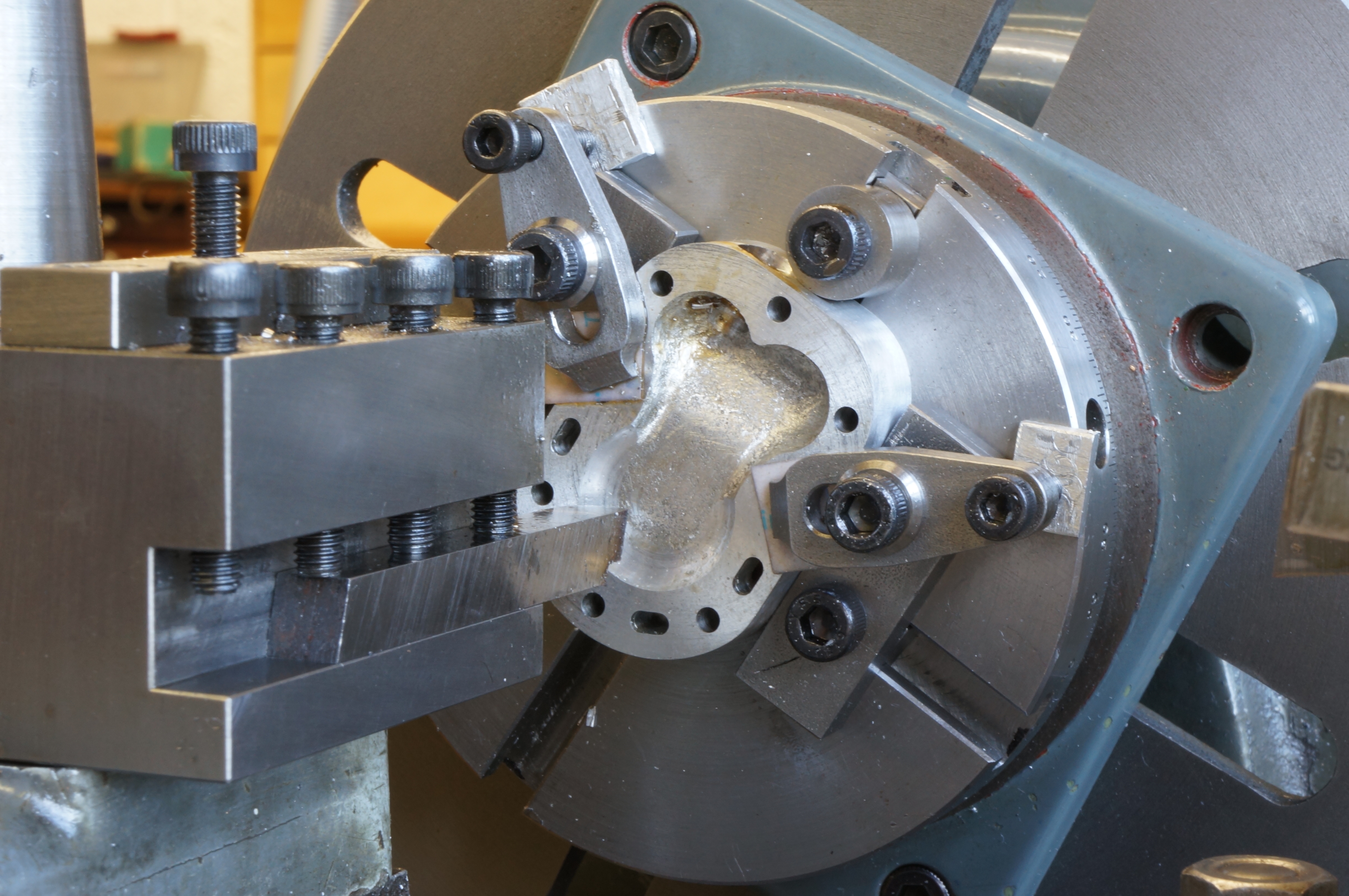
2010-07-24 - Initial roughing cuts
After doing the cylinder castings I decided to continue the bout of roughing out. After a little filing on the bottom face, I took a cleaning cut off the tops, reversed and took just 25 thou off the bottom faces, reversed again and reduced to a bit over 9⁄16″ thickness. (1 hour)

.
Much Later - can't find this section in my notes to put a date on it
On repeating the process of measuring up, now some metal has been removed and there are machined faces to work from, the 'B' casting is the more critical, and it will just allow 1⁄32″ of metal all round the plug hole if the combustion chamber is made 3⁄32″ deep. I decided to run over the surface of the combustion chamber with rifflers and a fine diamond tip in the Dremel to get close to the finished surface for measurements. Having done that I will machine them to 0.090″ to allow a little more polishing. I should perhaps leave a few thou for finishing cut on the critical sealing faces as the very last operation, just in case of a slip with hand finishing the cavities.
2013-02-02 - Roughing the spare pair
While thinking about what to do next during a short, late-afternoon session in the workshop today, I decided an easy job would be to rough-out the spare pair of heads. To clean the top faces up, parallel to the cast bottom face, I had to take a maximum of 80 thou off the first one. (½ hour)
2013-02-03 - Roughing the spare pair
The second one needed 60 thou off. As cast, the depth of the combustion chamber is 0.150″, so to clean up to the desired 1⁄32″ they would need almost 1⁄8″ machined off. As the thinner head is already down to a shade under 0.6″ this would mean it would end up less than the nominal ½″ thick. For the present, I decided to take just .060″ off the underside faces. I took the first cut off the second one with a rather aggressive feed, resulting in a built-up edge on the tool, which I did not notice, and which produced a poor finish on the final cut. A good thing these are just roughing cuts. (1 hour)
2013-05-04 - Setting up
I spent a little time at the end of the day setting up for milling the sides and ends of the head castings to finished dimensions. I managed to get the vertical slide square across the face to 0.0002″. The milling block has yet to be levelled. (1 hour)
2013-05-09 - Milling the first side
In places, there is quite a bit of metal to come off the sides of the head castings to bring them to the 15⁄16″ finished width. I took a cut of about 15 thou maximum off one side of each cylinder head, to establish preliminary datums. I need to work to the profile template, and particularly to get the combustion chambers central, as these are cast oversize in the region of the valves, coming very close to a head bolt, even after moving the bolt positions as much as possible to compensate. From here, I have worked all four heads together. I have not yet decided which head would be best for which cylinder, so I have designated the main pair A and B, and the spares C and D. (1¾ hours)
2013-05-13 - Second side and end
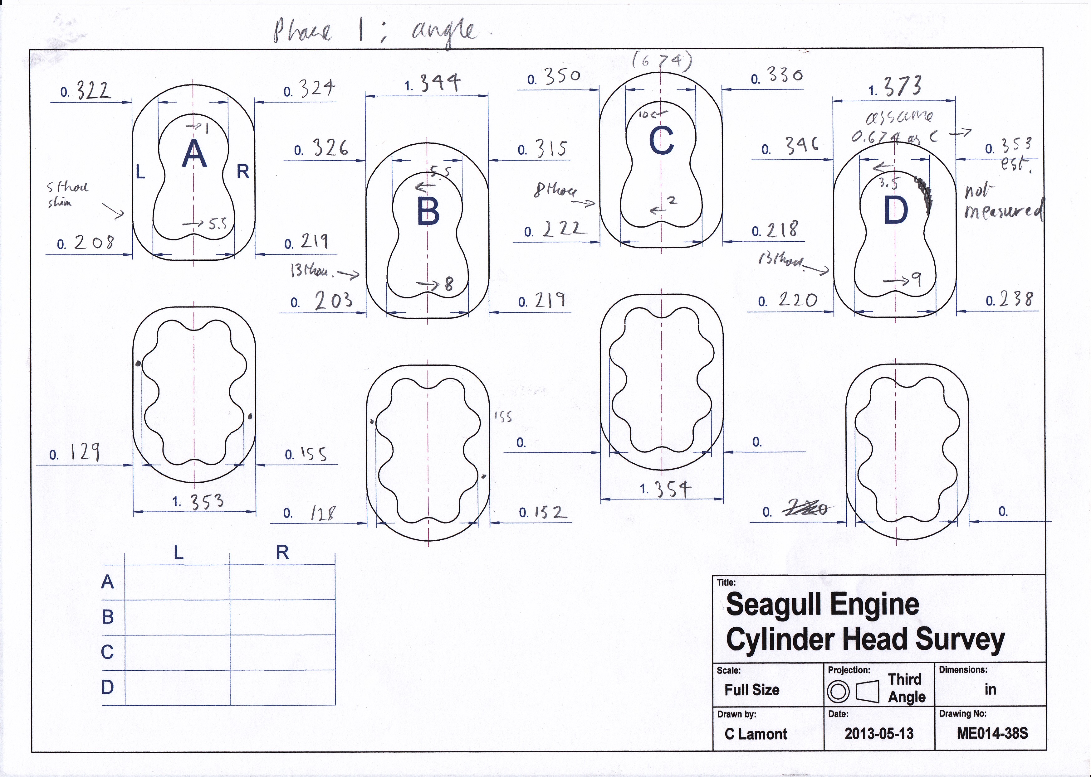
All the heads still have at least 0.050″ to be removed from the sides, so I took 15 thou off the second side of the narrowest, and decided to take 20 thou off the other three to get parallel sides that could be measured from.
Because of the critical importance of getting the combustion chambers centralised, I drew up a survey sheet and measured the distance of the cast cavity from the now machined side at four points on each head. This allowed me to work out if any rotation in plan was needed to align the sides with the combustion chamber. With D, part of the combustion chamber over the piston was not properly cored, so I had to guess the shape there. I also checked that there would be enough metal round the water spaces.
Using the figures derived from the survey, I shimmed one corner as required, and took a sufficient cut to cover the area already machined, and then machined the other side parallel. The D casting is very soft and machines badly. Dropping the cutting speed to 200 rpm improves matters. Although it looked bad, rubbing out the machining marks only took 3 thou off.
With the combustion chambers now squared up, I used a second survey sheet to adjust the final lateral position, working just from the widest point of the valve cavity. I then took finishing cuts each side, leaving a thou for hand finishing, and a bit extra on head D.
Finally, I set the vertical slide round at 90°, set the milling bar level, and took a light cut across the back (plug side) of each head, to get a datum. (7½ hours)
2013-05-18 - Ends rethink and measuring for facing
It has not been possible to clean up the plug faces of the heads over the nominal 7⁄16″ width, while still allowing enough overall length to meet the full profile round the arc of the water jacket. The profile template provided the clue as to what could be done. I mistakenly made this 0.010″ short. By taking a further 10 thou off the plug side of the heads it would probably enable them to clean up properly. The bolt bosses on the covers can be reduced to 0.230″ diameter rather than the ¼″ I had been working on, and would probably look neater for it. Also it would allow a distinction to be made between the cylinder portface and the surrounding area, making a better looking job. After adjusting the drawings and checking the castings I decided that was the way to go and machined all the heads accordingly.
Next, I did a bit of work on the C & D combustion chambers, cleaning out and smoothing the surface with the Dremel to allow better depth measurements to be made in getting the heads closer to finished thickness.
Measuring the heads to see how to finish them for thickness, I first looked at head C, which is the thinnest. This was 0.534″ thick, allowing 1⁄32″ to be machined off, leaving a thou for lapping each face. The combustion chamber, in the flat area over the cylinder, is 0.091″ deep, so with 0.032″ machined off and a lapping allowance, it would end up with a combustion chamber at 0.058″ deep, a shade less that the design 1⁄16″. With head D, the combustion chamber is one thou deeper, so machine 0.033″ off this side, leaving 0.047″ to come off the top.
Turning to A & B heads, the prime consideration is leaving enough metal over the sparking plug hole; that will determine the combustion chamber depth. The maximum allowable depth of the water space over the plug is 0.172″ (11⁄64″). A slight variation in the depth of the water space across the width means that there is a slight advantage in using A for No 1 Cylinder and B for No 2. This way, both currently have 0.195″ over the plug, so they must have at least 0.023″ thou taken off the top face. Considering A, which is slightly thinner, this would leave 0.038″ to come off the bottom, leaving lapping allowances. The combustion chamber would finish up 0.093″ deep, exactly as expected (and 50% deeper than design). For B to come out the same, it will need 0.036″ thou off the bottom and 0.030″ off the top, which is OK from the point of view of the plug hole.
The heads will still need quite a bit of work doing after facing, such as drilling for the plugs and head bolts and milling the water ways, but the faces, particularly underneath, need to be perfect so it may be better to leave a little bit of metal on for a very last operation. In the end I decided to finish the top faces to lapping allowance but to leave an extra 5 thou on the underside, so each should end up 0.507″ thick.
So, I took 0.027″ off the bottom of C, leaving it 0.507″ thick. Taking 0.028″ of the bottom of D left it 0.542″ thick, so it needed 0.035″ off the top. I took the final 5 thou cut off this soft and difficult casting at 200 rpm, smeared with Rocol RTD paste. The result was not bad at all. Getting things dead parallel when seated against the steps of the chuck jaws is tricky, and in this case there was a thou variation. Finally I did the bottoms of A & B heads. (4¾ hours)
2013-05-20 - Checking
In as short session today I checked the measurements on A and B, checking the deepest part of the combustion chambers as well as the shallow part above the piston. A needs 0.022″ off the top and B needs 0.029″, confirming the earlier measuremements. (¼ hour)
2013-05-29 - Last facing cuts
This afternoon I faced the tops of A and B heads, as worked out above, resulting in both being a shade over 0.507″ thick.
2013-05-30 - Plug Holes

The first thing I did today was check that my ¼ x 32 TPI tap would produce a suitable hole for the plugs. I cut off a little piece of alloy bar and drilled and tapped a test hole. The thread on the plugs is not brilliant but the fit is OK, if a bit looser than the ideal.
With that check done, I set up for making the holes in the heads. I was able to jam a 3⁄8″ thick packing piece in a t-slot in the swivelling vertical slide to align the heads against. It would have been easier with the packing piece in the bottom t-slot but there was no room. I checked it for level, and swung the slide round to the 15° angle of the plug holes. Clamping the head in position was still a bit awkward. Notepaper between the job and slide gives a better grip and protects the finish machined face.
Having marked the heads to be sure of getting one of each hand out of each pair, I set head C flush with the edge of the slide, for repeatability if needed and set the hole position from the lower side, feeding the table down and back up to position for backlash. For the position horizontally, across the thickness of the head, I measured from the exposed edge, with the distance to move the cross-slide taking account of the remaining machining allowance, and the 15° angle.
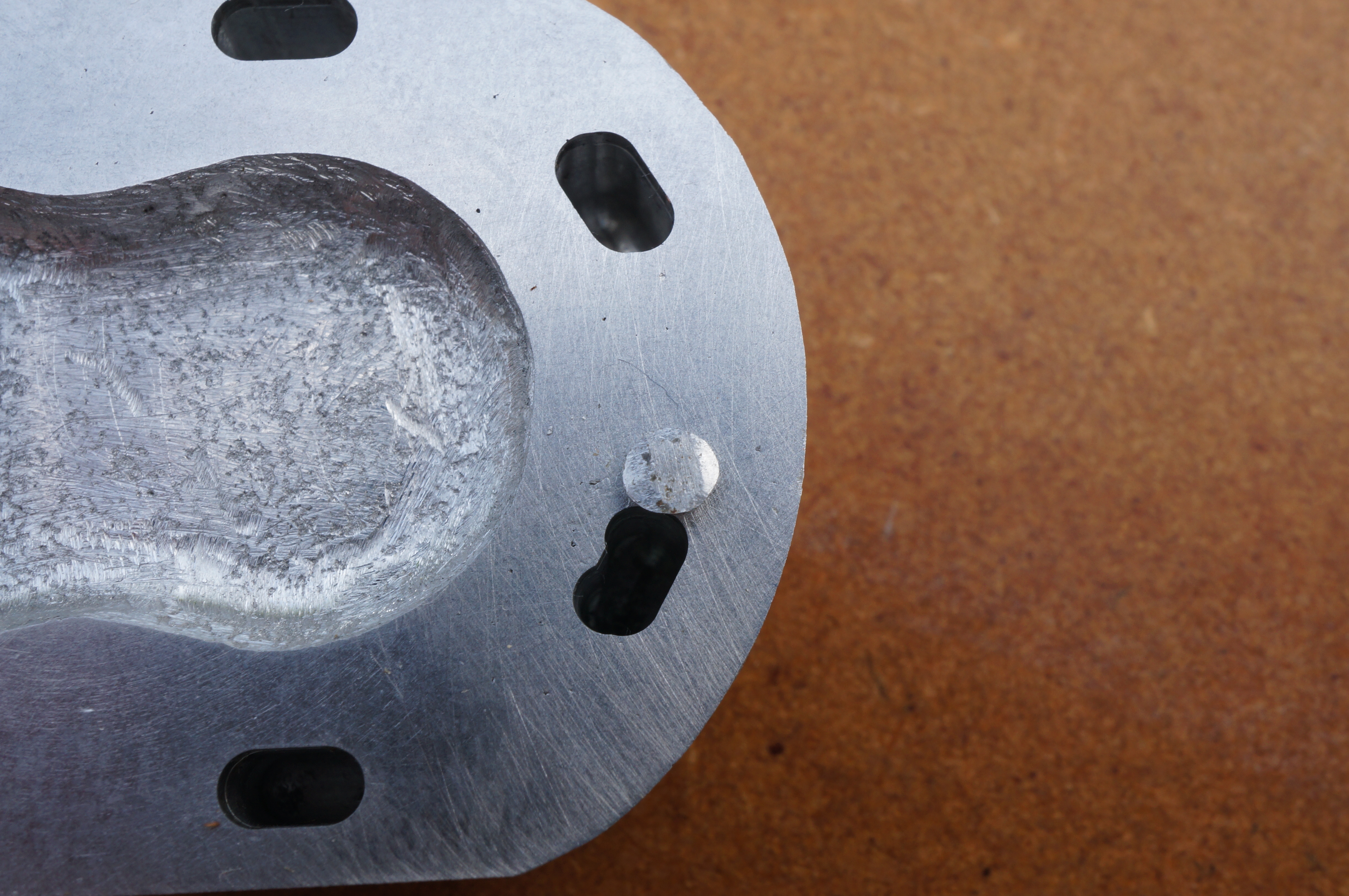
I marked the face with a centre drill and sanity-checked the position with a rule, then counterbored the sealing face with a 5⁄16″ slot drill, drilled 5.2 & 5.4 mm, counterbored just a touch with a 6.3 mm drill and tapped 2nd and plug for eight full threads. The result looks OK, but there is not a lot of metal left under the hole, even before finishing. Next, I did the same with head A, but tapped just six threads deep, which is enough for the plug, as Westbury warns against exposed bits of thread inside the combustion space. After resetting the vertical slide for the opposite hand, I made the holes in heads B & D. (4 hours)
2013-06-02 - Locating strips
For machining the waterways in the heads there is no suitable hole to line them up on the rotary table, so I made a pair of steel strips which will be used to locate the heads on the table. (1¼ hours)
2013-06-29 - Waterways

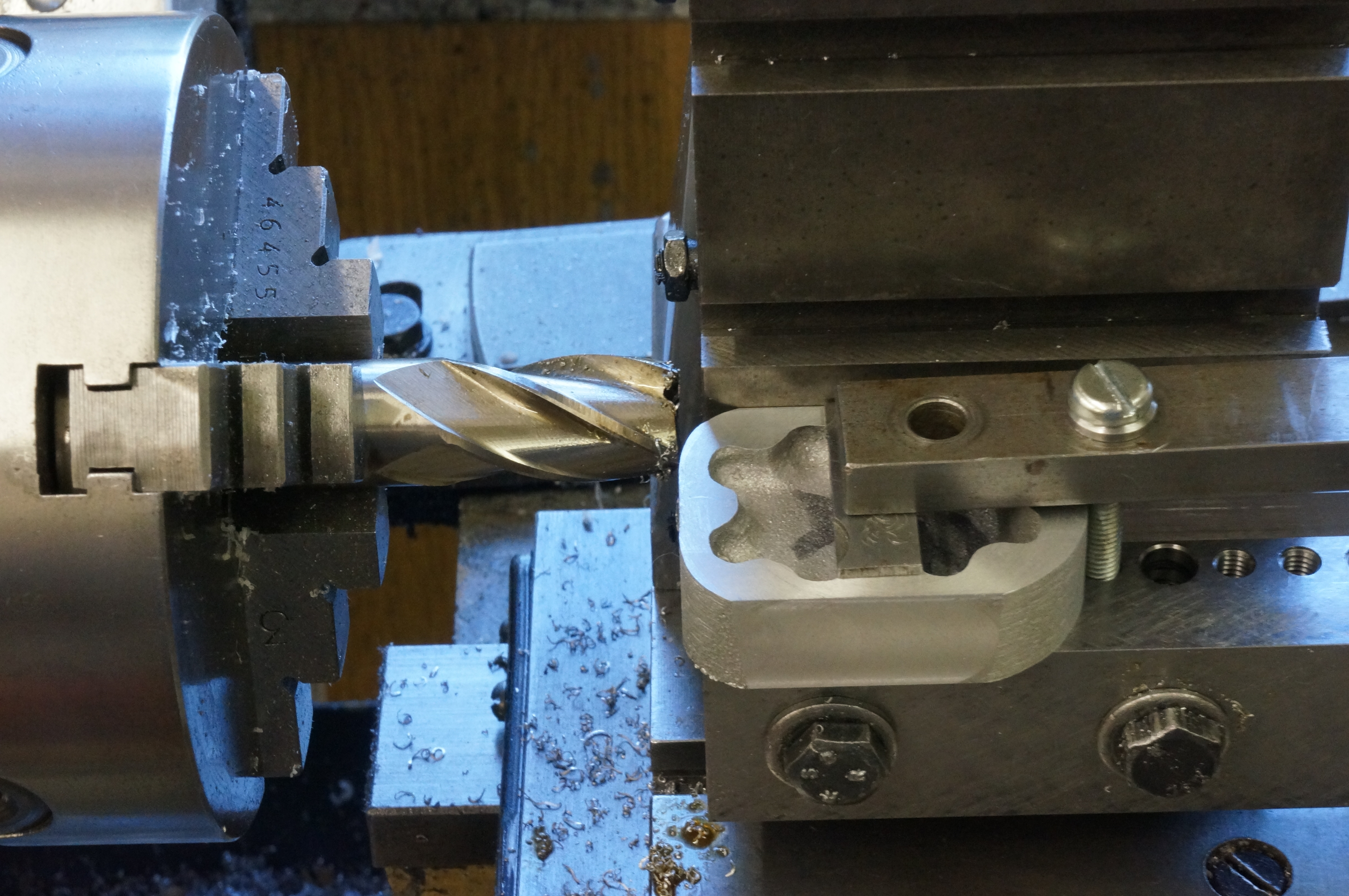
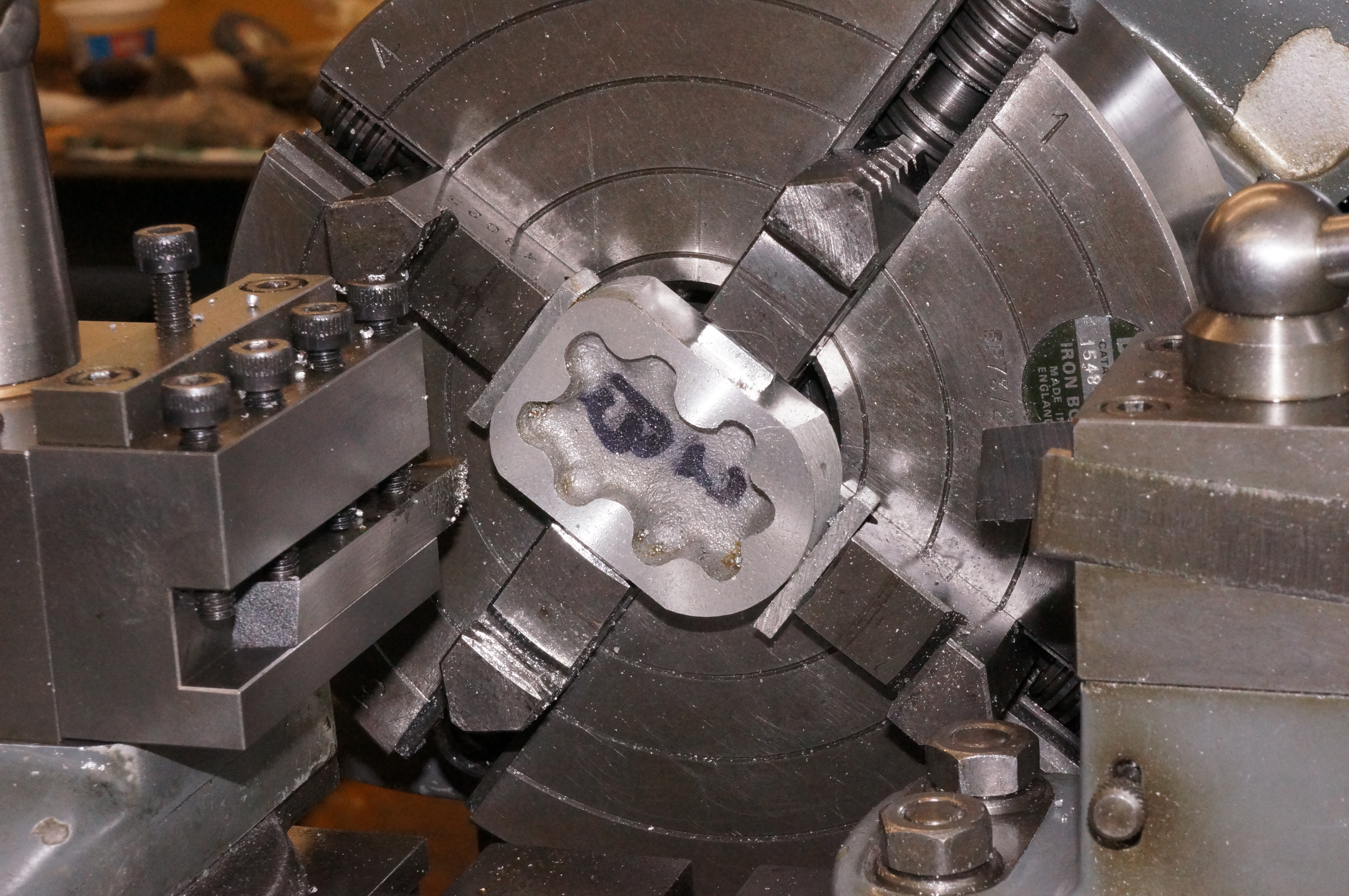
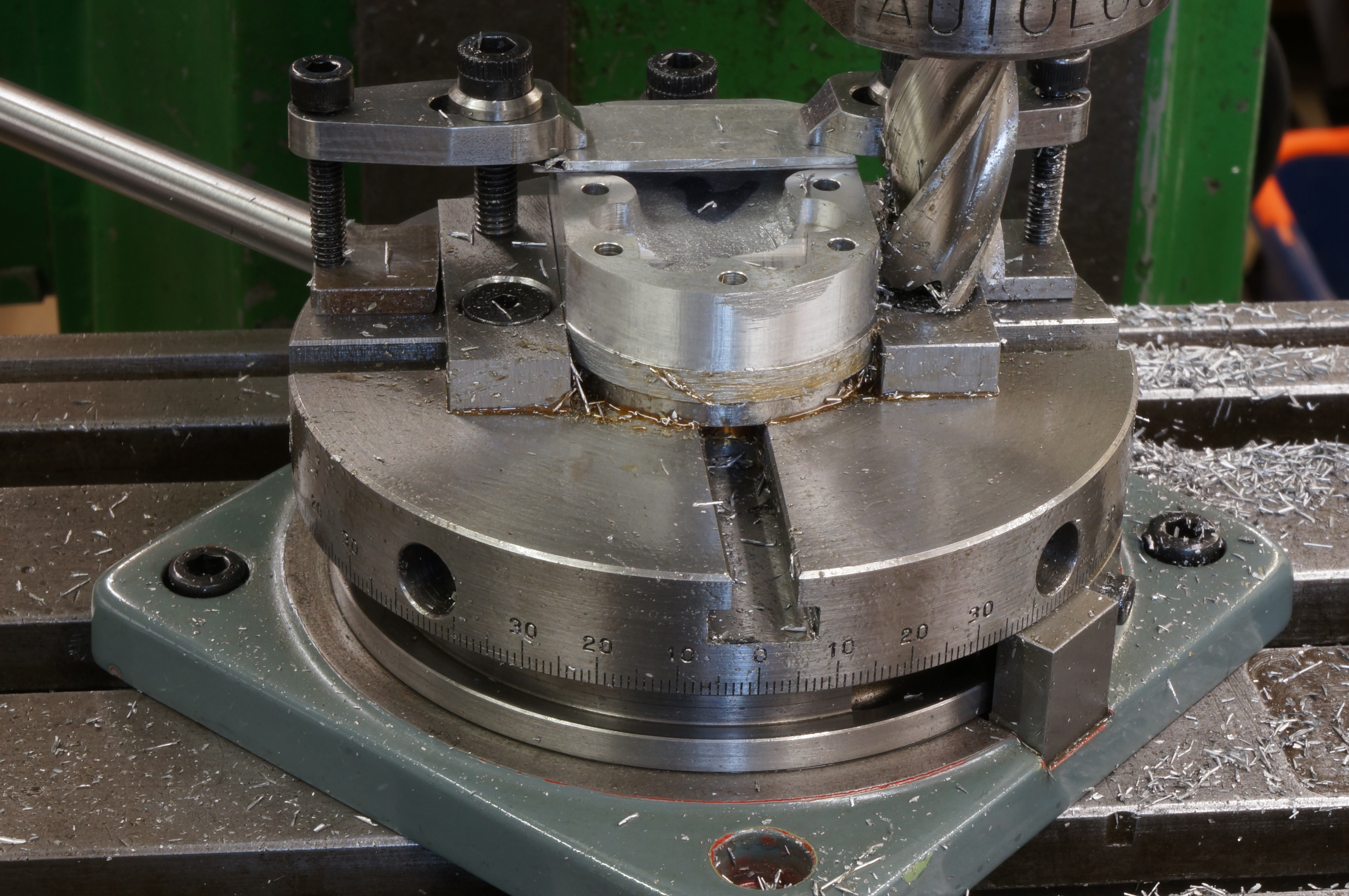
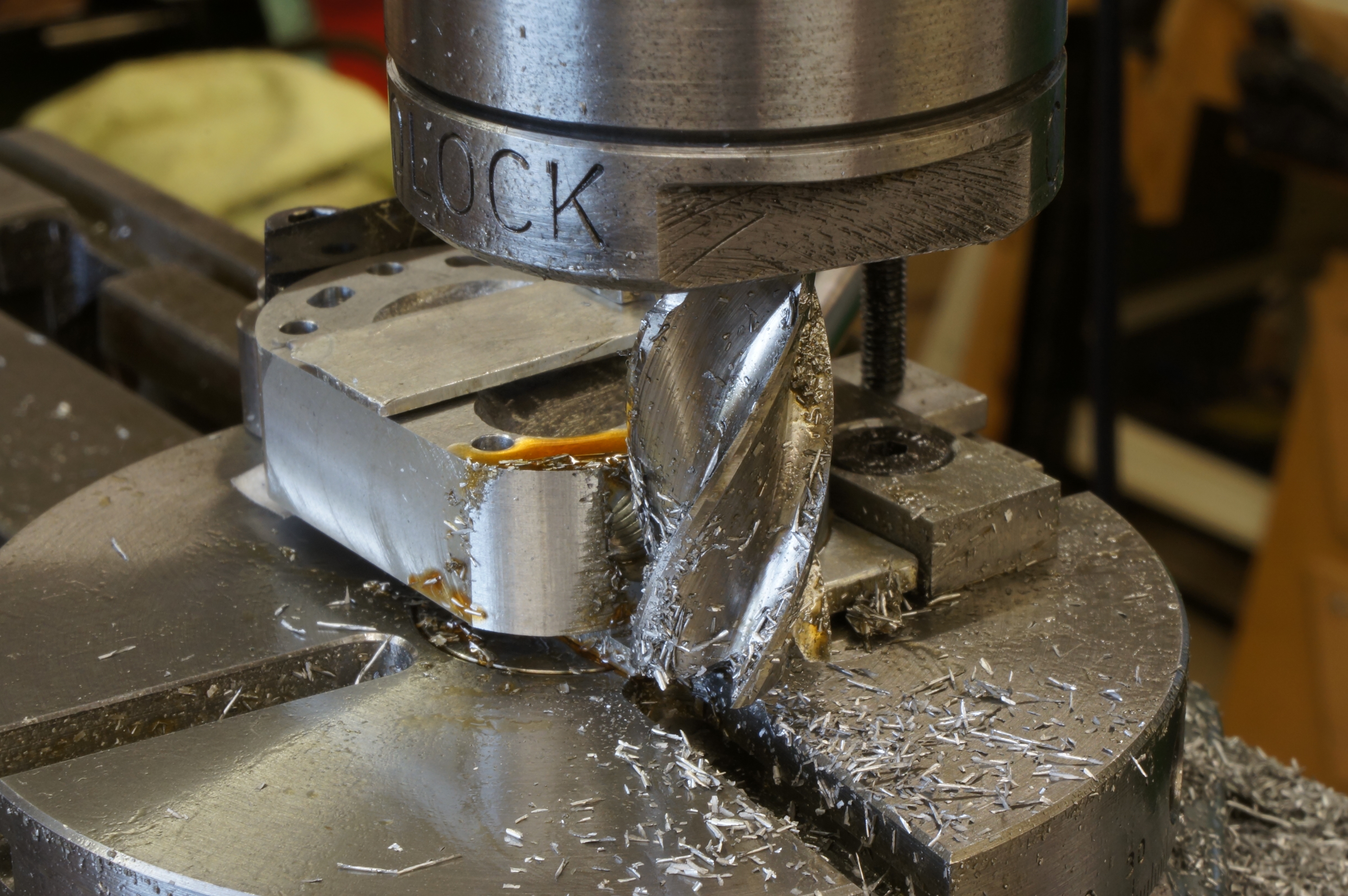
With the vertical slide set square and the rotary table zeroed, I used the cylinder profile template, with cigarette papers, and a large square, to position the two locating strips on the rotary table. A single bolt with a larger nut formed the end stop. After removing the locating pin and template, I clocked the hole in rotary table on centre and zeroed the slide dials. I lifted the vertical slide 17⁄32″ to give the correct radius for the slots, and wound the cross-slide out and in again to -0.045″ for drilling the first hole. The procedure was exactly as for the corresponding slots in the cylinder barrels. I worked at top speed with the VFD in 'overdrive', giving a nominal spindle speed of 2600 rpm.
The first head to be done was C. Examining it afterwards I found that one slot had broken through a little, with two more daylight was just visible, and one was completely blind. I drilled this one through from the water space by hand and then excavated with the Dremel, mainly using a carbide burr. At 5⁄16″, the slots are machined plenty deep enough but, rather as expected, work will be needed on the water side. (3½ hours)
2013-07-22 - Waterway disaster
The next head to be milled was D. In this case none of the holes broke through.
Working next on head A, and returning to it after lunch, on the third hole I managed to wind the cross-slide the wrong way, and drilled a hole without checking. First I considered filling the hole with with JB-Weld as I was worried that if I carried on with milling, it might break through. After dithering for a while I decided to cut the fourth slot anyway.
.
2013-07-23 - Disaster recovery
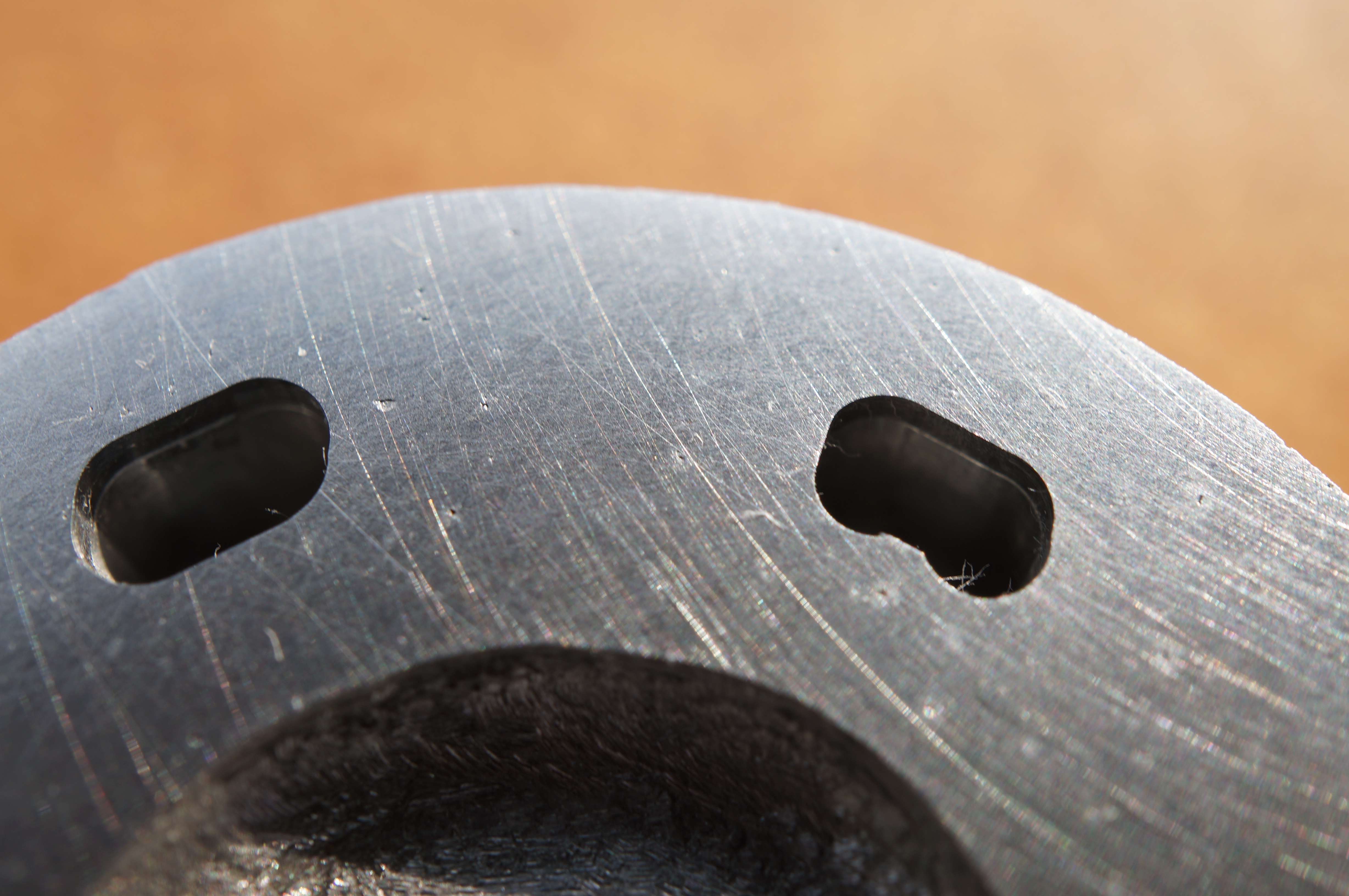
So, what to do? If the slot were cut 0.15 mm short, just to the edge of the existing good hole then it would not break into the 'extra' one. So that is what I decided. Although it will not be seen, and will not materially affect the function of the part, I want to do as neat a repair as possible. I can claim it is for the value of finding out how good a repair I can make, rather than admitting I am trying to hide the cock-up even from myself. I am thinking of making a plug in aluminium alloy.
Having put the part back in the lathe and milled the slot I found another problem. The slot does not match up properly with the drilled holes. I put head A to one side for a think, and carried on to cut the slots in B, which went fine.
Clearly, what had happened was that when first set up, head A was not touching the end stop. I set it up again, in the correct position this time, and re-cut all the slots, so there would be no overlap of the slots in the cylinder. The result is that the two side slots are a bit longer than they should be, and the slots on the arc are a bit wider, and trapezoidal (or parallelogramic if one prefers). The slot accepts the shank of a 3.00 mm drill, while a 'good' one takes a 2.6 mm. This means the displacement was about 0.4mm or 1⁄64″. The slot is still less than 1⁄8″ wide, the size of hole shown by Westbury. This is all very irritating, but I think it will actually be perfectly all-right. I don't fancy making another one at present.
After tidying up and attending to a domestic repair, I turned an alloy peg to go in the unwanted hole. I made it with a slight taper. After treating the hole with Loctite cleaner I used Loctite 603 to fit the peg, pressing it firmly home with the vice and then hammering it to ensure it swelled to a tight fit. Finally I filed and then rubbed the peg flush, using plain paper over the abrasive to protect the main surface (which has yet to be finish machined anyway). (3¾ hours)
2013-07-28 - Water spaces
The spare head castings have no cast-in water space over the valves, so they need to be milled to extend the existing cavity. At the same time the recesses at the other end can be cleaned out to open up the water passages. In preparation for this work, I off-hand ground a 3⁄32″ radius on the cutting edges of a 5⁄16″ slot drill, a job that was trickier than I expected. (1 hour)
.
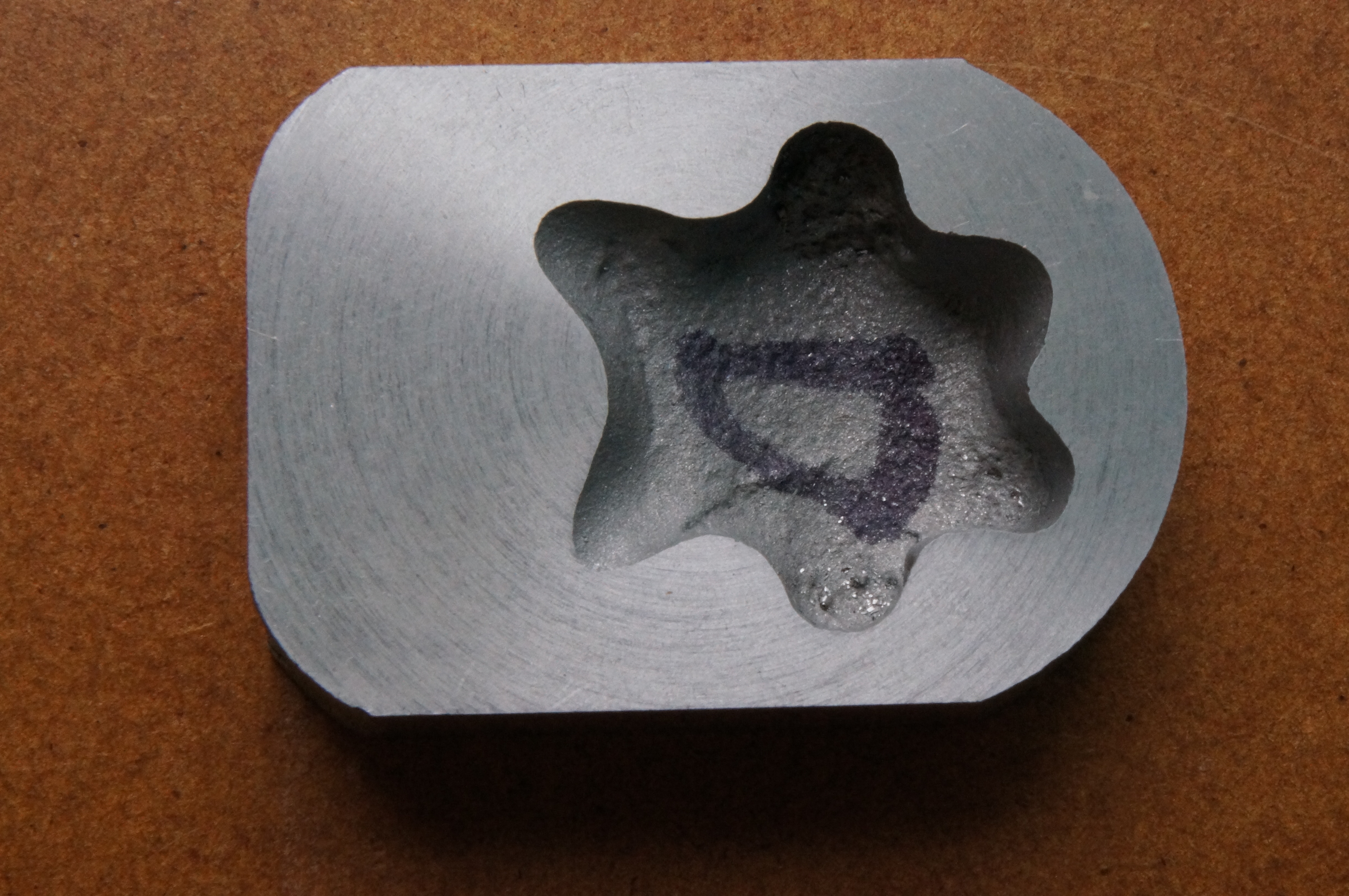
2013-08-05 - Water space milling

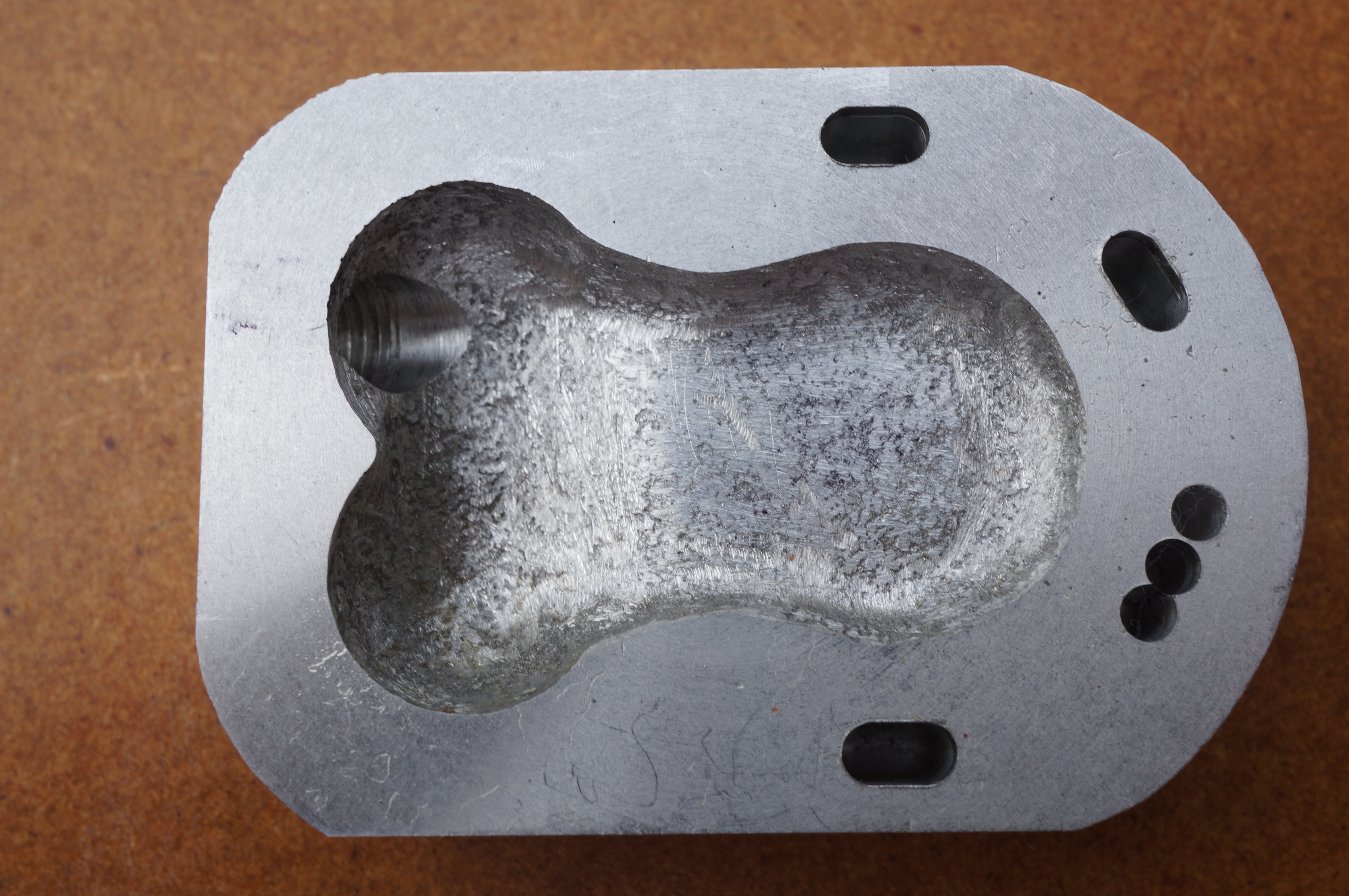
There is quite a large variation in the depth of the cavities in the spare heads. Starting with head C, this will take 0.325″ at the 'deep end', and both will be 5⁄32″ deep at the 'shallow end' over the valves. With Head C completed I went on to do D. This only needs a maximum depth of 0.275″. Measuring the thickness at the shallow end, D is about 0.165″ thick, while C is around 0.115″. While this seems a bit thin, I think it will be OK. I finished off by lightly relieving the edges where the water passages emerge, using the Dremel. (3 hours)
2013-08-24 - More water space milling

Today I completed milling the A & B heads, at the deep end only, to open up the water passages, milling both to a depth of 0.280″. This means they will have a minimum thickness in this part of a shade over 1⁄8″. Again, I eased the passage edges with the Dremel. (2¼ hours)
The next job is drilling, and for that I am making a jig.
.
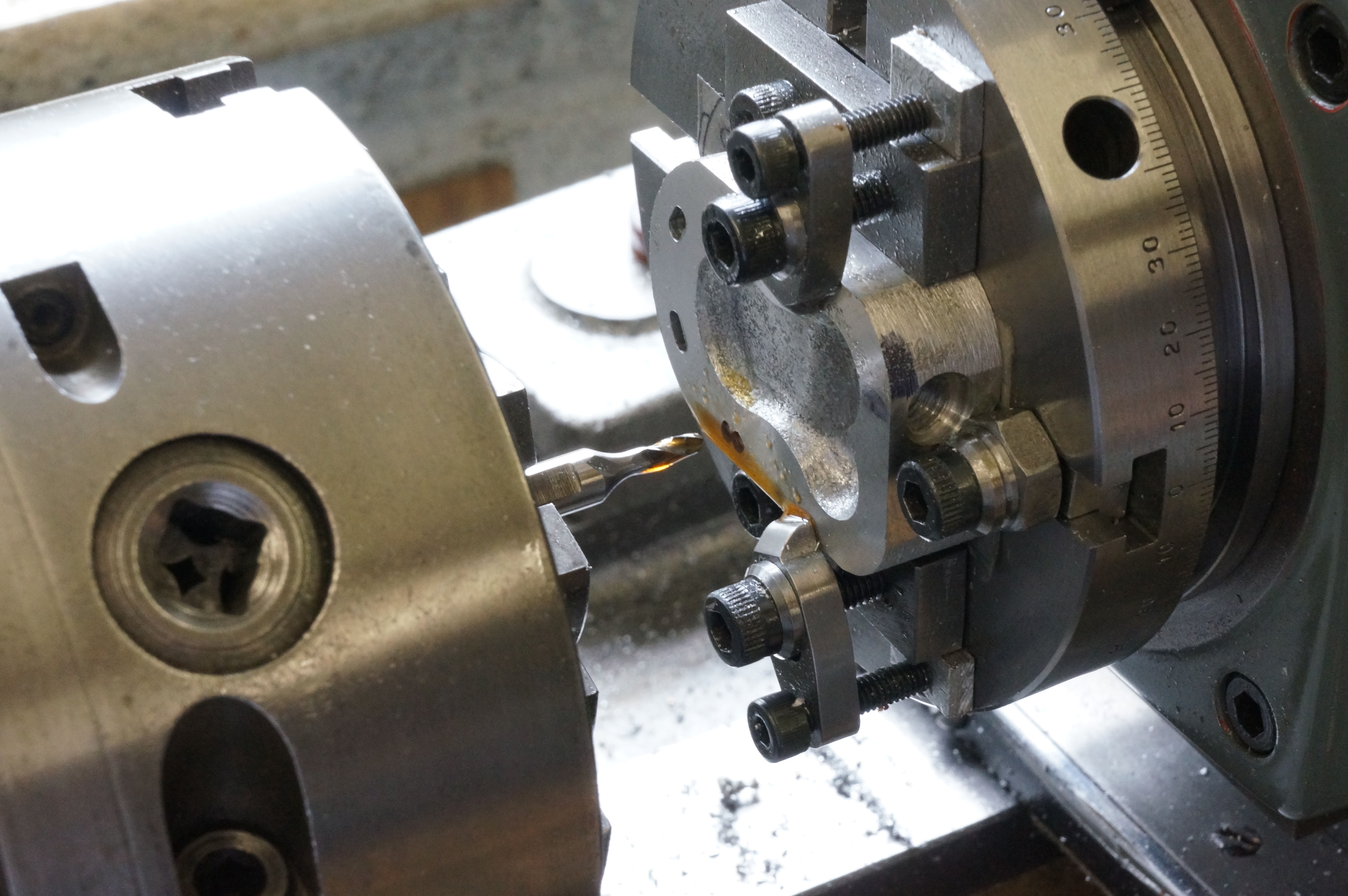
2014-03-28 - Drilling
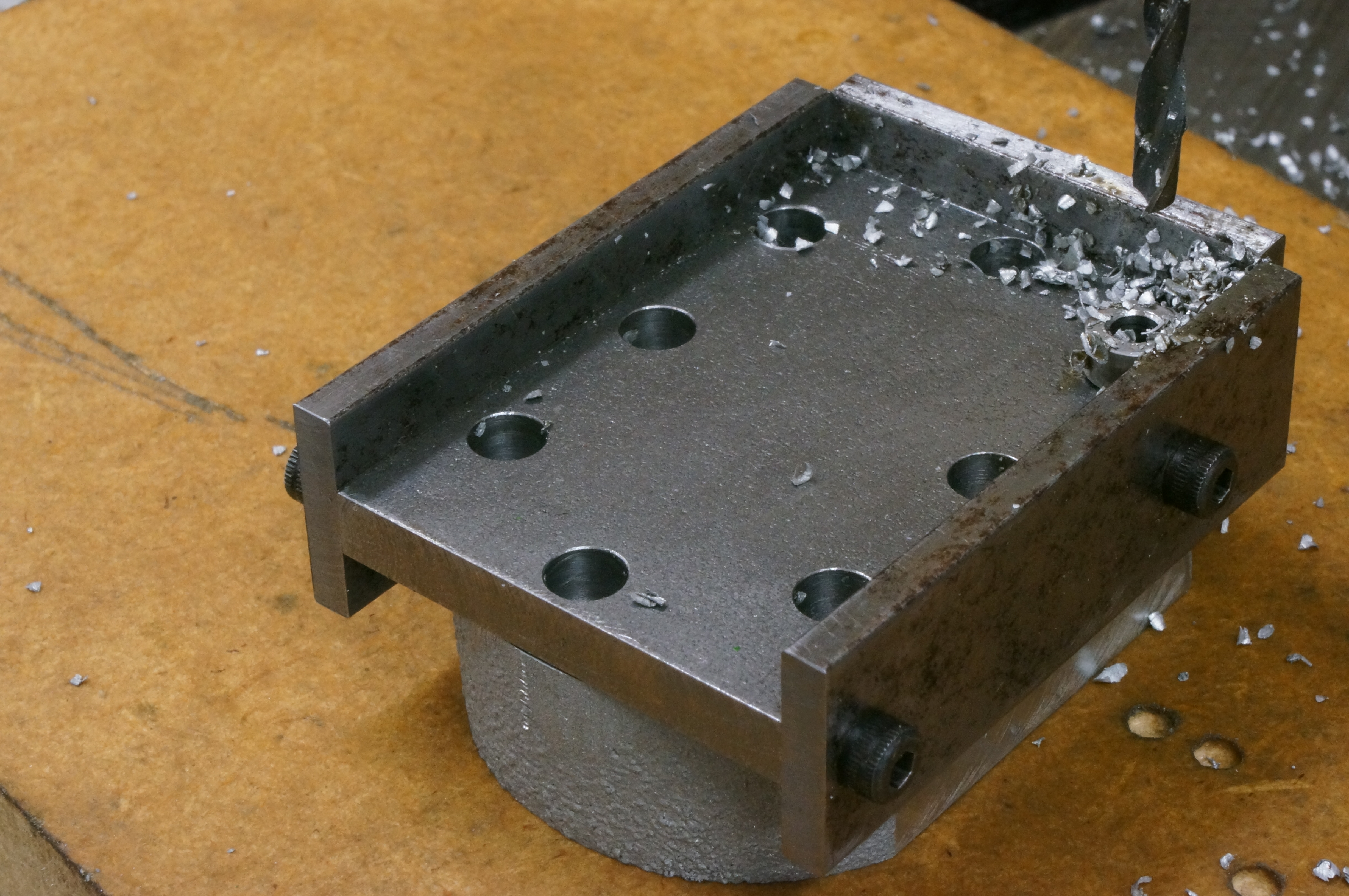
The jig locating fences allow the head to be fitted below or above the jig so that drilling can be done from both sides with the same jig hole always used for each head hole. I arranged it this way to minimise the effect of any tendency of the drill to wander. In drilling the No 1 (A) head, I found I could only peck a depth of about 1⁄32″ at a time before the swarf jammed in the drill bush, causing some wear on my left index-finger nail which I was using to retain the bush. After lightly deburring and cleaning up, I found the head would fit over the studs very nicely. As expected, the holes either side of the valves do end up rather close to the combustion chamber. (1 hour)
2014-03-29 - More drilling
In a short session today, I drilled No 2 head, which also fits either cylinder, either way up. (¾ hour)
2014-03-31 - Drilling again
Today I drilled the C & D heads. While blowing the swarf away with an air jet, I blew the drilling bush away too. After spending an hour trying to find it, I gave up and made another. The workshop floor is well swept anyway. This bush was a slightly looser fit in the jig, but the heads fit fine. Tidy up. (estimated 2½ hours)
2014-04-07 - Profile milling
The set-up for cosmetic milling the shape of the heads was much the same as I used for milling the water ways, again using the cylinder profile template to set the positions of the side guides and end stop. To provide clearance for the milling cutter, I had to use countersunk screws to hold the locating strips on to the rotary table. It took nearly an hour and a half to do the setting up, but once done, all four heads were milled, top and bottom, in slightly less time. I used a 9⁄16″ end mill, running at 800 rpm, taking cuts of 15 thou at a time and a 5 thou finishing cut, with RTD liquid.
Milling the 'back' corners needed a slightly different set-up, with one of the locating strips removed to allow tool access. Fortunately, the template has locating holes on the valve centrelines, and the back profile radius is based on the same centreline as the valve, but in my case moved in 0.010″ hence the shim between the end stop and the job.
Next job: do the same on the Cylinder Covers. (4¾ hours)
In the following months, I did a lot of hand work to make the all the cylinder castings look a bit better. However, once the profile milling work above was done, there was not much to be done on the heads, apart from blending the large radii to the side flats and removing machining marks. The tedious hand fettling work is therefore mostly covered (tediously) at Cylinder Barrels.
2015-02-20 - Plug hole plug
I made a dummy plug to protect the plug hole during sand blasting. Then I made another one with the correct 32 TPI thread, instead of the 40 TPI which I had carefully screwcut on the first one. (1½ hours)
2015-03-01 - Final facing
The drawings show the combustion chamber above the pistons as having a 3⁄8″ radius to match the bores. Indeed, Westbury changes his mind on the air-cooled heads, and gives them an extra 64th for clearance. There is a theoretical clearance between the piston crown and the bottom of the cylinder head provided by the désaxé geometry, but it is only 0.004″, and I would not want to rely on it. The as-cast combustion chambers are quite a bit smaller, and need enlarging. I don't fancy trying to do this by hand so the cavity will be machined.
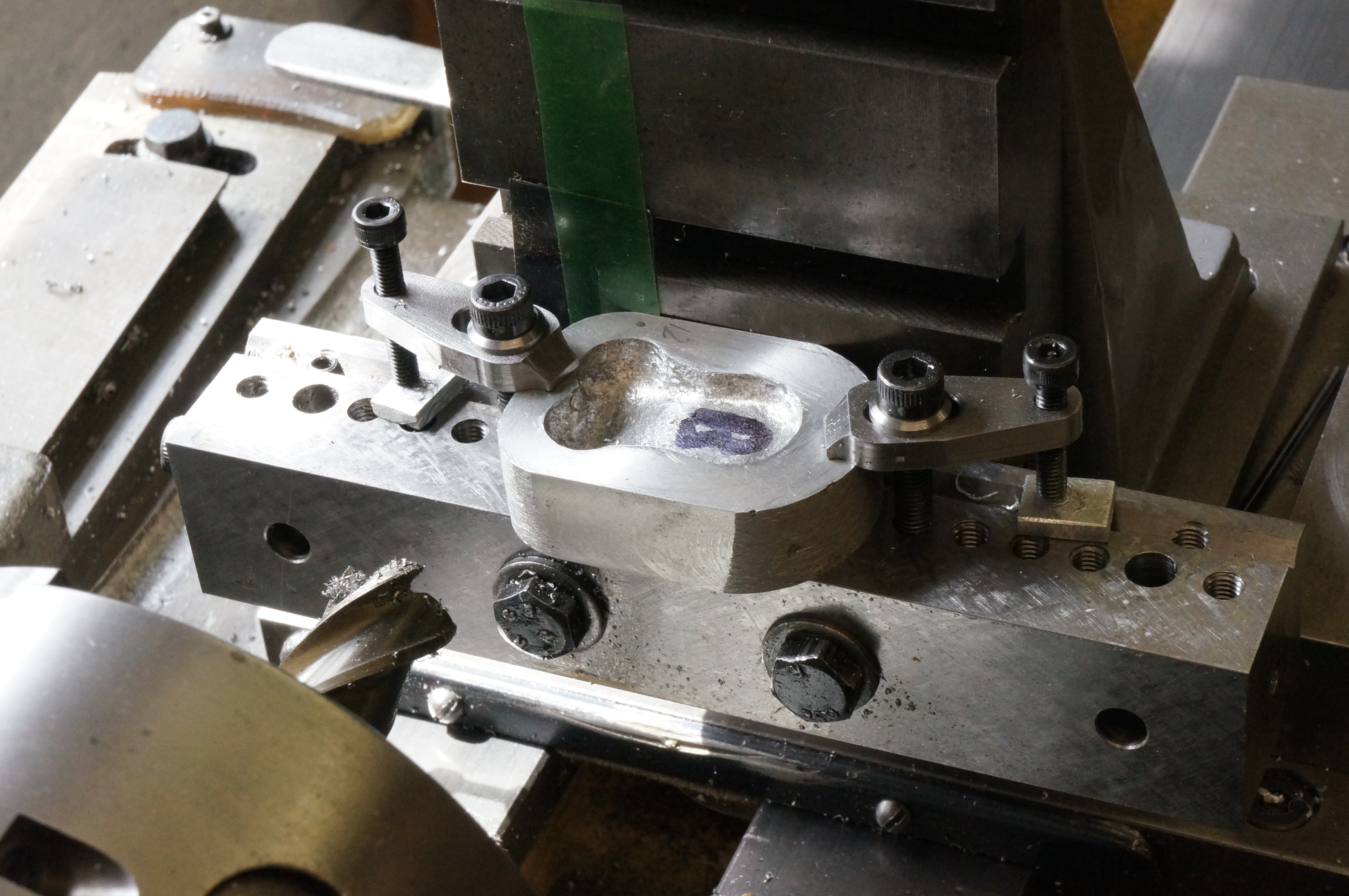
After a lot of thought about possible set-ups, I decided to finish the bottom faces of the heads, and clean out the combustion chambers as separate operations. The facing does not need accurate location but the combustion chambers do need to be accurately centred, and as there are four of them, a jigged setup is desirable if it does not create a lot of extra work, and the best I can come up with needs to use the faces for clamping the head in place.
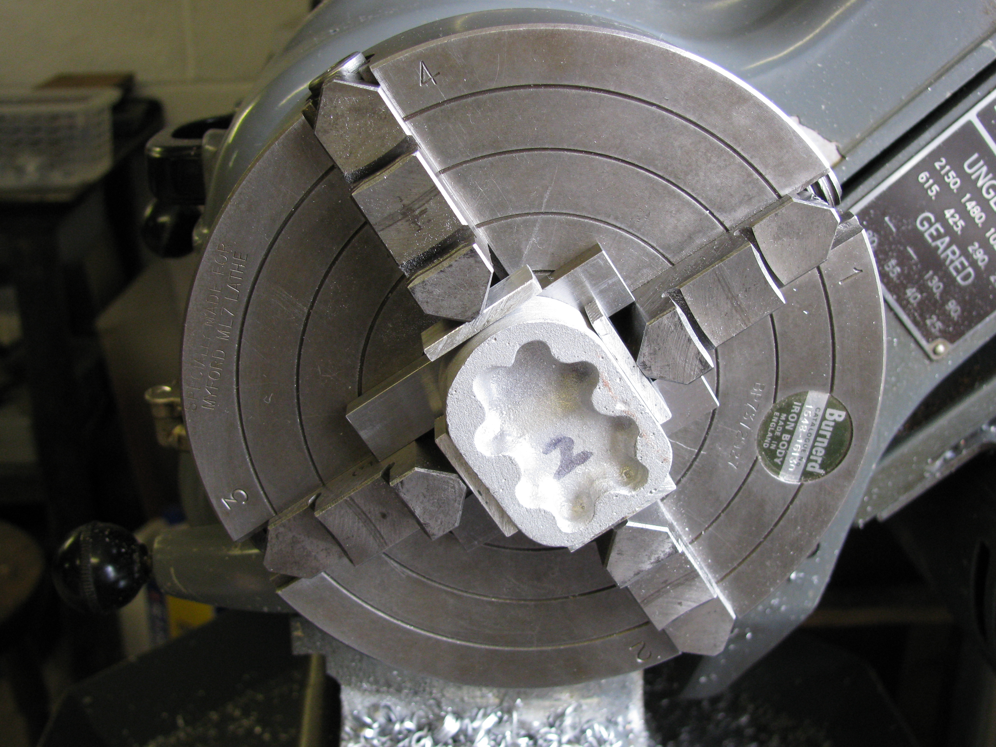
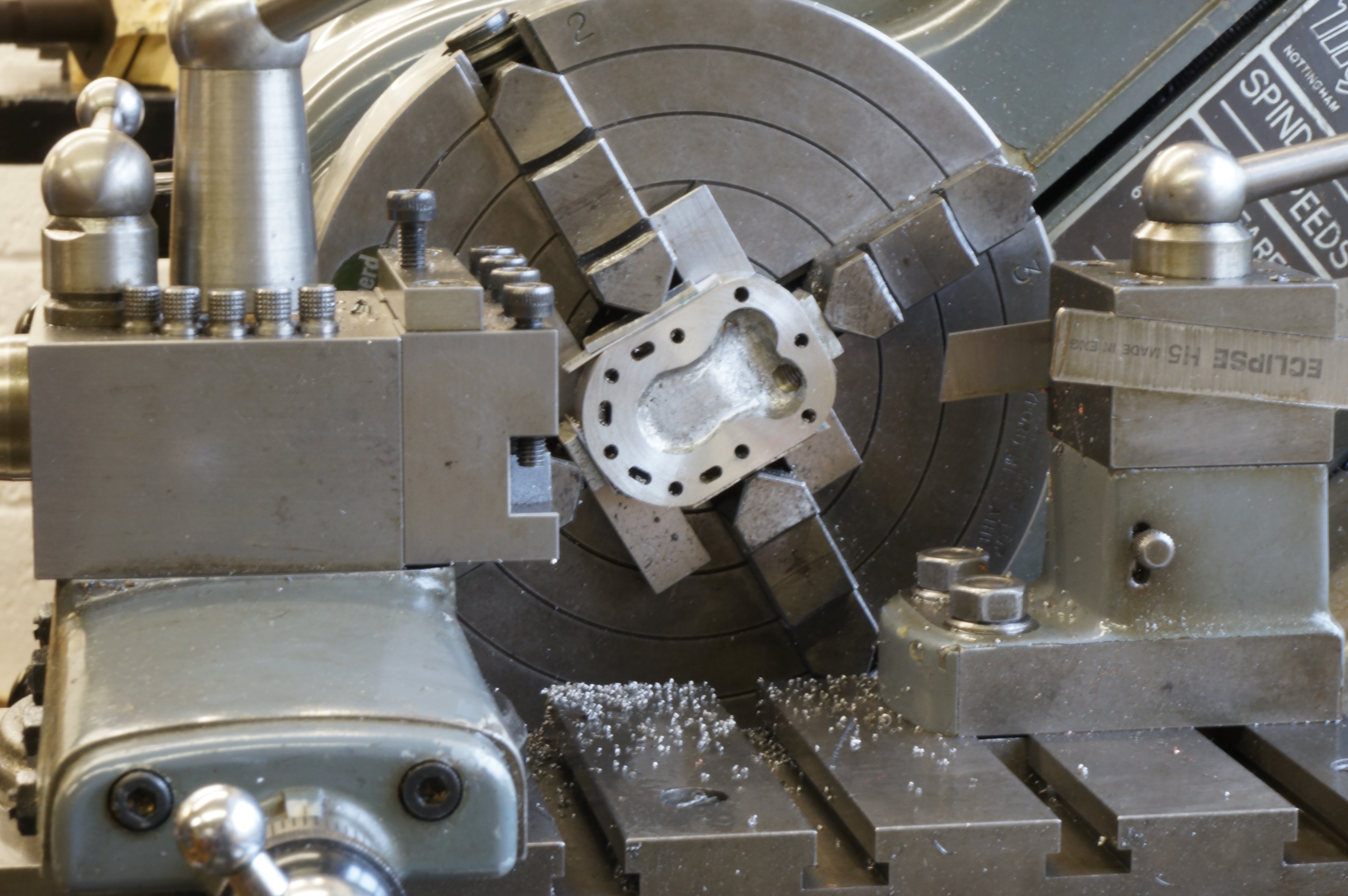
I set up No 2 spare head in the 4-jaw, with aluminium soft packers and card, for facing. This one is the worst of the bunch to machine and has quite deep scoring on the underside face. The target thickness is 0.502″, to allow for lapping, but this dimension is far from critical. This head measures 0.5065–0.5075″. With a freshly honed tool with not much rake and a good radius, I took a 4½ thou cut at 290 rpm, with plenty of RTD liquid. The resulting finish was not bad, but at 0.5008–0.5017″ the height was surprising variable considering the care I took to bed the part against the accurately equal thickness packers. The chamber depth measured about 0.056″.
The other three heads also came out with a thickness variation of up to 1½ thou. It does not actually matter, but I am pretty sure I will try to get them parallel at the final lapping.
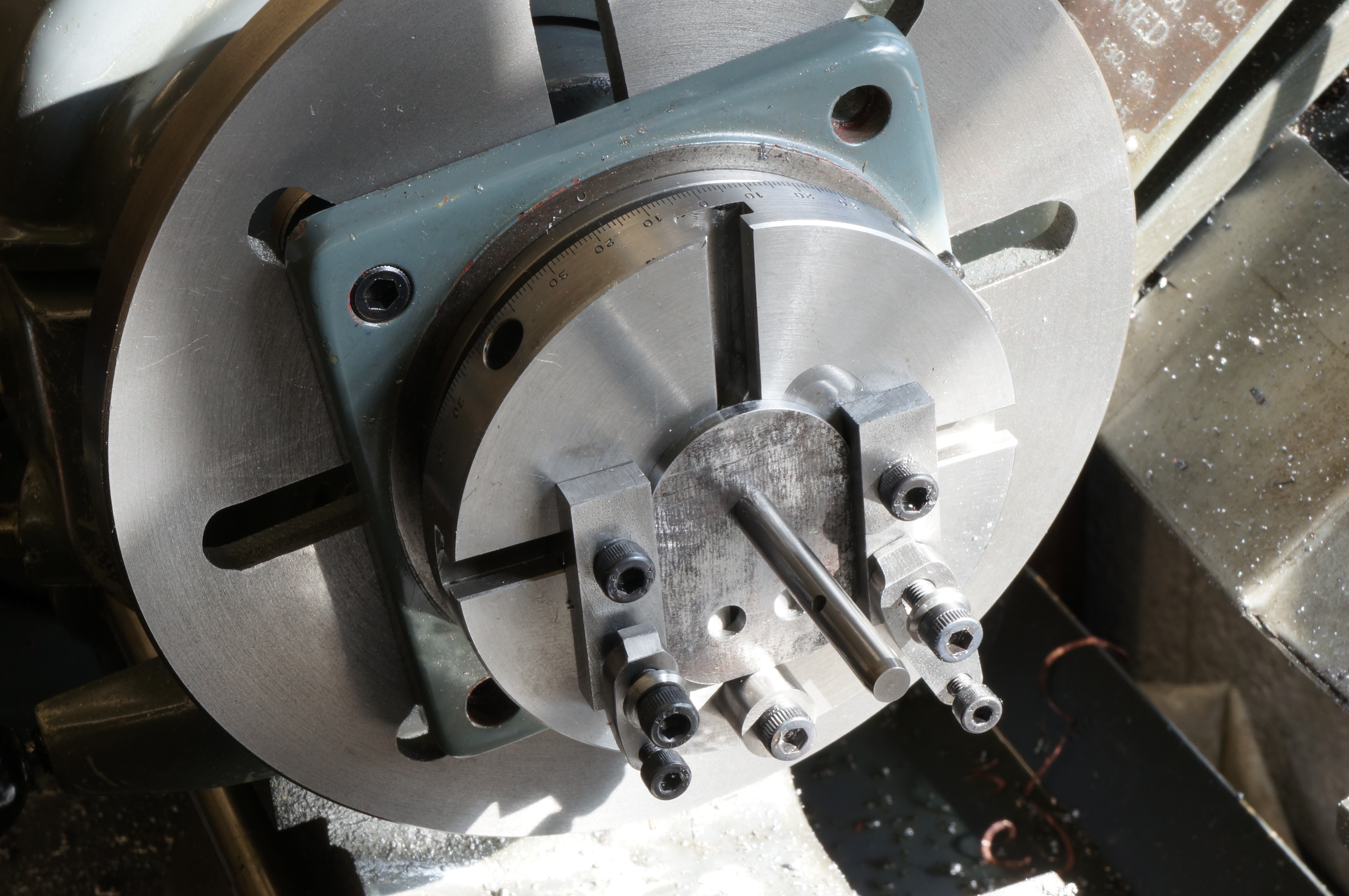
Next, I started to set up for clearing out the combustion chamber radius. I had realised that by mounting the small rotary table as a faceplate, on the faceplate proper, I could use much the same setup as used earlier for machining the profile radius. This bizarre arrangement proved to be pretty easy to set up, and most effective. (3½ hours)
2015-03-04 - Finishing the combustion chambers
At first I tried an existing 1⁄8″ radius tool, but it did not have enough clearance for an internal cut, so I ground one up for the job, with a 5⁄32″ radius. It had to be set up with a lot of overhang from the toolholder to clear the clamp bolts. I did the spare heads first, and then the deeper chambers in the main ones.
The heads are now ready for bead blasting. (¾ hours)
.