
Cylinder Liners
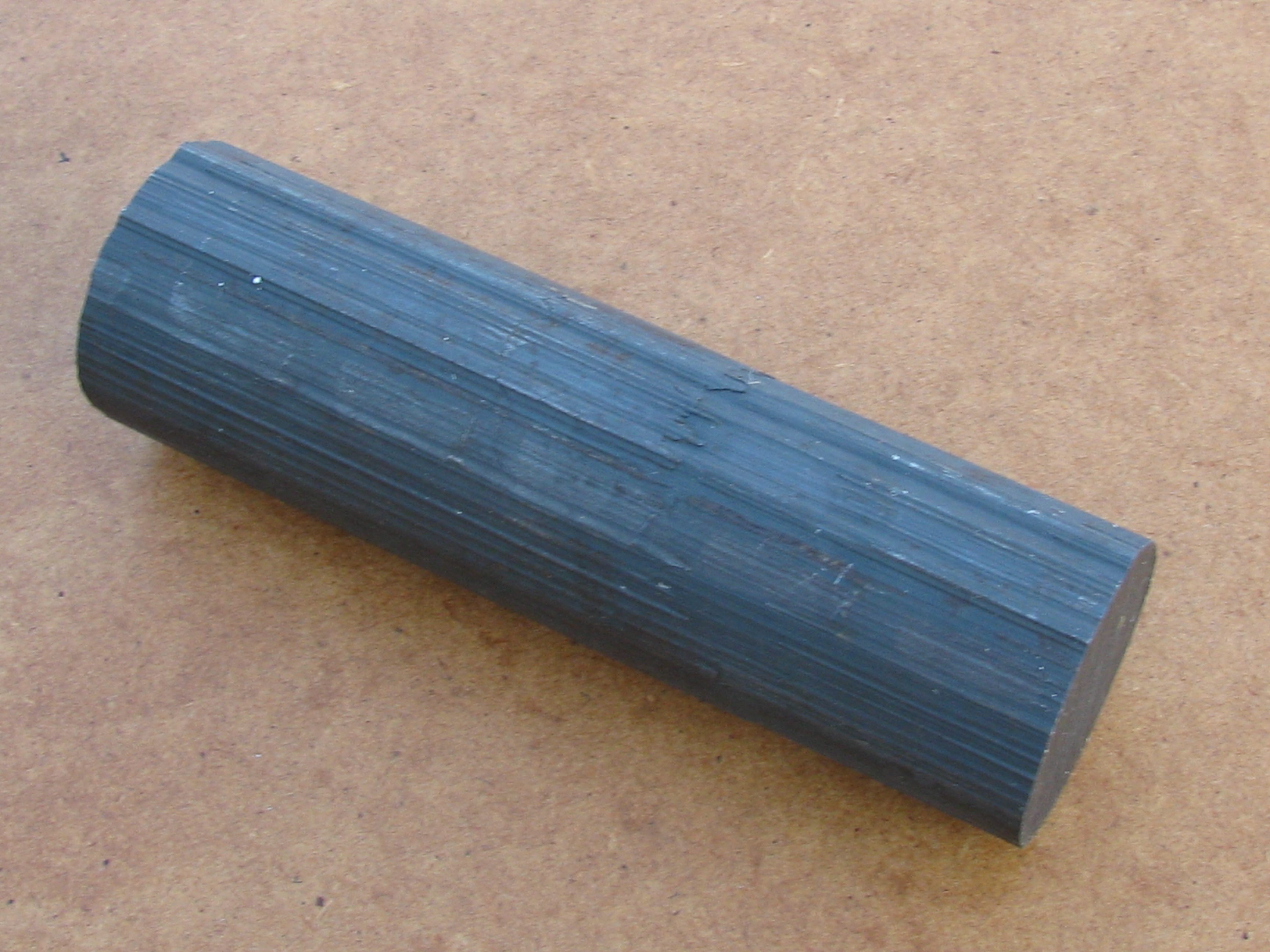
The kit contains a piece of what I think is continuous cast iron bar for the cylinder liners. At 104 mm long and 31 mm diameter, it provides ample length for a chucking piece and enough meat to get well under any hard surface.
I considered trying to get the valve liners out of the same piece, which might be possible, but not easy. In the end I decided to go the easy way. It means the bar can be drilled right through, and that is easier to work with than the tight-for-length blind holes that would have been needed to save enough stock out of the middle for the valve liners.
I decided it would be a good idea to follow the best traditional practice and rough out the liners and then leave the material for some time to stress relieve before finishing. I will not, however, be seasoning this piece out of doors; though I am thinking of a mild heat treatment to help it along.
2012-02-11 - Roughing out

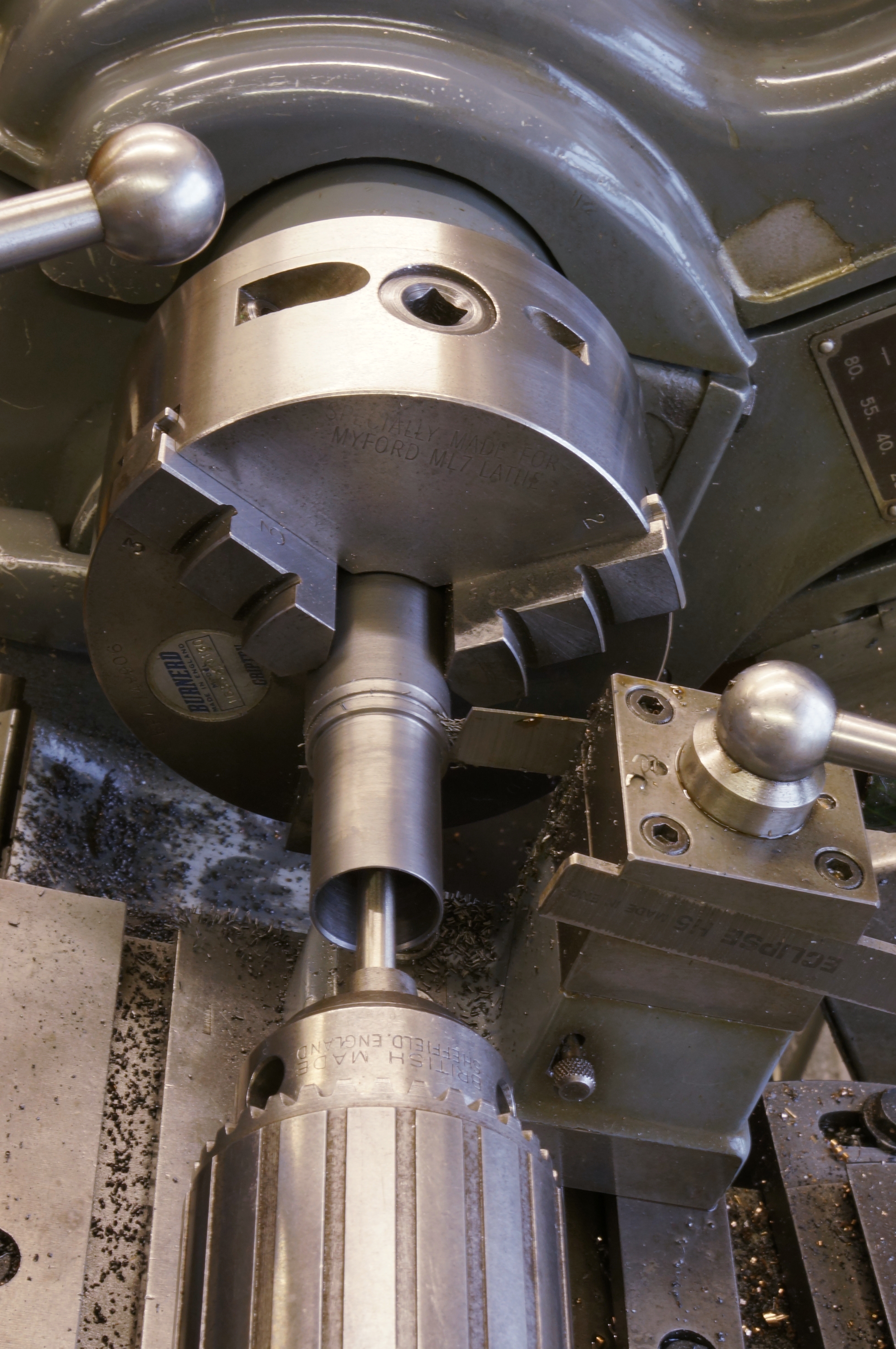
Roughing out was straightforward turning, drilling and boring. For once I will give the speeds, and cut depths. I usually have the feed set fine, at about 0.0012″ and it needs to be a big job for me to bother to change to a coarser pitch for roughing out. Turning and boring were done with carbide insert tools.
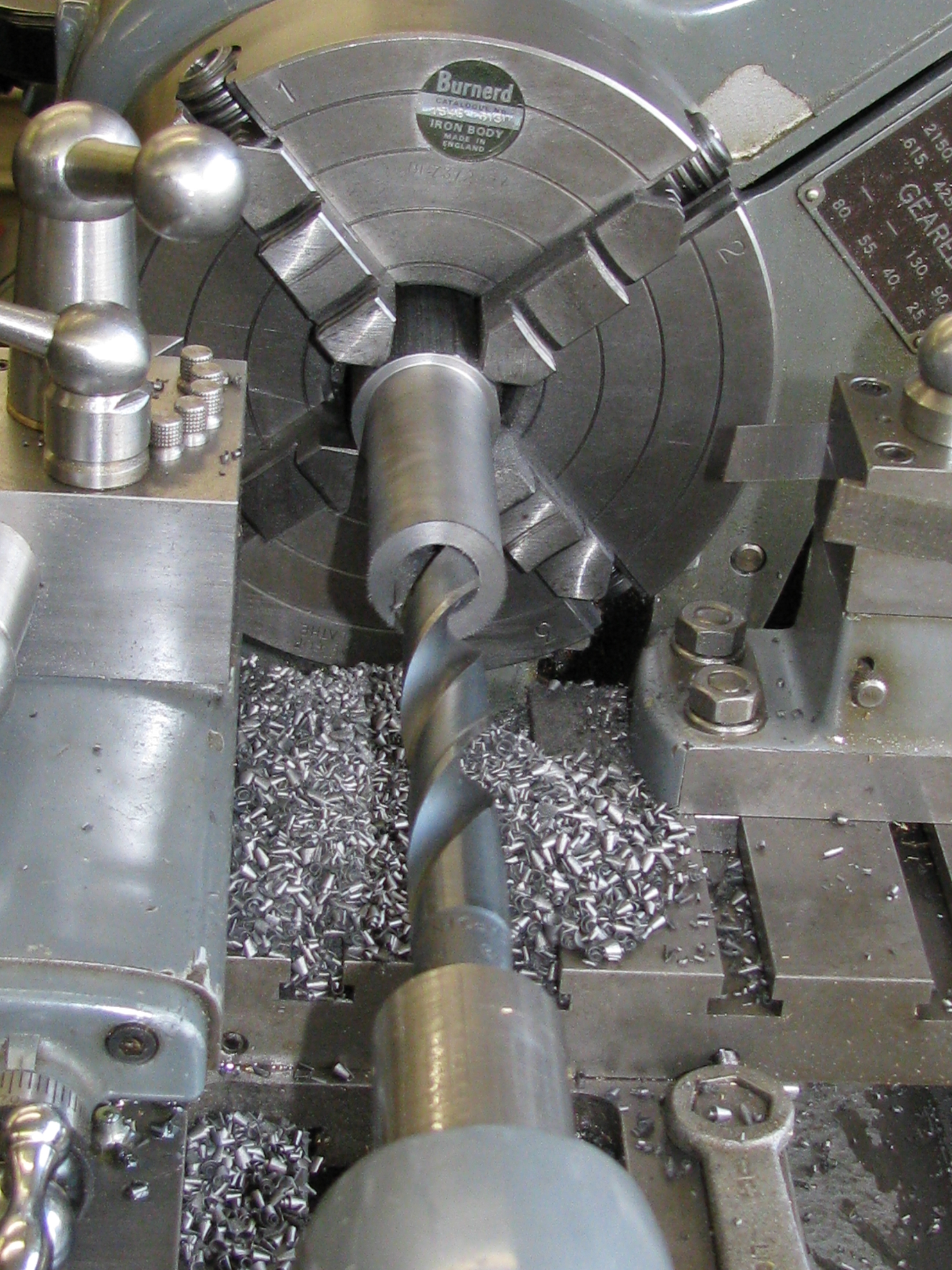
With a minimum projection, the rough bar was adjusted reasonably true in the 4-jaw chuck, during which process I managed to turn it backwards into the tool. Not at all hard, but enough to knock a chip off the carbide tip.
After changing the tip, I took the first cut of about 30 thou at a modest 290 rpm to get through the skin, followed by two cuts about 40 thou deep at 425 rpm to bring the bar to 1″ diameter. I then centred it and drilled half way through with a ¼″ drill at 615 rpm, ½″ at 425, and 5⁄8″ at 290 rpm. I reversed the job in the 4-jaw chuck, clocked it up on the machined OD to within a thou, and dealt with the other end in the same way.
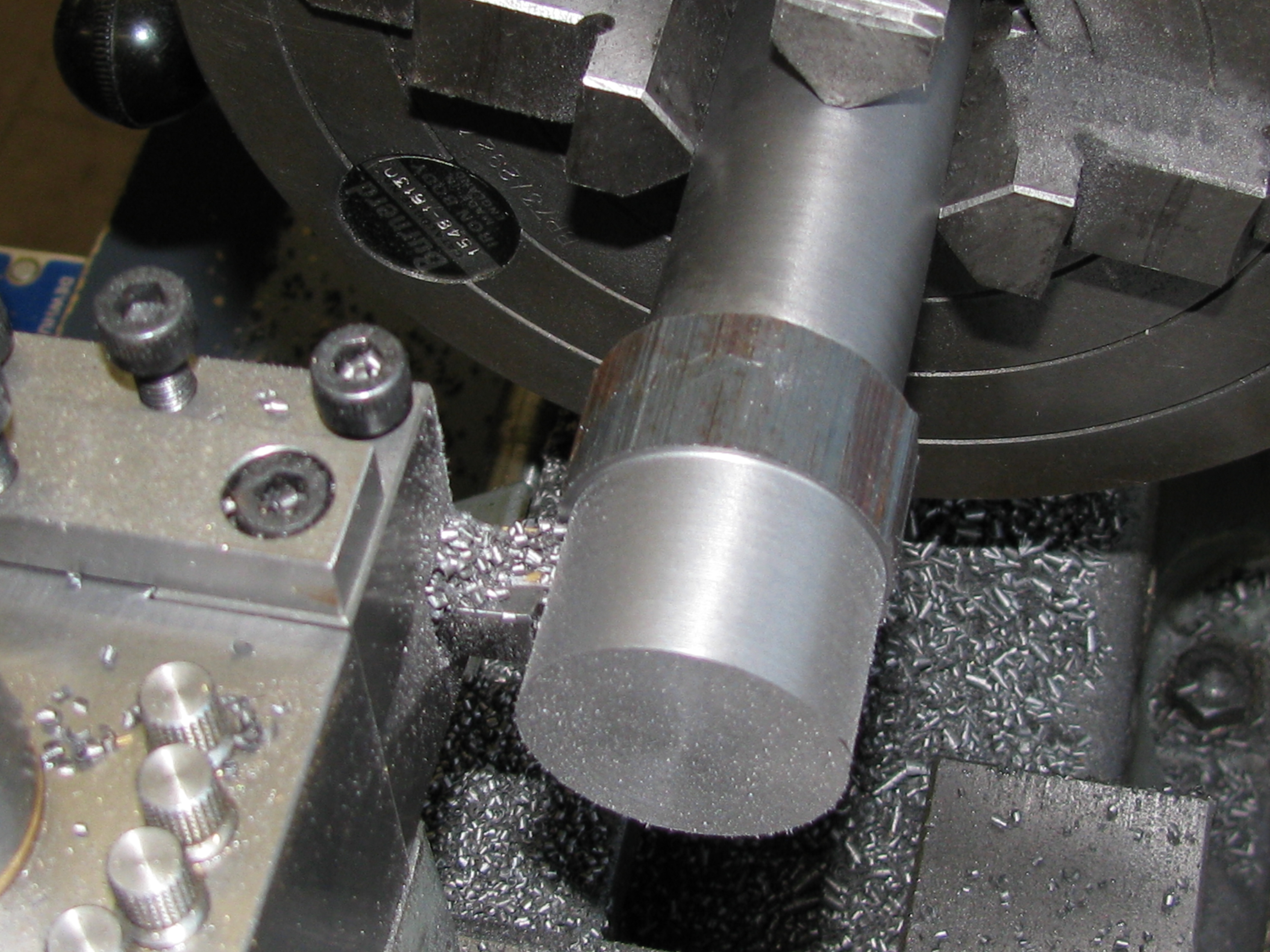
Next, at 615 rpm, I reduced the projecting length with a 15 thou cut to roughly 31⁄32″ and with two 30 thou cuts turned a 1″ long shoulder to 27⁄32″ leaving plenty of gripping length for machining the other end. The bore was opened out to 23⁄32″ with 3 cuts of 15 thou each.
Switching to the more delicate grip of the 3-jaw chuck, I reversed the job again, and bored out in the same way. This time I turned the shoulder to 19⁄32″ long. I took the outer ¼″ of the chucking length down by a couple of thou to avoid a step throwing the chucking out. Finally, I reversed it again and increased the shoulder length to match the other end.
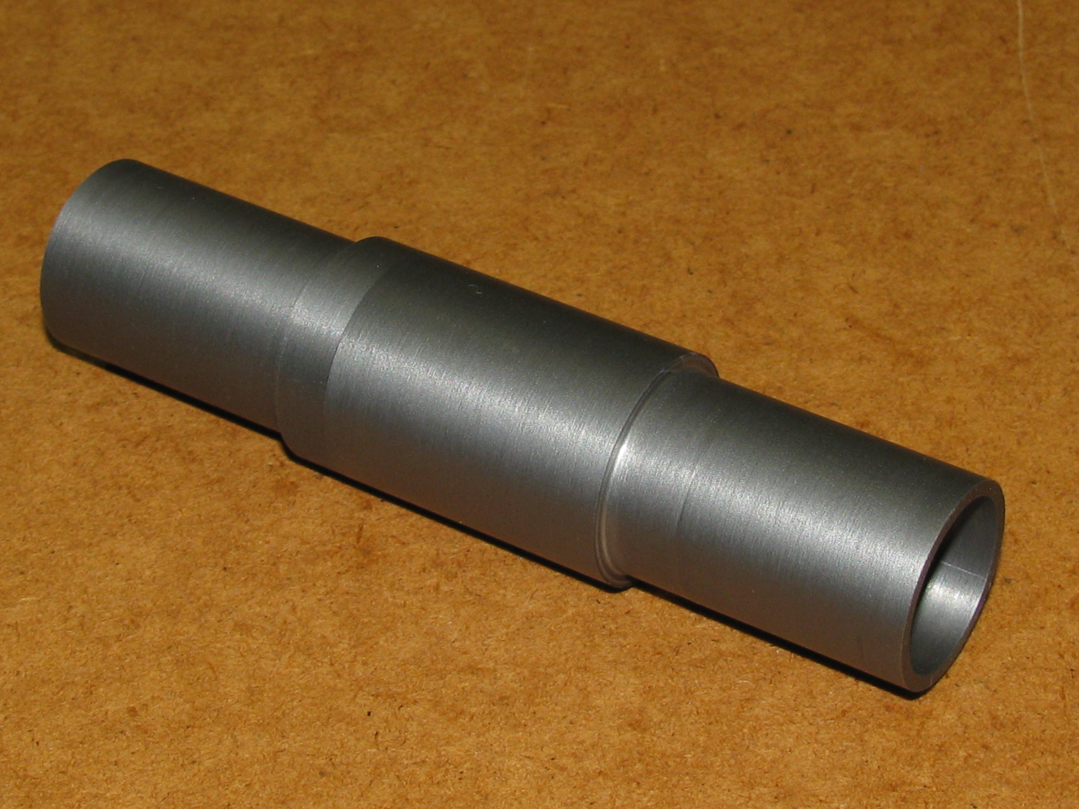
This work leaves all diameters needing 1⁄32″ for finishing the liners, but I will leave it for a month or more before doing any more work on them. (2½ hours)
.
2014-07-19 - Finish Turning
So, rather more than a month then. As more like 2½ years have passed, the iron should be well enough seasoned by now. Looking round for a piece of material to make a gauge for the liner bores, I ended up using a stub of bearing bronze, and turned diameters which came out at 0.7473″ and 0.7488″. The larger diameter should just go in, leaving 0.001″ for lapping.
The cylinders are near enough identical that the liners should be interchangeable, but I decided make the first one to fit No 1 cylinder.
With the job in the 3-jaw, a fresh edge on the carbide tool, and running at 700 rpm, I faced the end and extended the sleeve diameter to just less than the finished 15⁄16″ length and turned the O.D. with successive cuts of 10, 4, 1 & ½ thou to give a diameter of 0.8121″ at the top and 0.8118″ at the bottom. The slight taper goes the right way and it is a perfect easy fit in the cylinder without detectable shake. I turned the shoulder to finished length (by rule with magnification) and turned the shoulder diameter to 0.933″, which is about 0.003″ less than the recess, and less than intended, but it will be OK with the Loctite. I finished the exterior with a 0.004″ chamfer at the bottom and an 0.008″ one on the corner of the shoulder, and checked that it goes fully home in the cylinder.
Again with the tip in the large boring bar turned to a fresh edge, I took 10 thou off the bore, which then felt pretty well parallel at 0.731″. After further cuts of 6 thou to 0.743″ and 2 thou to 0.747″ the gauge would not enter. I reversed the feed and took an outward cut at the same setting, giving a bore of 0.748″ that the first step of the gauge would fit with a little bit of shake. Returning to normal feed direction I took a half-thou cut at the same setting, which just scraped, taking nothing measurable off. Another half-thou took the bore to 0.7485″. With another cut of a couple of tenths the second gauge diameter would enter, and the bore measured 0.749″ - just right for lapping.
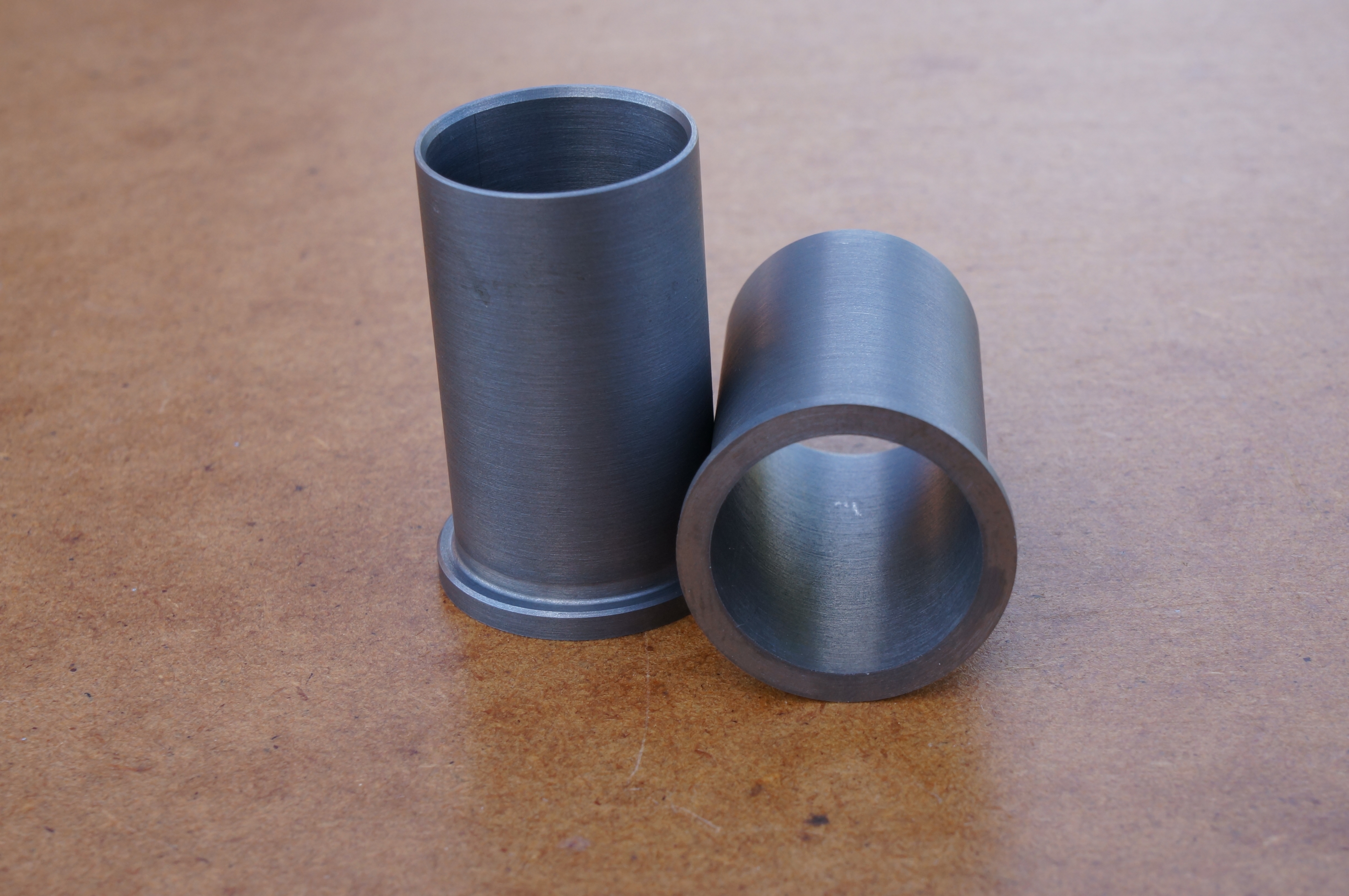
There is a shallow chamfer at the bottom of the bore to aid fitting over the piston rings. I intended to make this at 25° but miscalculated the indexing of the toolpost and cut it to depth at 37½° instead, leaving the bottom edge a bit thin and fragile. I decided to have lunch while I thought about whether to cut back a bit and do it again. With plenty of metal available I decided to get it right. I faced about 20 thou off the bottom end and re-cut the chamfer, then re-cut the shoulder at the top to length. I then parted off the liner, leaving about 15 thou on top for final facing after assembly.
With the stock reversed, I turned and bored the second liner in the same way. With the O.D. on size at the bottom end and +0.0002″ at the top the cylinder would go but was too tight to risk trying to go all the way. I put on a ¼ thou cut, which irritatingly took 1½ thou off the diameter so that it measured 0.8110″ at the bottom and 0.8112 at the top. This fits the cylinder casting with just detectable shake. It is a fraction smaller than I would have liked, but is still a good fit for Loctite. The rebate for the liner flange in No 2 cylinder measures 0.938″, and at 0.936″ the shoulder on the liner fits nicely.
Boring also went very much along the lines of No 1. Again, I made the existing bore deeper, and starting from 0.716″, cuts were 10 thou to 0.730″, 5 thou to 0.7395″, 3 thou to 0.7459, and 1 thou to 0.7482″. The first diameter of the gauge went in easily. With a further cut of nominally ¼ thou, I measured the bore at 0.7490″ and the second diameter on the gauge just screws in part way. Excellent. With the internal chamfer cut ( at the correct angle this time) I parted off the No 2 liner.
As it turns out, the liners are indeed interchangeable, but fit slightly better as assigned. The next job will be to make a lap to finish the bores. (4 hours)
2014-12-20 - Assembly
With the lap completed earlier in the day, I was ready to fix the liners in place. I washed the cylinders in hot water and detergent and cleaned the liners with Loctite 7063 then gave them a thin coating of Loctite 648 high temperature retainer. After assembly and cleaning up the excess, I put the cylinders by the shop heater to cure.
Later, I took a quick trial cut on No 1 cylinder. (1 hour)
2014-12-26 - Lapping
After some more lapping of both bores, I soon decided that I needed a gauge. I turned the remaining length of the bronze gauge to 0.7498″. After a bit more work the gauge goes almost full depth into the bottom of a carefully cleaned No 1 bore, and a little way into the top. On No 2 it goes ¼″ into the bottom, and will not go in the top. I continued working the tight spots until the oiled gauge would push smoothly through both bores, but would not drop through under gravity. Lapping throughout I used fine valve grinding paste, which has produced a fine, even, matt surface which I think will hold a bit of oil (when cleaned with acetone it dries much paler than when oiled). That's it for the liners, apart from final facing and lapping the top face of the cylinder assembly, but that has to wait until the valve guides have also been fitted. (2½ hours)
.