
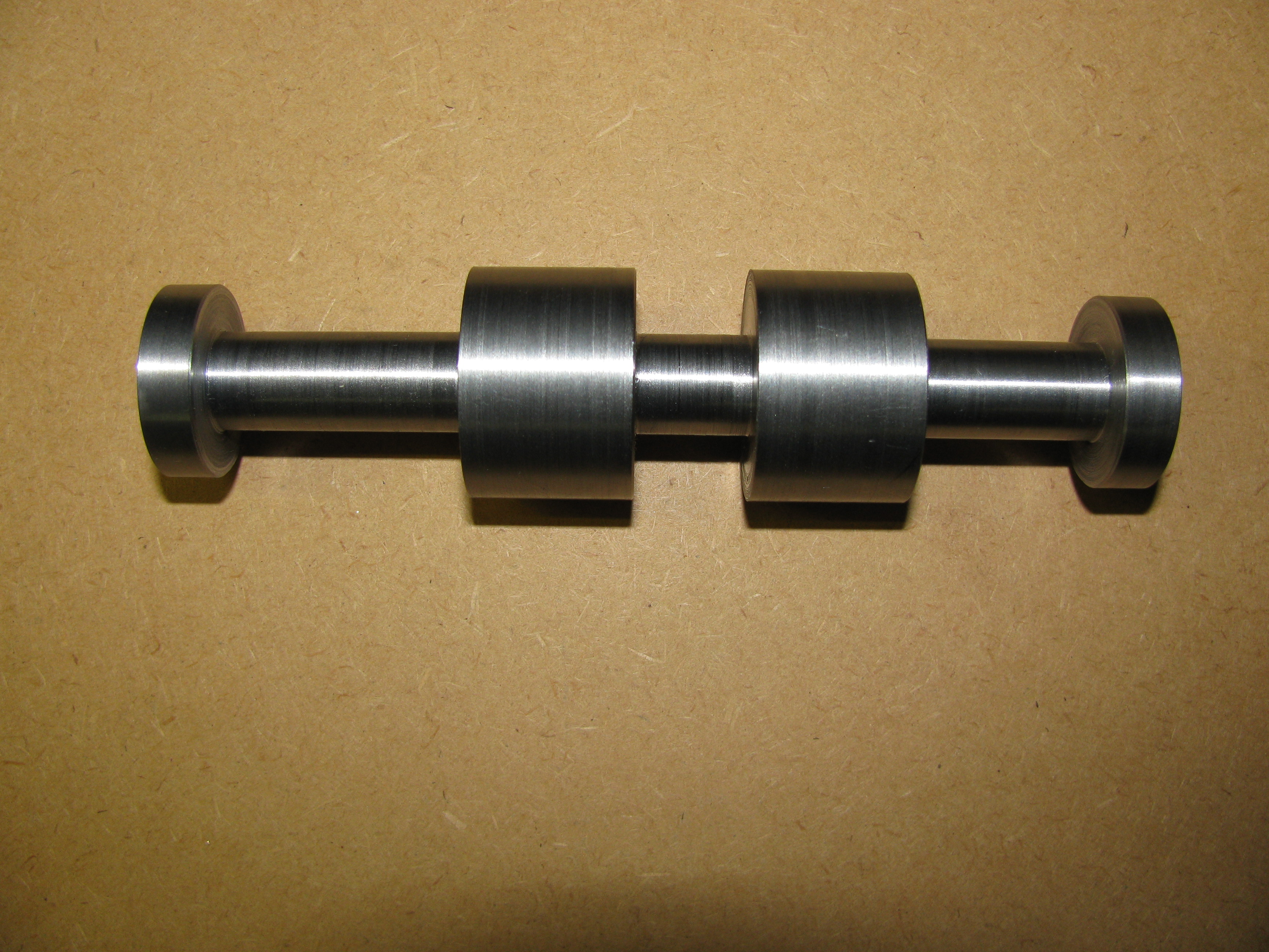
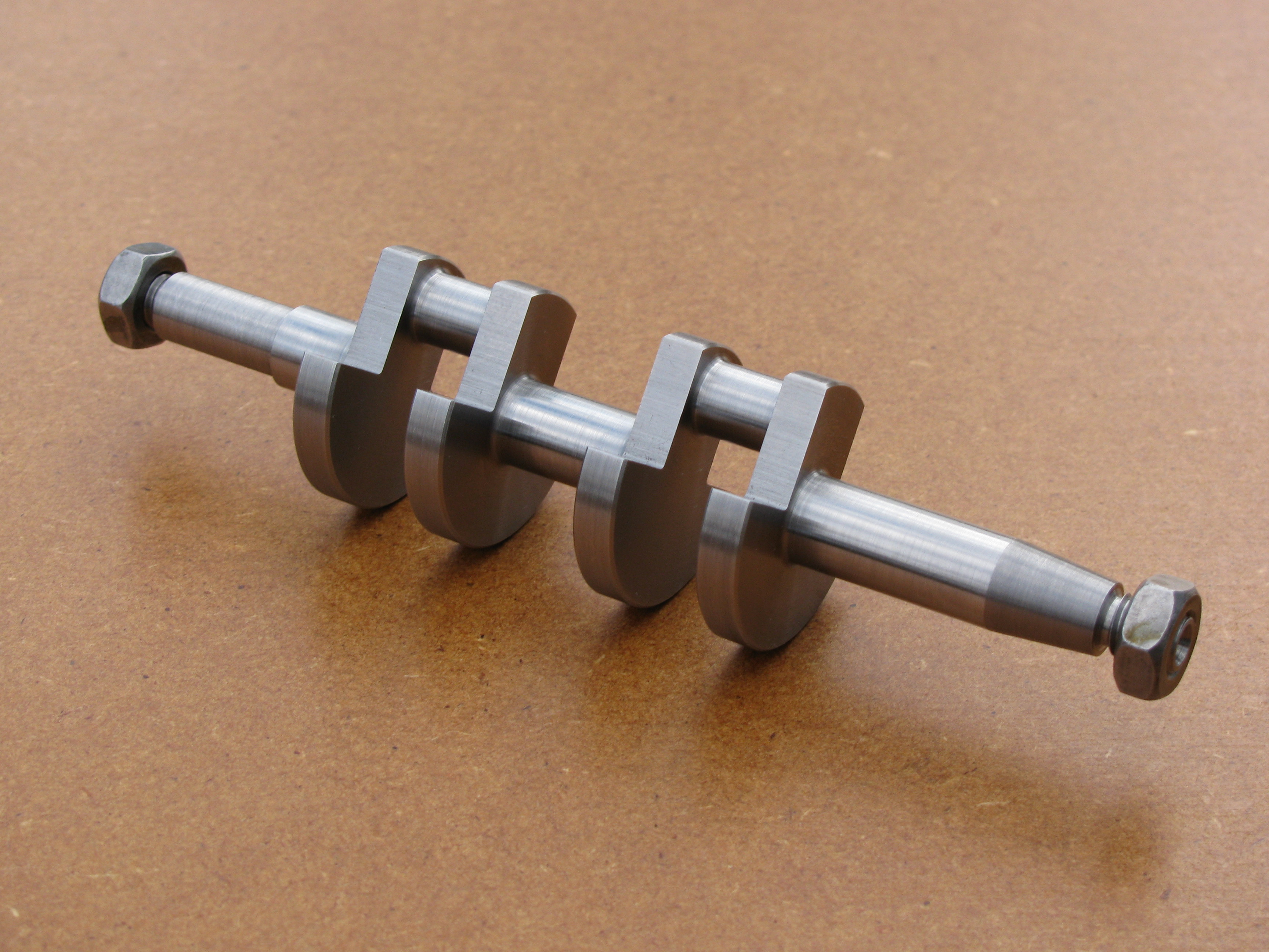
Crankshaft
I decided to start with the crankshaft, as I expected it to be a long and tricky job. I have made no changes from the drawings, but I am using a conventional feather key to drive the timing pinion.
Balancing
Much later, as the engine approached completion, and after I had started using 3D CAD, I used its facility for automatically calculating mass and centre of gravity to explore the question of balance. In my ignorance, I expected the built-in balance weights to be excessive. Not so, it seems. In fact, even with aluminium alloy pistons and con-rods, it turns out that it would be necessary to add weights at least 0.04″ thick to both sides of each web to achieve the usual amount of balance. With cast iron pistons or gunmetal rods it would be a whole lot more. However, I am not going to change anything at this late stage.
2010-01-12 - Parting off and facing
In parting the spare inch off the bar, I managed to snap a 1⁄16″ parting blade. I don't think that has happened since I built the rear parting toolpost in the 1970's. An auspicious start to the project. The ends were faced leaving just a few thou over the final size. (1½ hours)
2010-01-13 - Centre drilling
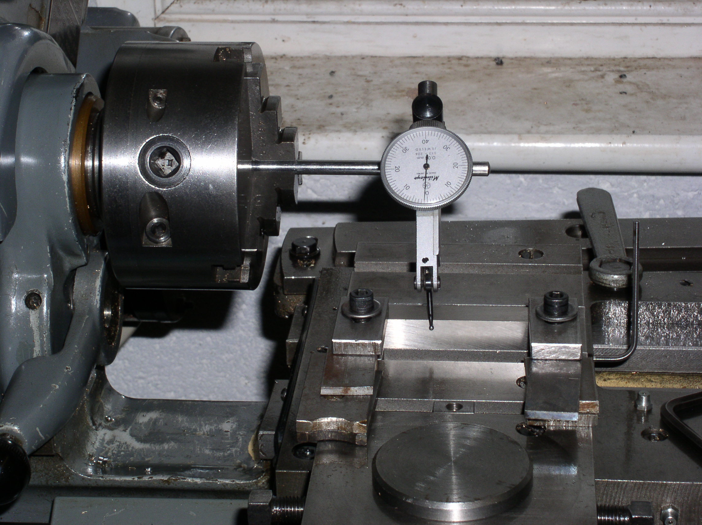
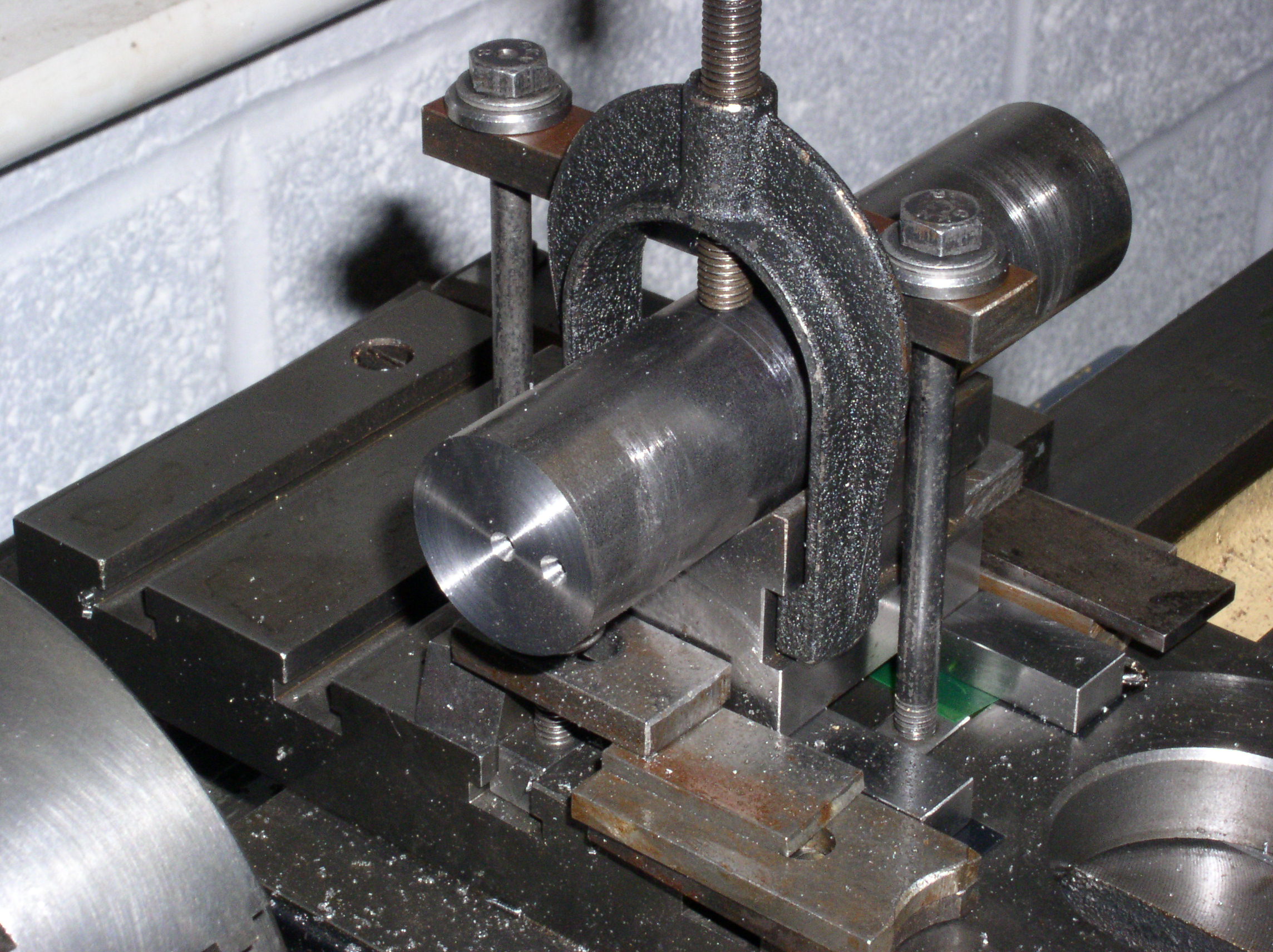
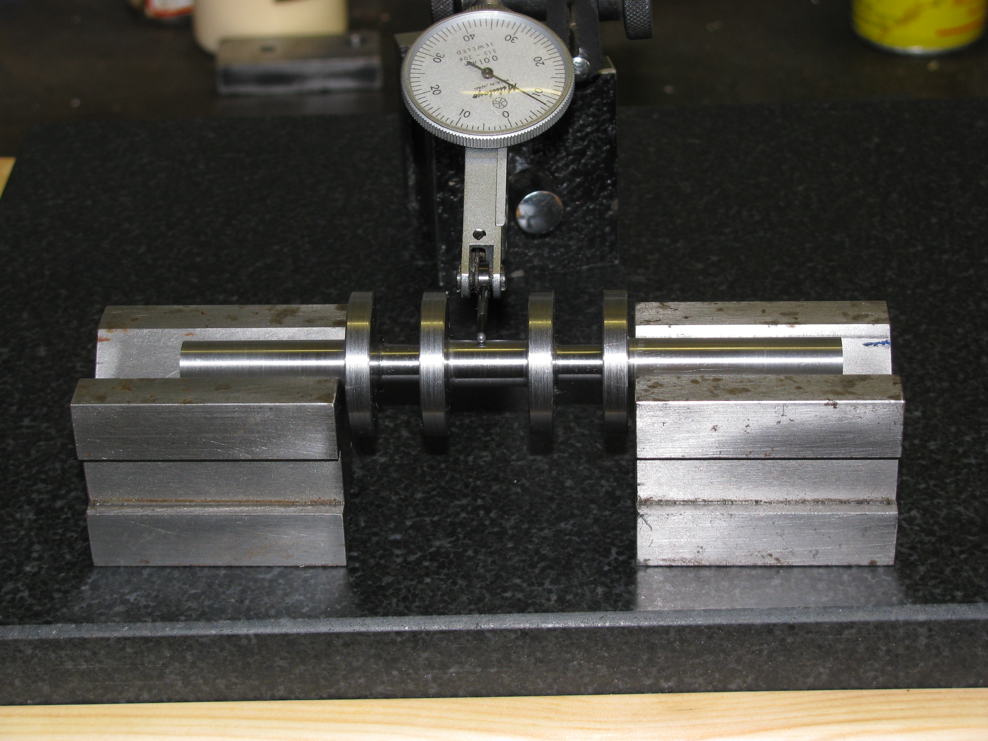
Rather than rely on my erratic marking out, I used the boring table to set out and drill the centre holes accurately and so get the crank throws spot on.
A guide bar (a ½″ square tool bit in my case) was clocked up across the width of the boring table.
The shaft was clamped to a vee-block in a position that would allow a bar clamp over it too. The saddle clamp remained in position until all the centres had been drilled. This is how I ensured that all the centres lie in a plane. With one side resting against the guide bar and a strap over the top, the vee-block was packed and shimmed up to centre height by trial and error using a clock in the chuck for a 'turn-around' test on the end of the bar. This is where a small mirror comes in very handy for reading the upside-down clock. The bar does not need to be dead centre for height, a couple of thou off would be OK, but there is no excuse for not getting it cock-on front to back using the cross-slide.
With a DRO on the cross-slide the next bit would have been easy. I don't have one. I could have relied on the cross-slide dial, but I decided to do it by the old-fashioned jig-borer's method of using an ARO - (Analogue Read Out). A dial gauge is mounted on the cross-slide to contact a suitable surface mounted on the saddle and slip gauges are used to set the distances involved, bringing the dial to zero in each case so that the measurement is made with the slips, not the DTI. I used a 'sticky block' set square on the saddle for datum. With the bar centred as described, the dial bezel was zeroed, and a journal centre carefully peck drilled — a broken centre drill being best avoided at this point.
I made up a set of slip gauges to 0.3438″ and attached it to the datum face and moved the saddle out 3 turns and nearly a half, to re-zero the dial. Now the crankpin throw centre hole could be drilled. Just a touch of the drill on the bar first, and double checking with a rule that the centre distance seemed correct.
Next, I took the strap off, and with the bar still clamped in the vee-block, turned it end for end, and held it against the guide bar while tightening the strap again. I clocked it up again to centre it front to back and checked for height. If the height had been much out, it would have suggested that the vee-block was not true (or I was not being careful enough over cleanliness). Leaving the slips in place, I set the DTI bezel to zero and drilled the centre hole. Next I removed the slips and wound in the slide to reset the DTI. Finally I drilled the second crankpin centre.
Job's a good 'un (if weird). (3 hours)
.
2010-01-16 - Tool grinding
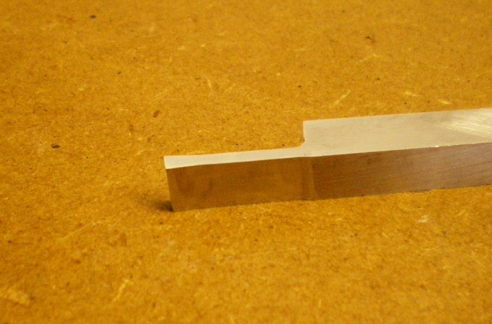
I made up a tool for machining the crankpins with a business end radiused on both sides and a relived shank behind. I took care to reduce the chances of the tool breaking by making the sides and shoulders fairly smooth, rounding the edges and polishing the top face and edges. (2 hours)
2010-01-19 - Tool grinding and roughing out
I made left and right hand knife tools for machining the journals and sides of the webs.
I roughed out the outside diameter, and the journals to just over ½″ and leaving the throw pieces at the ends about 1″, and about 1⁄32″ on the faces of the webs. I found the best way to get the bulk of the material out was with a sharp cornered grooving tool, about 3⁄32″ wide, taking two passes of successive slightly overlapping cuts about 150 thou deep, which was as much as the shoulder of the grooving tool would allow. The approach to this very much depends on what tool you find likes the material. This grooving tool had no rake, and the right and left knives have quite a bit, and did not seem to cut all that well, so that may be a clue. The rings formed at the end of sliding cuts were quite tough to break, suggesting that the material supplied is good stuff. I think it may need machining very slowly to get a good finish. (5 hours)
.
2010-01-20 - A start on the crankpins

The shaft has now been set up between the throw centres and a first 150 thou deep bite taken over a 5⁄16″ width on each pin.
Started grinding up a longer and deeper grooving tool on a 5⁄16″ bit. This is intended for roughing the pins almost to full depth. (2 hours)
2010-01-22 - Crankpins emerge
Finished grinding the deep grooving tool. To get a smooth top surface on this, the fine diamond stone did a good job where an oilstone was too coarse and an Arkansas stone too fine.
Once this was right I continued to rough out the crankpins. It took 2 bites 0.2″ deep, and a final one of .15″ to just clean up the pins all round to a diameter of about 15⁄32″.
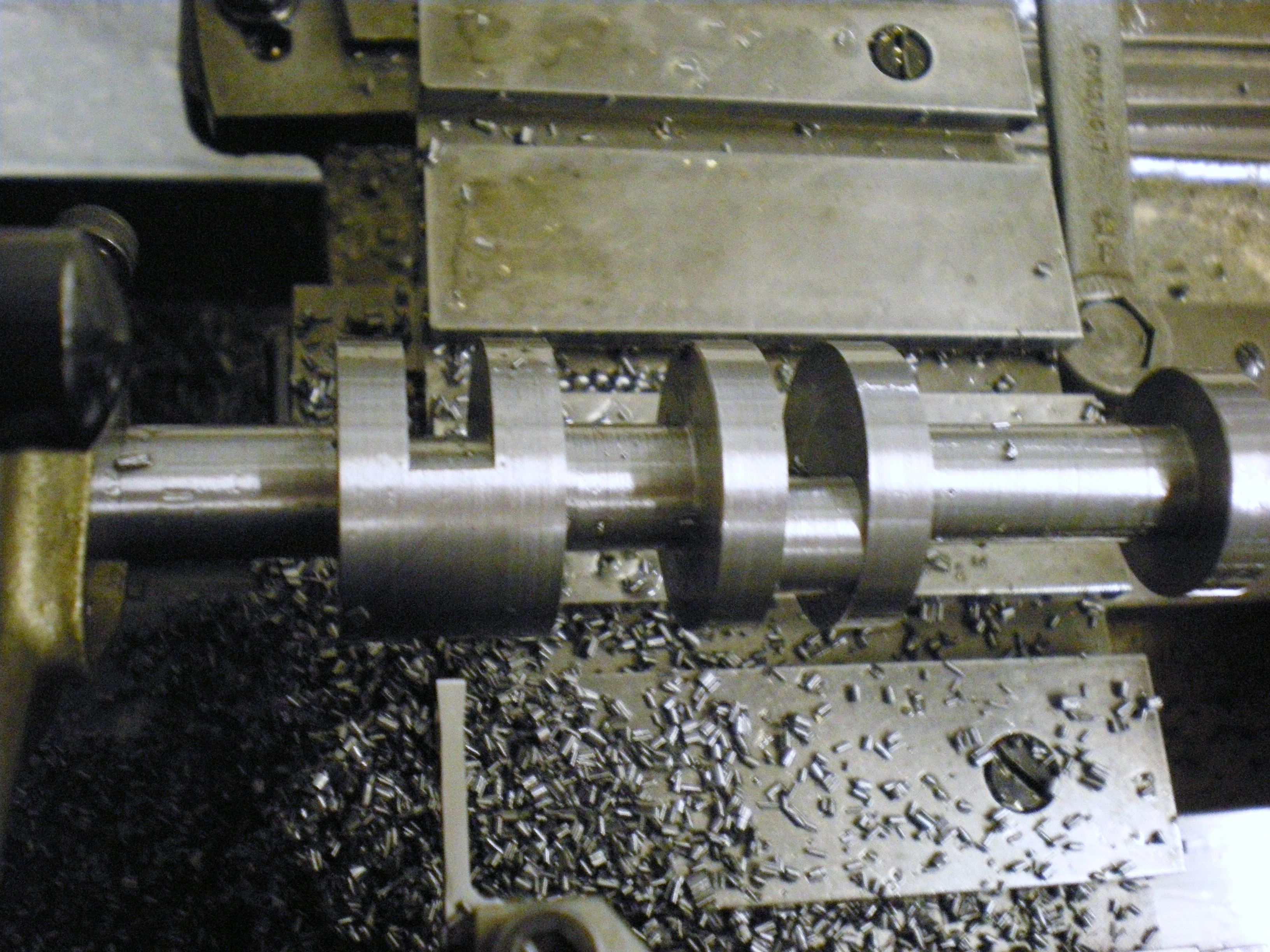
The only slight problem was that the long slender tool was deflecting sideways a little, resulting in the gap between the webs being something like 5 thou smaller by the pins than at the start of the cut.
At this stage the centre of the shaft showed a run-out of 11 thou, the webs opening out. (3½ hours)
2010-01-23 - First approximation
I used the radiused reach tool today to true up the runnout of the journals and the outside flanks of the crank-webs. This tool seems to cut very nicely, but I need to remember to ensure that the flat end is set dead square. I also need to do a check that the lathe is turning parallel. Once this was done, I took a set of length measurements to find out how much more needed to be removed from each crank-web. The outsides of the crank-webs were machined to ten thou oversize.

Started working on thinning the inside faces of the crank-webs to plus ten thou. At this point the lathe was in back-gear and the spindle pulley decided to seize on the shaft. As the web was nearly done, I finished it in bottom open speed. Then I stripped down the spindle, polished off the narrow ring of picked-up bronze, rubbed away the ridge in pulley bush and put it back together. It seems to be working fine now, but another good session will be needed to make sure. (4½ hours)
.
2010-01-30 - Second Stage
The inside faces of the other three webs were machined to +.010″. I found that the radius tool was deflecting, and, on the number 1 crankpin, took a backing-out shave as well. The crankpins were reduced to 3⁄8″ at the same time. These cuts were done at 80 rpm. At this stage the centre journal was showing 0.001″ runout.
The journals were then reduced to 7⁄16″ diameter, machining at 200 rpm, which gave a bit of a squeak, but there is no chatter visible to the naked eye. Another check on runout gave crankpin 1: 1¼ thou, crankpin 2: 2½ thou, centre journal: 1½ thou. After a bit of head scratching I found that the centre journal TIR could be reduced to within half a thou by minor alteration of the pressure of the tailstock centre. Clearly I have been flexing the shaft, and will need much lighter pressure for future cuts - just enough to drive the revolving centre. It also highlights the need for spacers between the webs when finishing the journals.
To be on the safe side, I decided on a gentle stress relieving. The oven was put on full blast for an hour, which turned the shaft a nice shade of blue as well as the air, in more ways than one. I think it was getting well up to the claimed 300° limit of the oven. After cooling, and under the lightest pressure this time, it showed .003″ TIR at the centre journal, .001″ at crankpin 1, and about 2 tenths at journal 2, so it has not moved much, which is most gratifying, and there was no further movement during the following week. (3¼ hours)
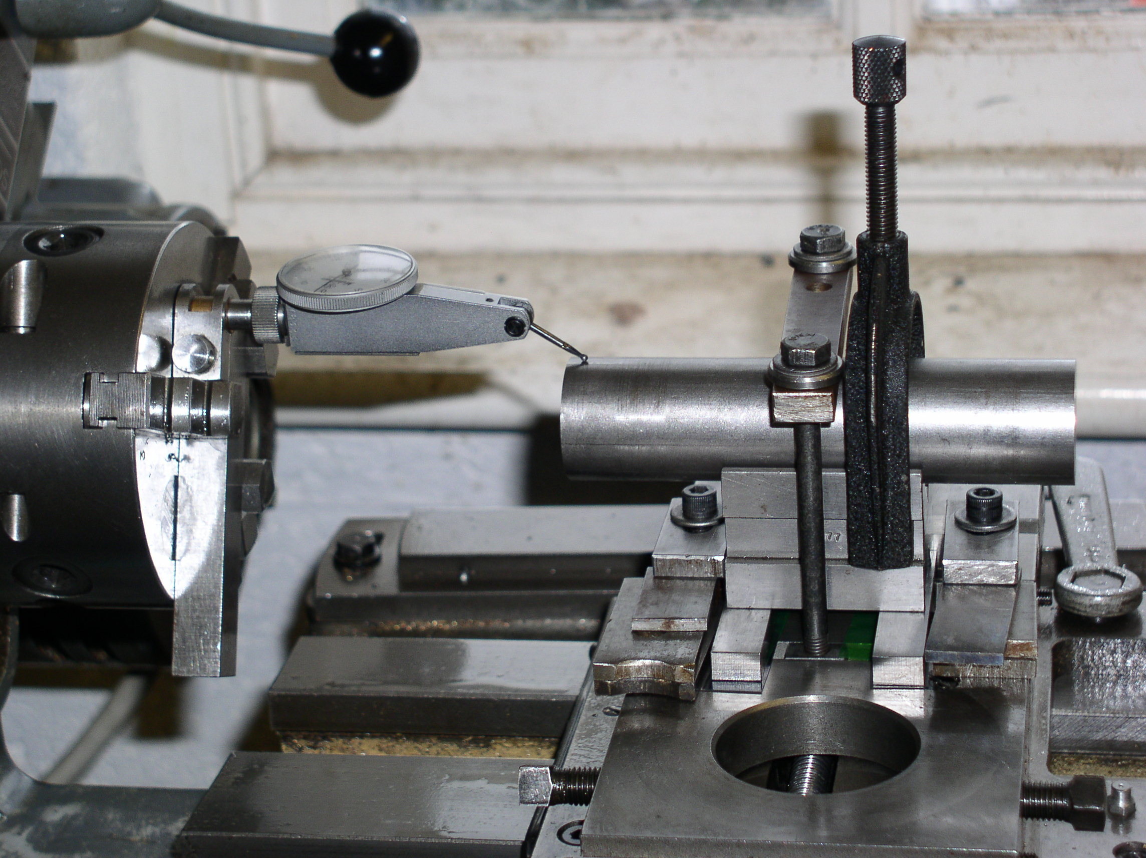
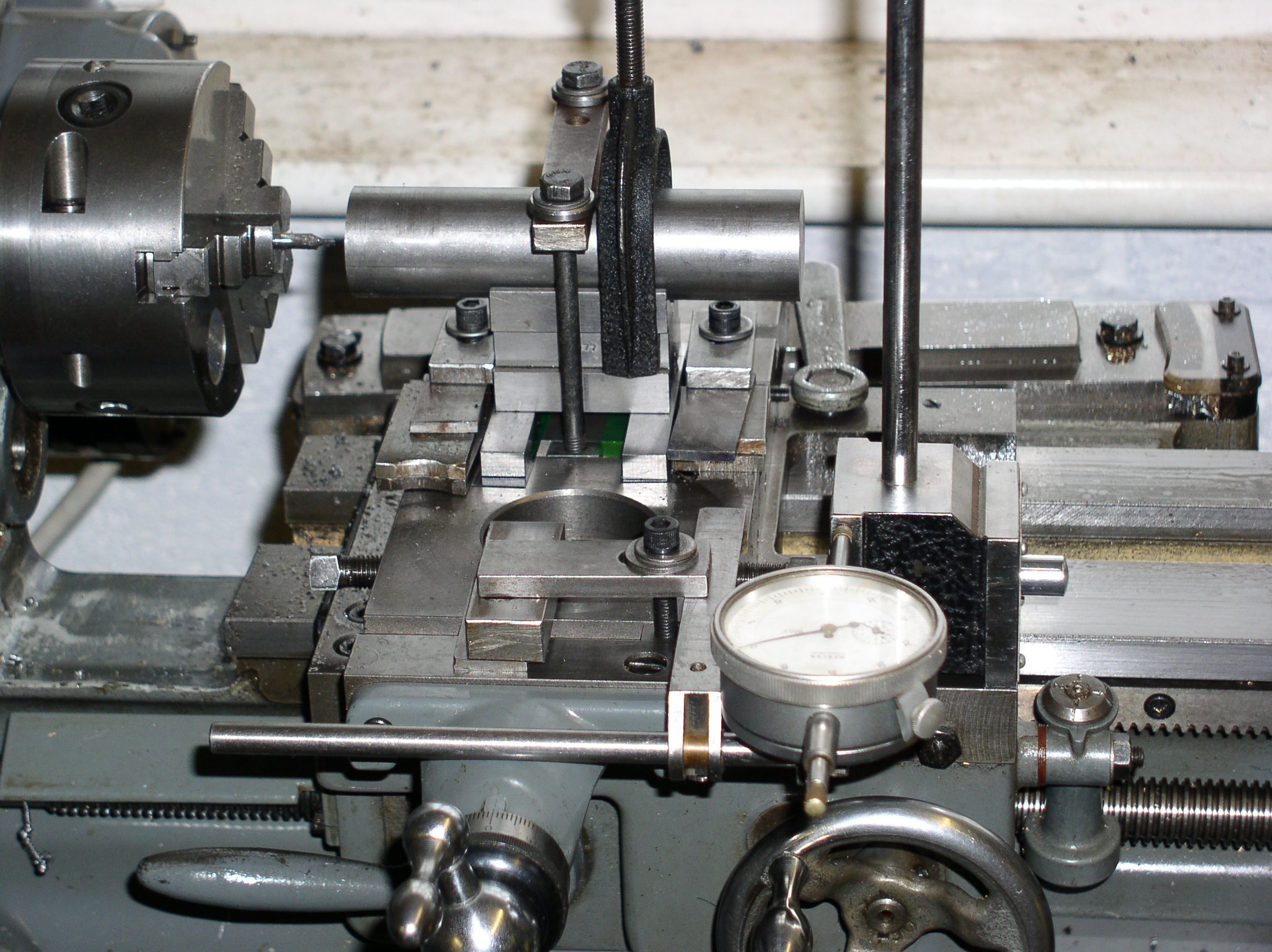
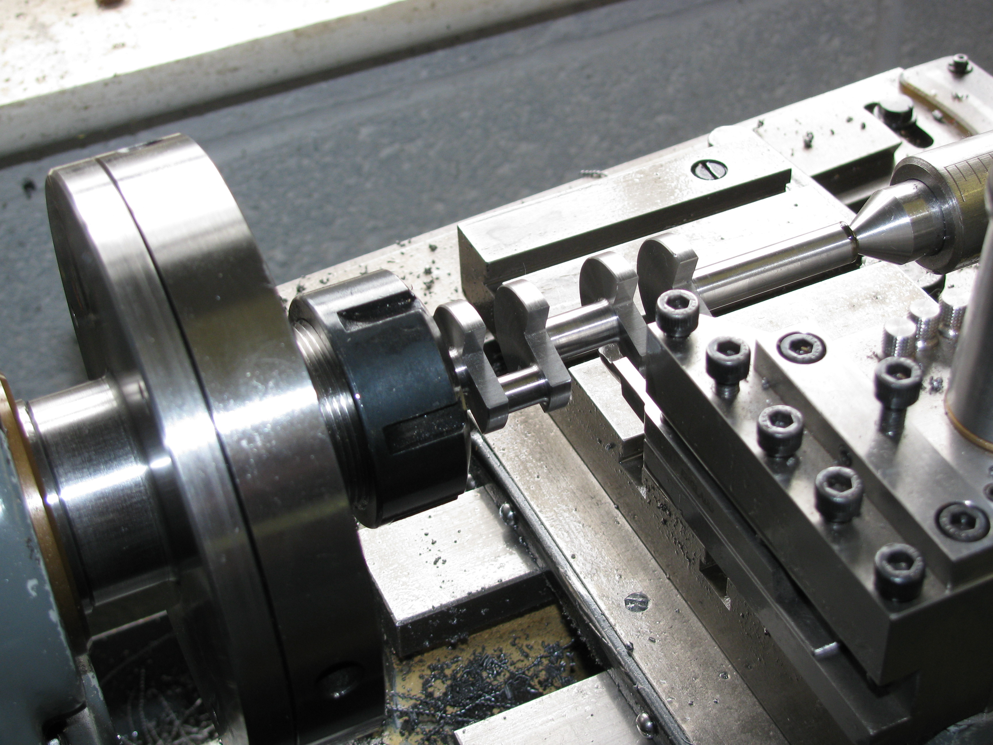
2010-02-05 - Setting up web cut-outs
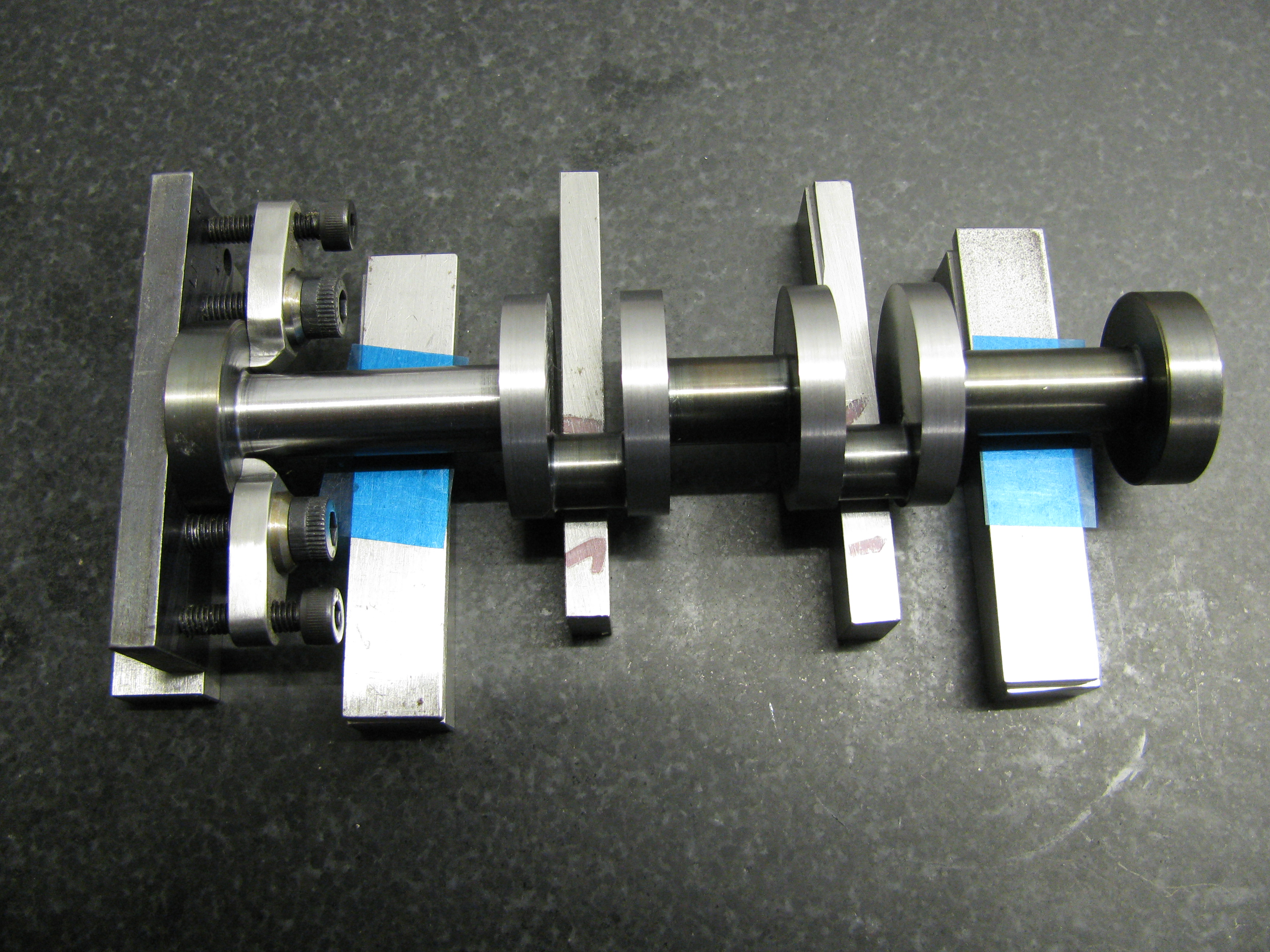
I decided to make the web cut-outs for forming the balance weights at this stage, in case this caused any distortion. The outside diameter of the webs was turned down to 1.130″. I then spent the rest of the afternoon coming up with a scheme for holding the shaft square on for milling. I set it on parallel packing on the surface plate so that the two axes were exactly the same height, and clamped a plate on one end as an alignment datum. This seemed much more accurate than relying on a scribed line about one inch long. For the machining setup I initially thought of clamping to a vertical slide arranged much as it is on the surface plate, but I have no clamps small enough to fit between the crank-webs, and there was no room to get clamp bolts in either, so it will be set up in the machine vice. (2½ hours)
2010-02-06 - Forming the weights
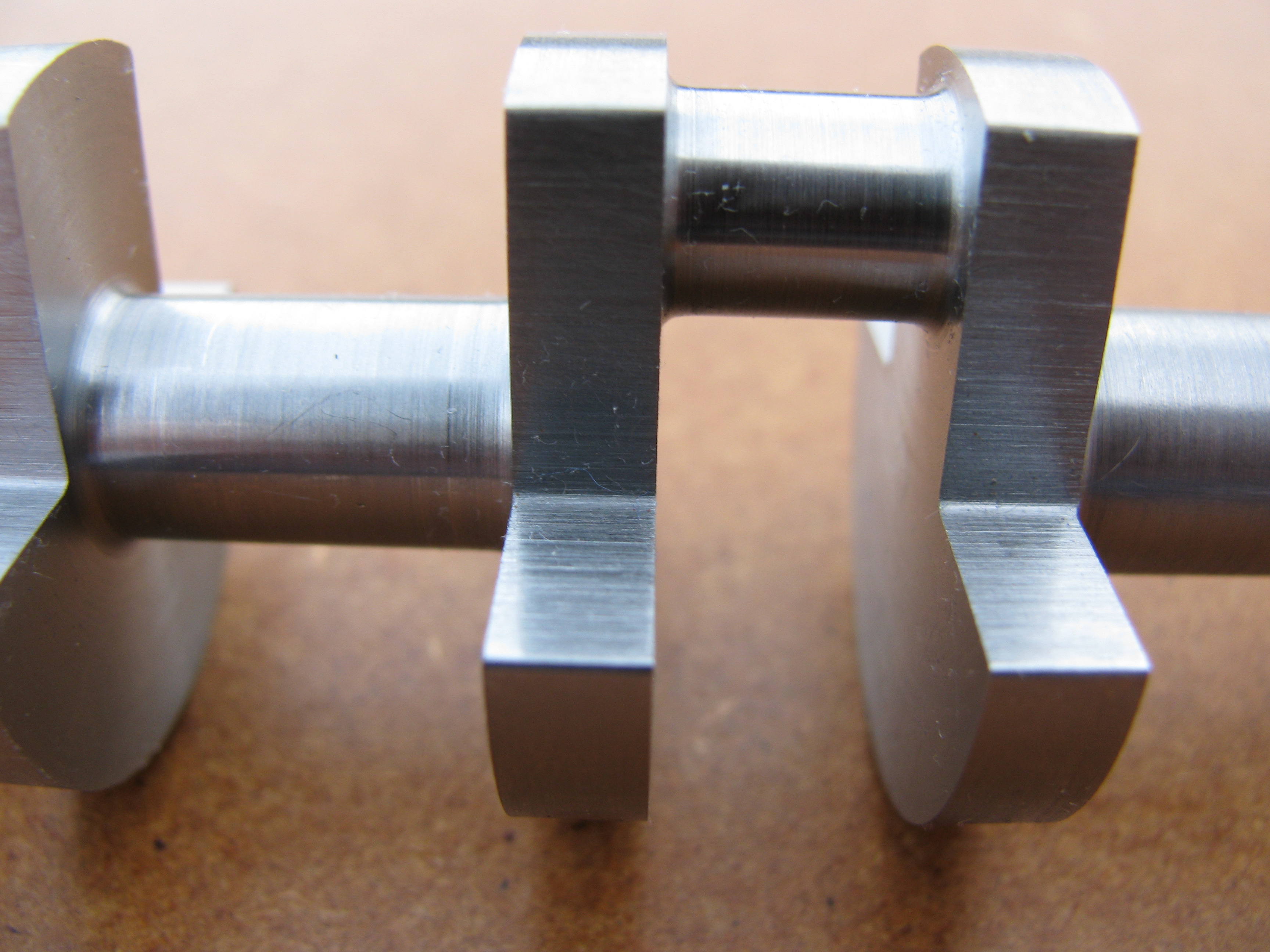
The balance weight cut-outs were milled today. I honed a 1⁄32″ radius on the slot drill to give a radius in the root corner of the notch. The result looks right. As I suspected, taking this metal away near the crankpins did result in a little movement, again opening the webs slightly so that the centre runout increased a thou to 0.004″. Clearly, this needs to be done before final machining of the important bearing surfaces.
This is usually a good rule anyway. Some folk like to get the tricky part out of the way, knowing the rest of the job will be plain sailing. I don't work that way. Leaving the most critical bits till last not only ensures that any distortion is taken care of, but gives me more time to chew over how to do it, and to screw up my courage. Of course, it means that you throw away more work when you screw up the job instead, because you can just get it finished before you have to go in, knowing that you won't get another chance for a week. Don't. I mean never. Leave it. Sweep up instead. (3 hours)
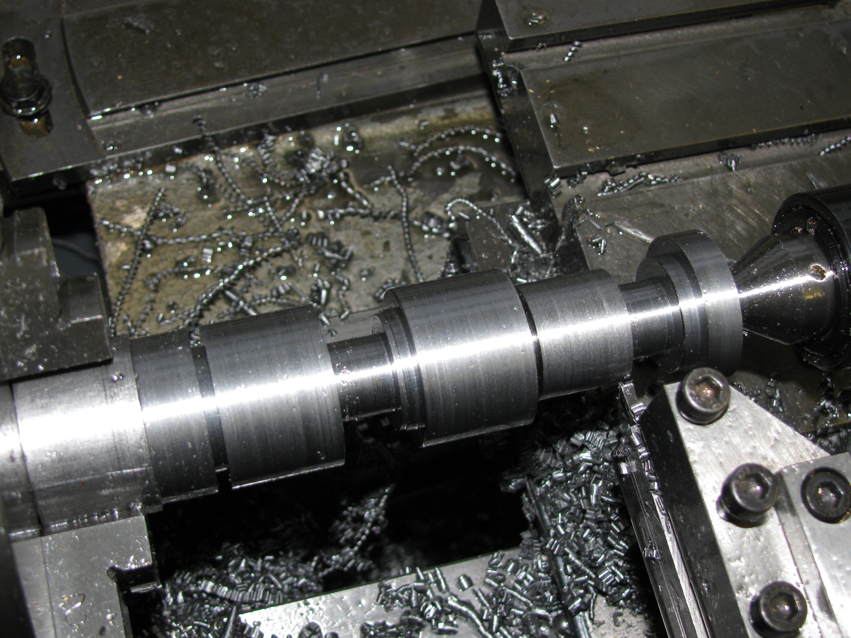
2010-02-13 - Finishing the crankpins 2
Measured up the crankshaft for crankpin machining, and finish machined No 2 pin (flywheel end), and readied No 1 for final cuts. I took the final shavings in bottom back gear. It does not take long and the resulting finish was pretty good. (6 hours)
2010-02-20 - Finishing the crankpins 1
I finished the crankpins today. Not bad, but not perfect. No 1 pin measures dead size, but No 2 seems to be slightly tapered, and about 3 tenths down on size at worst. I have given them a very light polish with a narrow strip of 800 grit wet-or-dry. This takes the crests off the ridges, and should make fitting and running-in easier.
Getting accurate length measurements in among all those crank-webs is not easy. You cannot get a micrometer in, and it is sometimes hard to get a convincing reading with a vernier. Over the last few years I have been filling out my toolmaker's chest with acquisitions from eBay. It is this kind of situation that I have found a set of slip gauges (gauge blocks) really come in to their own.
You can measure the crankpin gap between the webs to 0.0001″, and with both gaps filled with stacks of slips it is easy to measure between the stacks with a third set. Using this method I have got the 'inside' (next to the crankpin) web faces all well within one thou of the right place. (2 hours)
2010-02-21 - Spaced out
Conventional wisdom requires us to fit spacers at this stage, in the gaps between the crank-webs. I tried it, and I am unconvinced. I suppose I did not try very hard, but I was unable to get a fit that was sufficiently tight to stay in place, even though wired to the crankpin and yet not tight enough to cause a measurable amount of spring. When one slipped out of position I gave up and took both off. Results so far suggest that good concentricity, roundness and parallelism can be had without. The centre journal was machined to +0.007″, the outsides of all four crank-webs to about +0.002″, and at both ends the discs with the crankpin centres were machined off and the journals reduced to 13⁄32″ diameter. (3 hours)
2010-03-01 - Centre journal
The first job was to rub the machining marks out of the balance weight cut-outs. I found the best way to go was with 180 grit wet-or-dry(lubricated with paraffin, as I usually do) wrapped round a strip of steel. I rounded the edges a little too, although there is still a finishing cut to be taken on the OD. Next, I did a bit of tickling up on the root-radius tool as it seemed to be beginning to rub a bit. This tool still seems to give the best finish, so I will probably use it for the outboard journals as well. After that, the centre journal and webs were finished today. I got the diameter to 0.3752″ which I was quite pleased with. (3¼ hours)
2010-03-02 - A Quandary
I only took a 10 thou cut on the flywheel end main journal today. Checking this showed a 0.001″ taper along it, so I will have to think about that. After doing that I decided to check on the truth of the centre journal, machined yesterday. It looks as if I had the centres a bit tight again, as this is showing a good thou of runout. That is rather a disappointment, as the size and finish are spot-on. Do I leave it to bed in, re-machine it undersize, or try to get it true with a bit of selective polishing? (½ hour)
2010-03-09 - Finishing the main journals
Further investigation showed the centre journal runout to be 0.0012″, and the freshly turned flywheel end journal also had a runout of 0.0008″, both high away from the crankpins as usual, showing that the crankpin gaps have been closed up by the end load from the centres, and there is a thou taper along the journal. This is not good enough, and some investigation and head scratching is in order. A 10 thou cut at the timing end resulted in a the centre pressure stiffening up during the cut and, when reset, a runout by the web of 0.0009″. Another 2 thou cut was squealy and uneven and I had to tighten the tailstock part way through. This was again unsatisfactory. There could be a problem getting enough friction to turn the revolving centre without imposing too much end load, so I tried a dead one. After another 2 thou cut even this had tightened, and there was still a runout of 0.0008″ at the web. At this point the diameter was +.0038″ at the end and +0.0040″ at the web. At least the taper was much less.
I tried just letting the lathe run without taking a cut. It seemed that the centre pressure had tightened up after a few minutes running, so it may be best to leave the lathe running as much as possible, and to allow, say, 5 minutes for the job to warm up before taking a cut. It was noticable that the lathe was a rather warmer than the rest of the workshop, and the motor cooling fan wafts warm air towards the work. I also had another go at fitting the packing blocks between the crank-webs. I adjusted them so that they were a very light fit between the webs, not tight enough to stay in place even when stationary, but found that even so I had to use more end pressure at the centre to bring the runout back to the same as before. The blocks were wired to the crankpins but still tended to slip out of position, so I abandoned them again.
The taper showed up on a clock moved along the flywheel end journal, so the work seemed to be springing. Although it was still producing an excellent finish, and was the tool to use for the root radii at the transitions, it was evidently causing the work to spring. I changed to a more normal right-hand turning tool and took a cut of about 1 thou. This gave a diameters at the end of +0.0011″ and at the web +0.0013″. The runout was 0.0003″. The surface was not as good as with the broad-nose tool but still pretty fine. This was all much more acceptable, though not perfect. I decided to go for a finish cut. Setting the depth was not easy, and I had to try and back off twice over the front portion before getting it right with just enough room for the full length of the bearing surface. The result was +0.0002″ at the end of the journal, +0.0005″ at the web, and a runout of 0.0003″.
Moving to the timing end journal, this now went quite straightforwardly. Three finishing cuts were taken, resulting in a journal diameter +0.0002″, with a runout of 0.0001″. The next job was to take the last shave off the outside faces of the outer crank-webs, using the broad-nosed radiusing tool again, and again allowing the tool to take a final shave across the webs on the final outfeed.
Finally, I turned the last couple of thou off the outsides of the crank-webs and chamfered them 10 thou. (5 hours)
2010-03-10 - Trying to tweak the runouts
After finish turning the main journals I did a survey of the shaft between two dead centres and on vee-blocks. In the vice I tried selectively polishing the flywheel end journal with narrow strips of 800 grit wet-or-dry paper. The result was that I polished the surface, removed the taper, reduced the runout - and produced a shaft about 0.0002″ out of round. As the diameter was now down to size it was left at that.
Turning to the 0.0013″ runout of the centre journal, I decided that was too much to leave. Holding the timing end journal in an ER collet, it ran out about 0.0001″, which was pretty good. There was a little bit of a wobble at the tail end but I supported the end with a centre anyway. Turning out the eccentricity of the centre journal left it 0.0015″ undersize, and a little polishing took it to -.0017″ at the lowest. On vee-blocks, the centre journal runout was now down to 0.0003″, and this was now to one side rather than away from the crankpins as it had been. I decided to leave it at that, at least until fitting.
I turned and reamed a 5⁄16″ gauge for the timing gear seat. This went slightly too easily over a piece of silver steel measuring 0.3127″, so I will aim for 0.0313″ for a fit. Turned the seating to that size, which is indeed a nice push fit in the sleeve. If anything it could have been a shade tighter. Lastly, I turned the ends down to ¼″+ for the threads. (5½ hours)
2010-03-12 - Taper and thread

I set the taper turning attachment up to 5°. Using a dial gauge over a set length (2½″ measured by engaging the half-nuts) it was possible to get within a thou over that length. I turned the flywheel seat at that setting, and ought to make the flywheel before disturbing it (boring the taper with a tool upside down, cutting at the back).
I ran into a bit if trouble today turning the thread at the flywheel end. After grinding my threading tool to be able to get closer to the shoulder I seemed to have difficulty picking up the thread at the start of each cut, and I still don't understand why. I was using the method in which you leave the top-slide square and advance it by half the cut you put on with the cross-slide. This is not my normal method. I usually use method of setting the top-slide at the thread half-angle. I normally finish threads using a doctored (well vetted, really - I dock their tails) hand chaser as a machine chaser. This was playing up too, today. I ended up with a thread that is perfectly good on the back flank which is the bit that matters because that is where the nut bites, but is rougher than I would expect or like on the front flank. (2½ hours)
2010-03-13 - Last operation
After regrinding the threading tool and sharpening up the chaser, I screw-cut the timing end, using my preferred set-over method. This went much better, producing a clean thread that is a good enough fit to find the difference between the two supplied nuts. Crankshaft finished (oh, except for a keyway for the timing gear). Tidy shop and clean and lubricate the lathe. (3 hours)
.
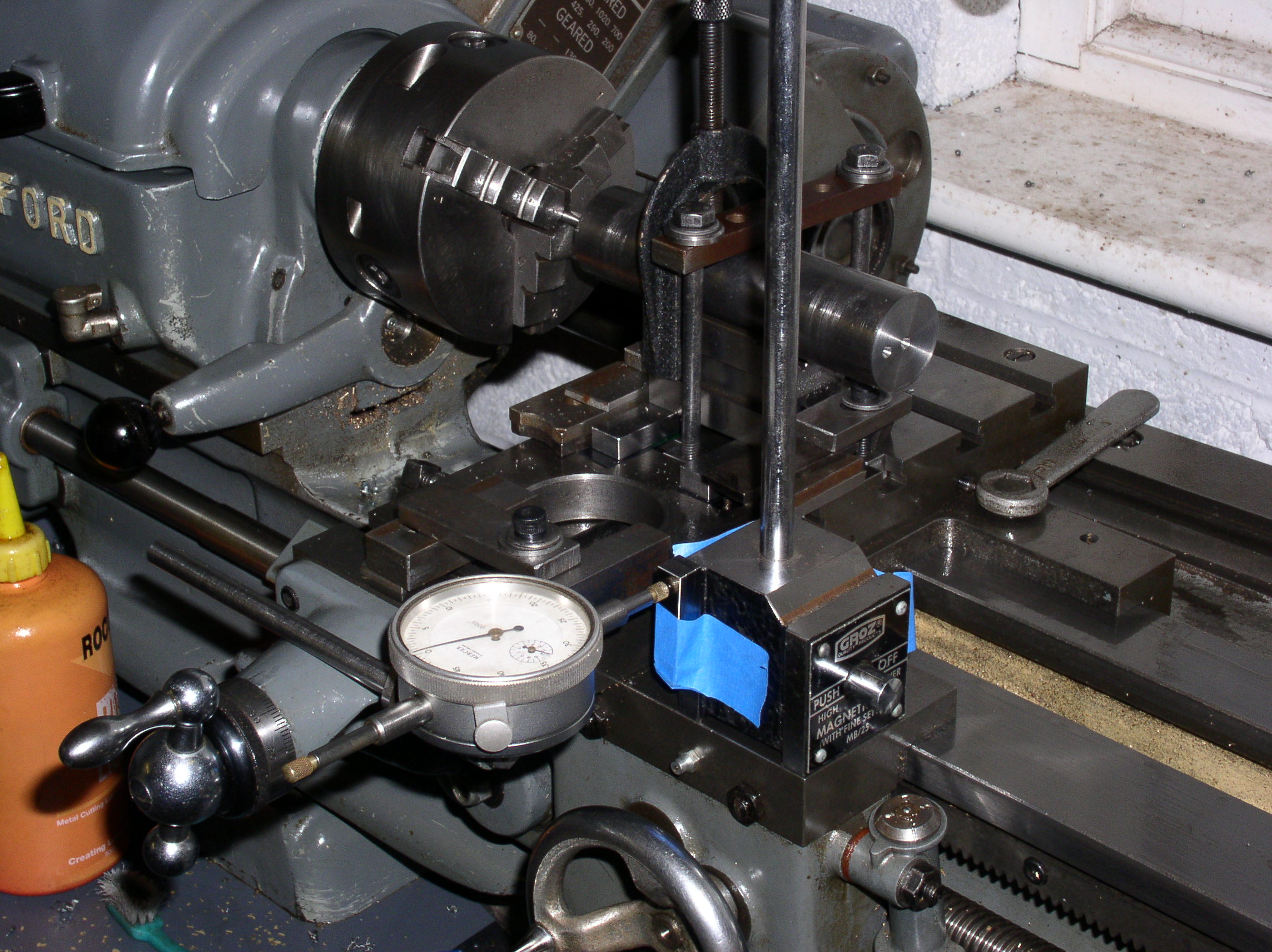
2013-01-10 - Really the last operation, part 1
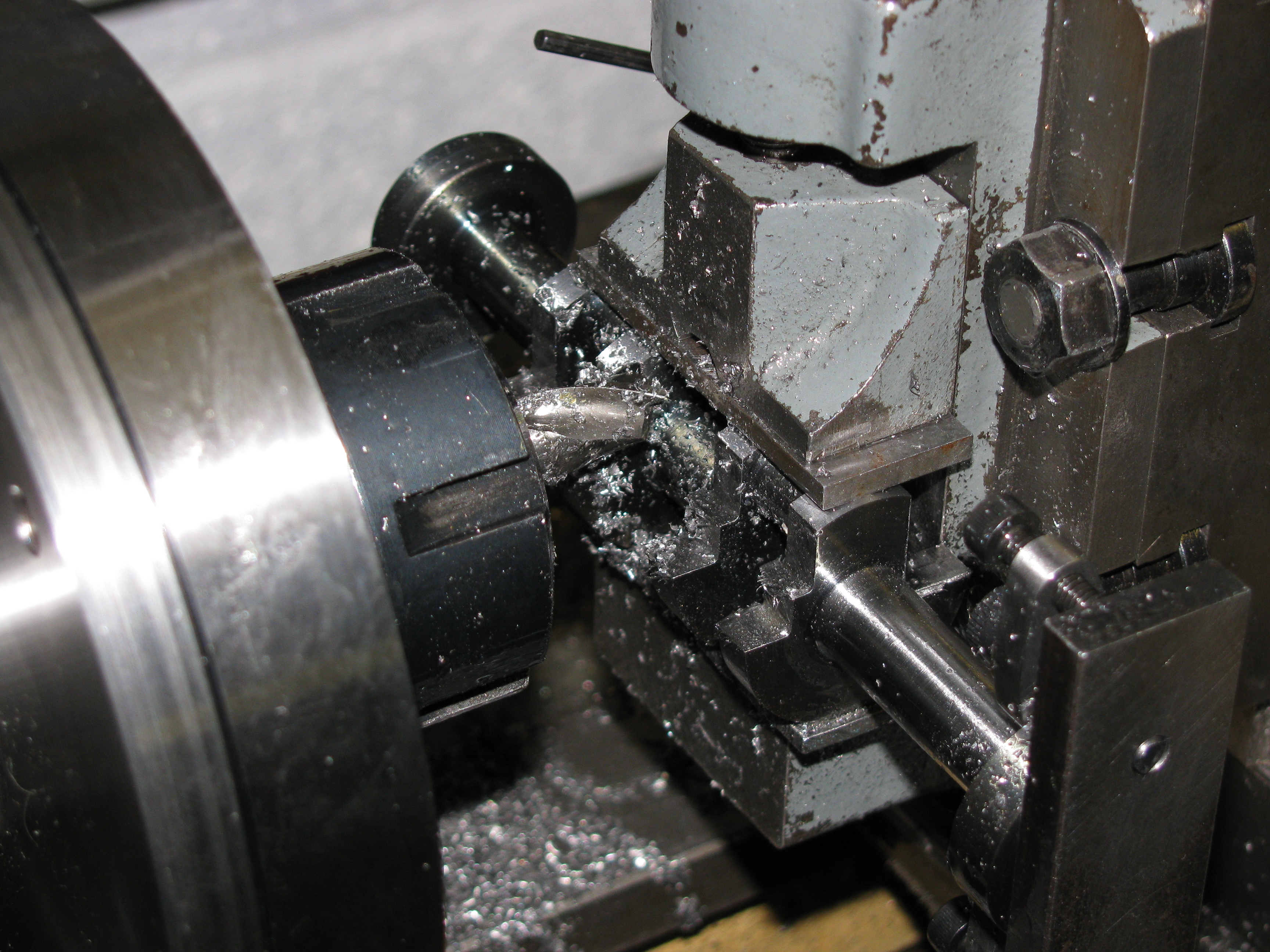
The keyway for the timing gear needs to be accurately milled, and deciding how best to hold it caused some head scratching. I decided to do it properly with a pair of blocks to mount it on the vertical slide. Sketching these up prompted me to use a piece of bought tee-nut section bar to make some M4 tee-nuts for small jobs. With these finished I started work on the posts, hacksawing them from aluminium alloy stock and milling the blocks to size. (3¾ hours)
2013-01-12 - Really the last operation, part 2
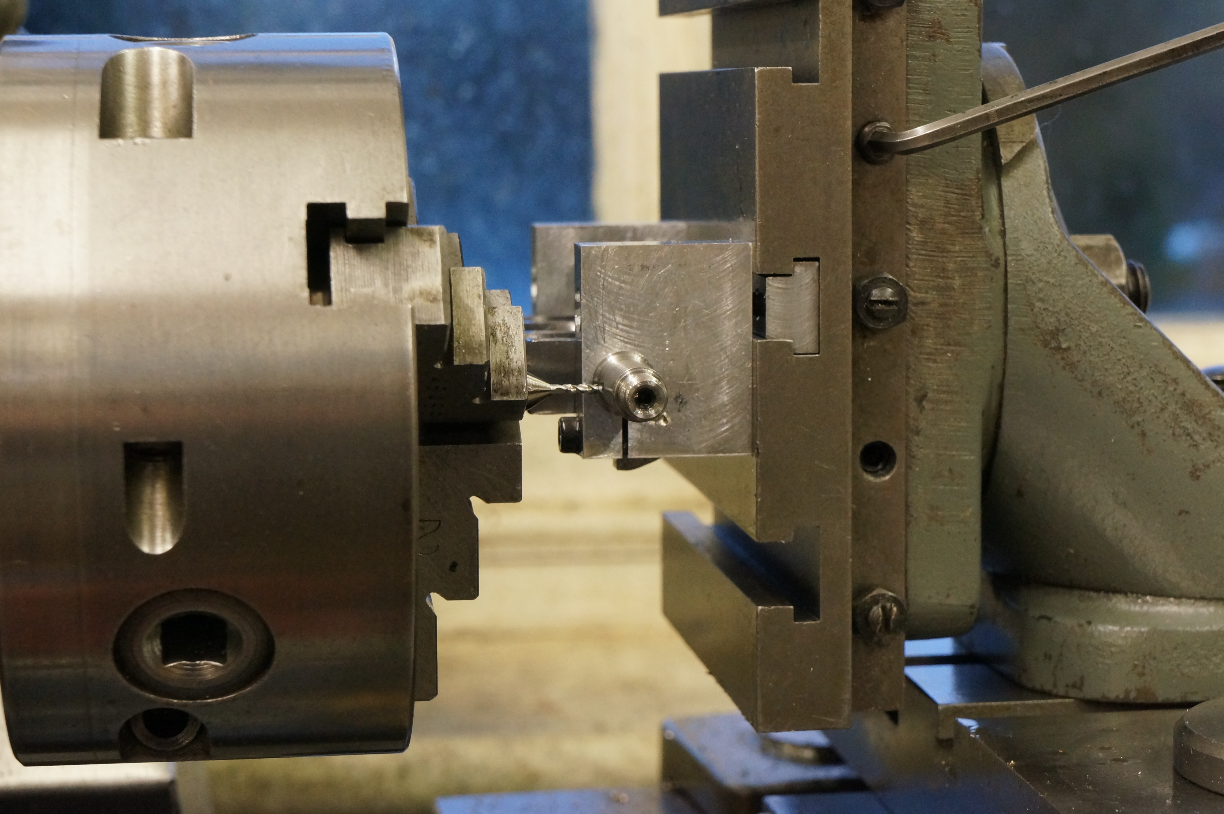
I drilled, reamed, and tapped the various holes in the crankshaft mounting blocks and cut the slits. (2 hours)
2013-01-26 - Really the last operation, finale
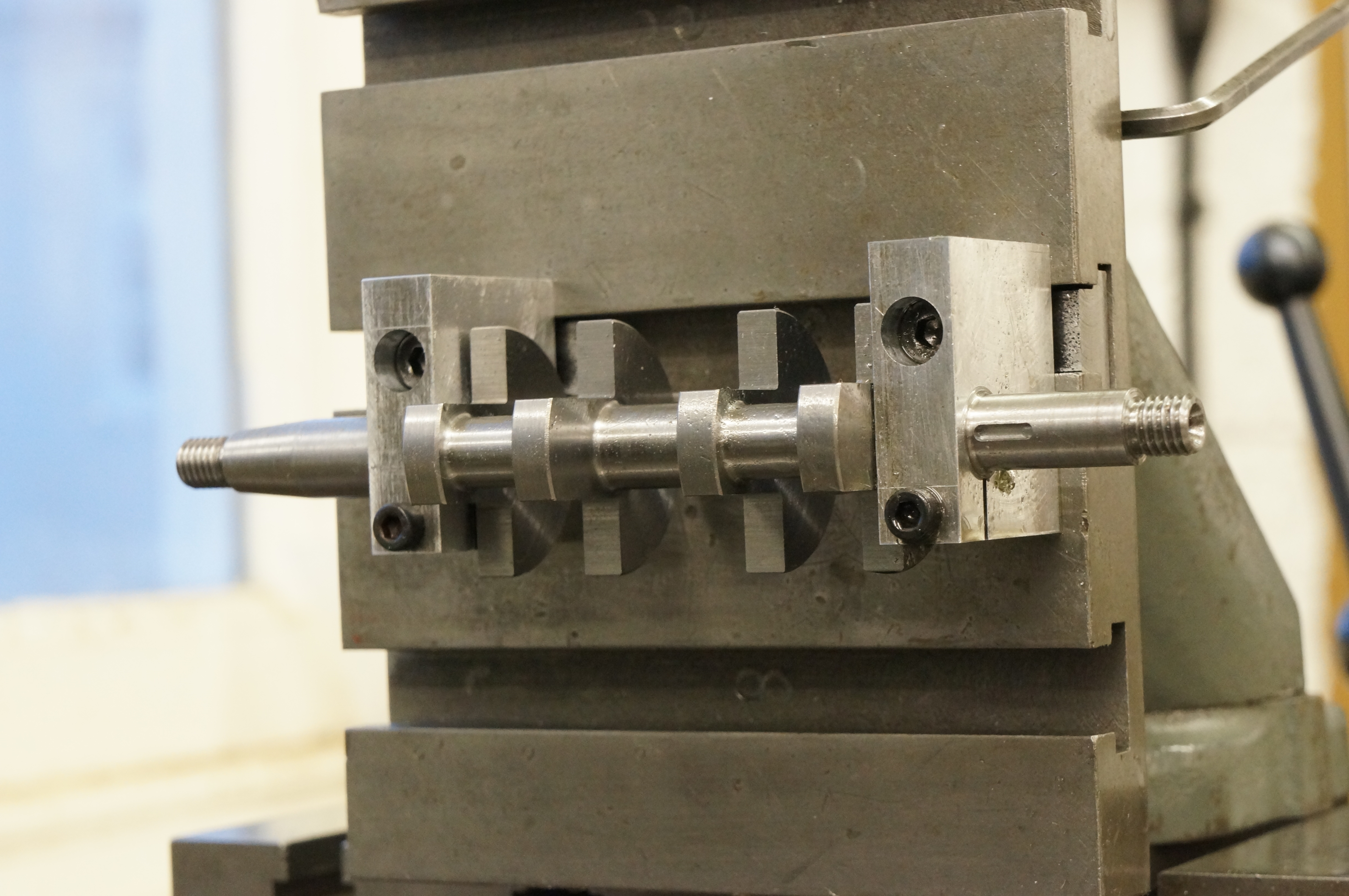
With the keyway cut in crankshaft pinion, and keys made to fit, I could at last cut the crankshaft keyway. Even with the blocks, setting up needs a sequence of steps. First, everything is just temporarily tightened in roughly the right position. Second, the block bolts are slackened a little and the two crankpins brought level. Third, the block bolts are tightened and the shaft clamp screws slackened so that the crankpins can be levelled with the timing end of the shaft, made easier as these are the same diameter. Finally the vertical slide is adjusted to get the shaft on centre line. This is pretty important to get accurate, as a 0.001″ error at the keyway shifts the timing by ½°.
With everything set up I milled the keyway with a 1.5mm slot drill with the VFD wound up a bit over 60Hz to give 2500rpm, taking a couple of passes to get to depth. After measuring, I took a further 1¼ thou off each side to fit the key and 5 thou at each end for clearance. The key was a nice fit and the gear would push on most of the way without difficulty. Once all stripped down and cleaned up, the fit proved to be really nice, which felt like vindication of the fixture making. (2¼ hours)
So that is a total of about 67 hours work for the crankshaft. Phew.
.