
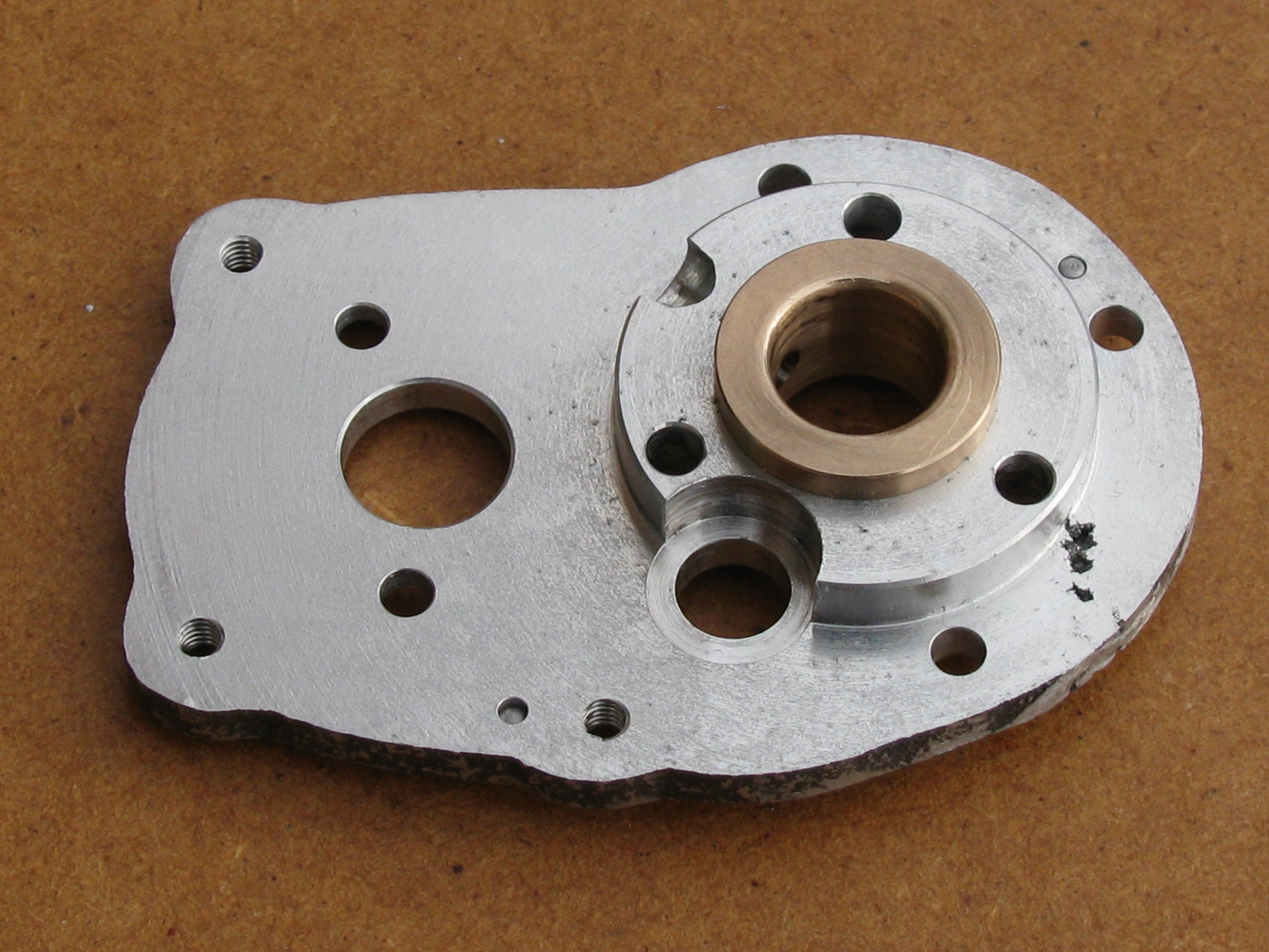
Timing End Bearing Housing
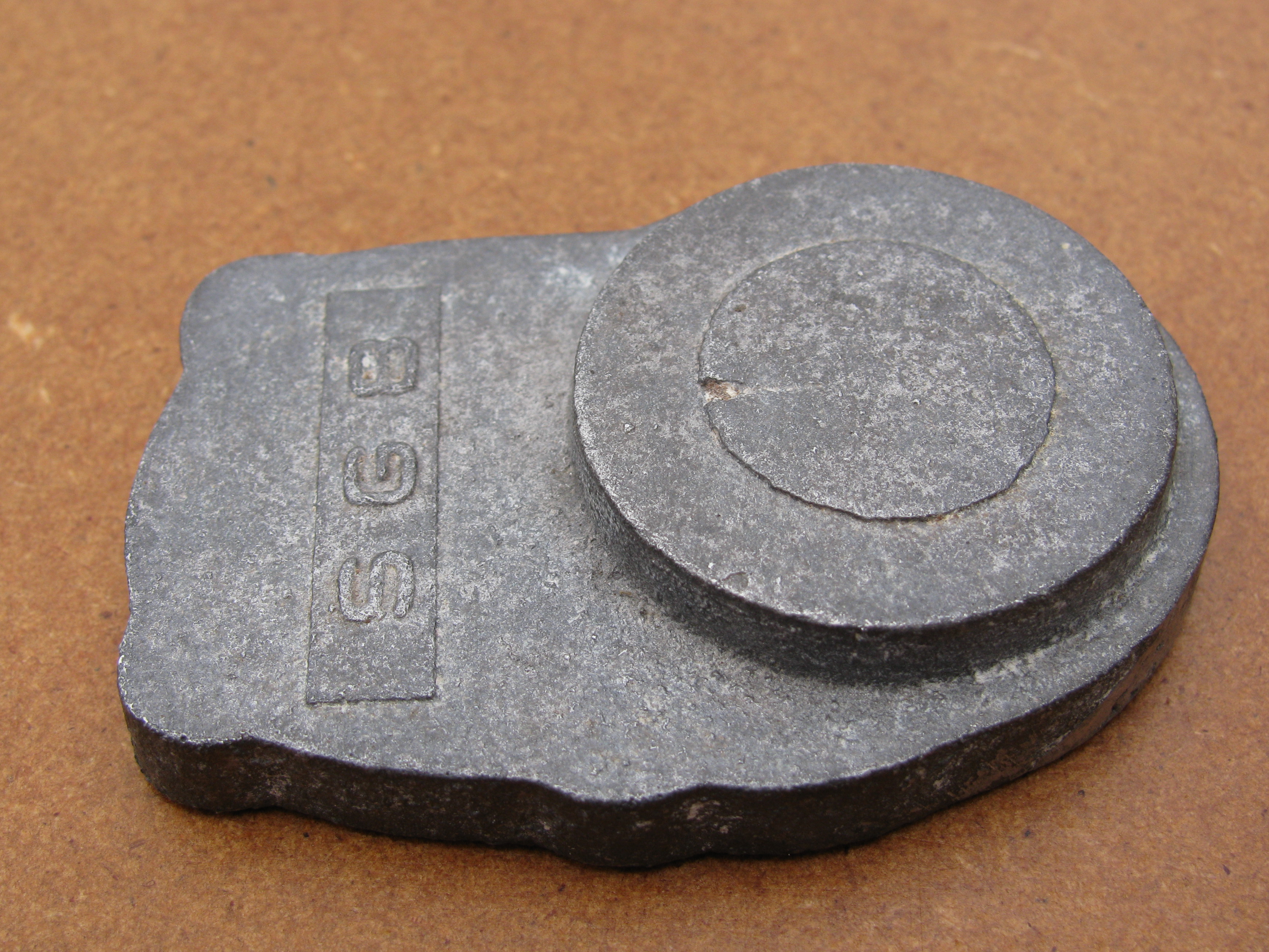
The sequence for machining this part and the timing case needs to be carefully thought out to get the best results. The machining considerations are: getting the main spigot diameter and bearing bore concentric and in the right place in relation to the timing case, finding the right angular orientation, getting the camshaft bearing hole in the right place, and repeatable alignment with the timing cover.
The position of the crankshaft hole is probably best determined from the combined unit, setting the boss on the timing case to run true, as there is not much metal round it and any eccentricity would be conspicuous.
Concentricity of the spigot and crankshaft bore can be achieved by machining these at the same setting.
The timing case and bearing plate therefore need to be aligned for the best match of the external profile and drilled for fixing holes quite early on. The cover ideally wants to be dowelled onto the plate, though it is difficult to find room for widely-spaced locations. It may be necessary to put both dowels in the lower region where the joint face is much wider.
It may be possible to machine the camshaft bearing hole in the timing case in situ at the same time as the camshaft hole is bored in the crankcase, but as the orientation is not accurately known until this stage, the bolt holes will not have been drilled. Equally, I am not too keen on the idea of swinging the crankcase on a ½″ mandrel. On the whole, doing it at a later stage seems more workable. The camshaft bore can be located using a ½″ button in the camshaft hole in the crankcase. This can then be set to run true on the faceplate in the usual manner.
I don't like the arrangement for mounting the Idler Stud on this plate. It is provided with a thin flange so that it can be held by two 8BA countersunk screws, and is then additionally held to the timing case using the 4BA thread on the end of the stud flapping about in a ¼″ hole in the timing case. I see this as presenting difficulties in ensuring it ends up in the right place, and as not being very strong. I have been looking at a number of ways to improve it. A machined hole in the plate would provide a more definite location, and it could be set out using a 5⁄16″ toolmakers button to mesh the gears. Fixing the stud still presents a problem, especially as it is close to the edge of the housing spigot, and a through hole is likely to cut into the crankcase and sump. A hole tapped into the conjunction of the three parts is possible, but does not appeal as sound engineering. A short pin with a broad flange, fixed into the housing with Loctite is perhaps the simplest idea. Alternatively, a 3⁄8″ clearance hole through the crankcase and sump, and a corresponding recess in the bearing housing spigot, would just about provide room for a retaining nut or the head of a bolt ( hollow, for the oil way) to hold the stud from the inside. The stud can be supported at the outboard end by making it a fit in the hole in the Timing Case which is accurately located by the dowels. Fixing the stud solely to the timing case might be easier to do in some ways, but I cannot think of a good way to find the right position to get the mesh right.
The timing end face of the crankcase and sump need to be lapped flat and square to the sump joint face at some point to ensure the plate sits flat against it and the bearing is aligned.
Fixing the bearing housing and timing case to the crankcase with just the three lower bolts seems unsatisfactory to me, leaving the assembly insecure. I will be putting an additional pair of countersunk screws through the plate, near to the camshaft.
So the sequence is: rough out the outside face; rough out the inside, finish the outside face, spot or drill the timing case fixing holes from timing case & tap; drill dowel holes and fit the dowels; fit the timing case and locate the crankshaft hole from that, and fine bore both undersize. Next turn round and, without the timing case, set the bore true and bore to size, and finish turn the faces and spigot. While still in situ, Loctite the unfinished crankshaft bush in place, and finish bore and lap it. Again using the Timing Case as a guide for the lateral position, a preliminary hole for the camshaft can be made. If a button is made a firm fit in the crankcase, with a true bore a little smaller than this hole, the housing can be set by eye to the correct angular position and the button fixed in place. The camshaft bush is self-locating in the camshaft tunnel, so it does not need to be finish bored in situ. Bonding it to the housing in situ would be ideal, but I think there is too great a risk of also sticking everything to the crankcase.
2010-08-22 - Roughing-out outside
After finishing the funny angled holes in the crankcase earlier today, and tidying up a bit, I spent a bit more time contemplating the timing end castings. I took an exploratory facing cut off the outside surface of the bearing housing and made a start on cleaning up the periphery of the castings to see how well they match. I then made a start on the flywheel end bearing housing. (1½ hours)
2010-10-17 - Roughing-out inside, finishing outside
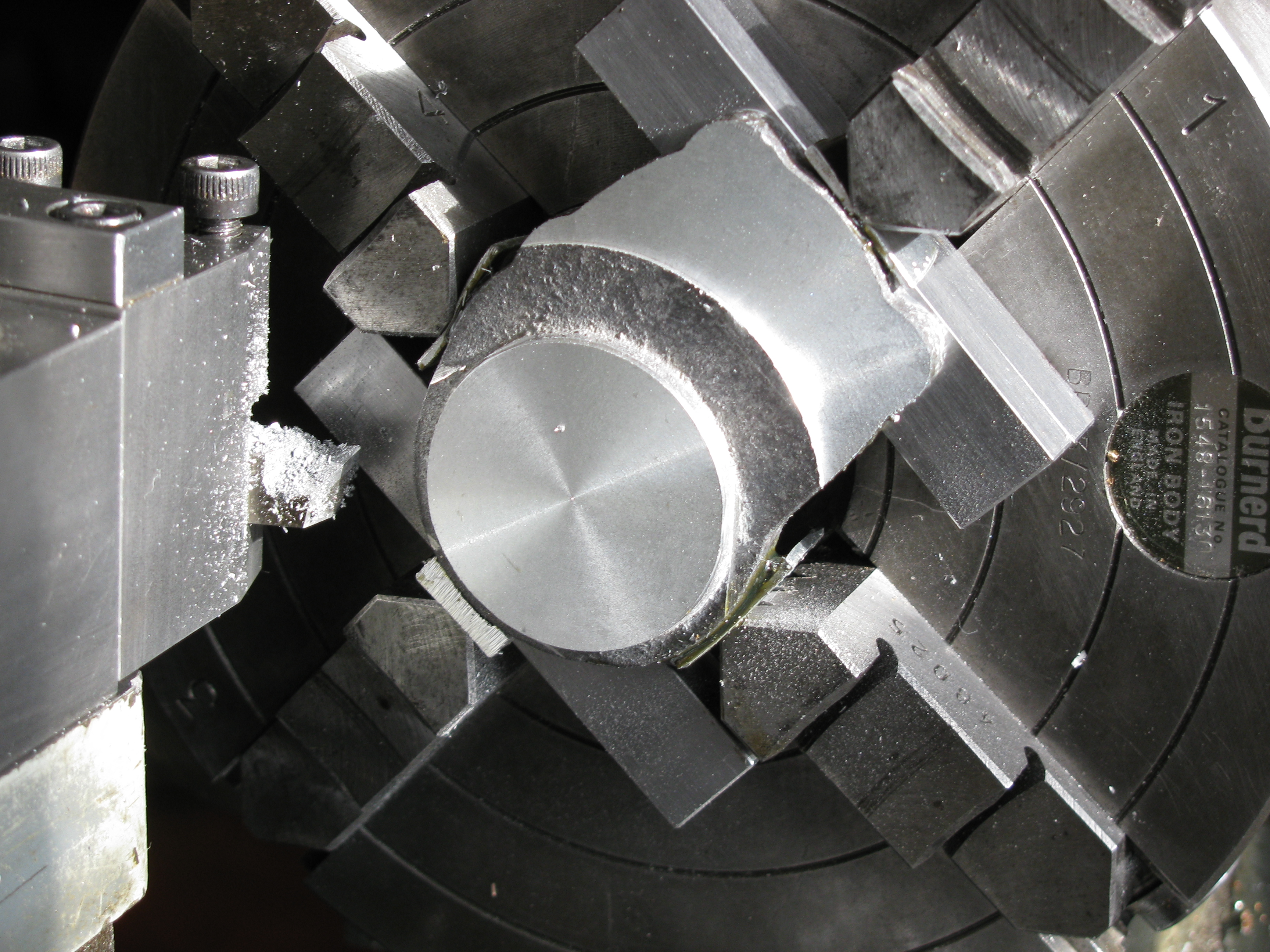
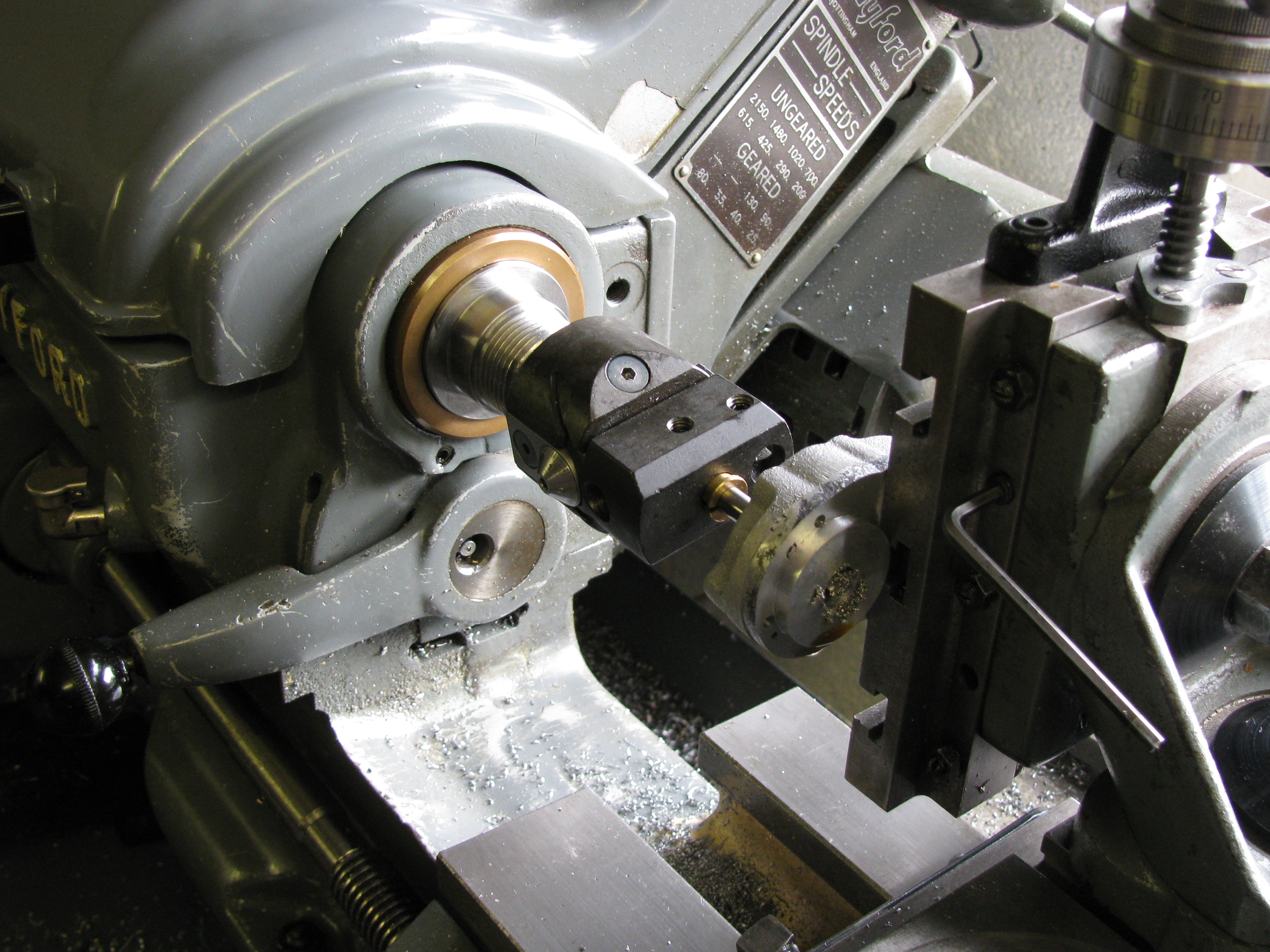
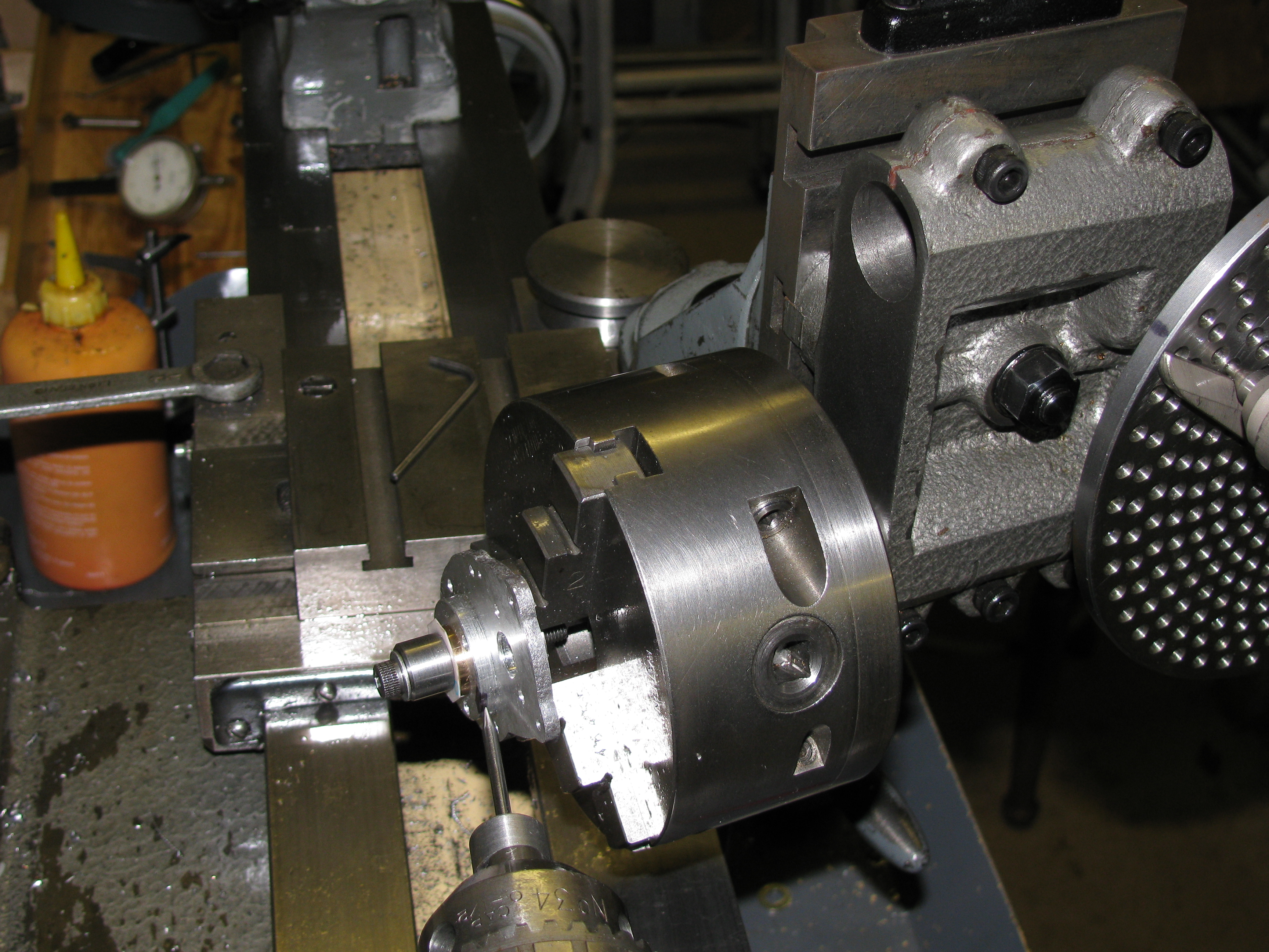
There is quite a bit of metal to take off this casting. I took 45 thou off the bolting face, 75 off the spigot face, and nearly 3⁄16″ off the spigot diameter. A small blow-hole is beginning to appear this side of the casting. The outside surface is still a bit spongy too, so it there will be a compromise in deciding where to take off the remaining 1⁄16″ of thickness. The photo shows packer behind the casting. A good firm set-up is needed if these are to be left in place (as I did) while turning. If there is any doubt they should be removed before running the lathe. It also shows that I use a dab of grease to help stop the softening shims from falling out every time a chuck jaw is moved.

After drilling the crankshaft hole a preliminary ¼″ for a clamping bolt, I took a little over half the remaining thickness off the outside face to finish it, in cuts of 15, 15 and 5 thou. I will need to be careful with the set-up for finishing the inside, as there is nearly a thou variation in thickness across the width of the plate at present.
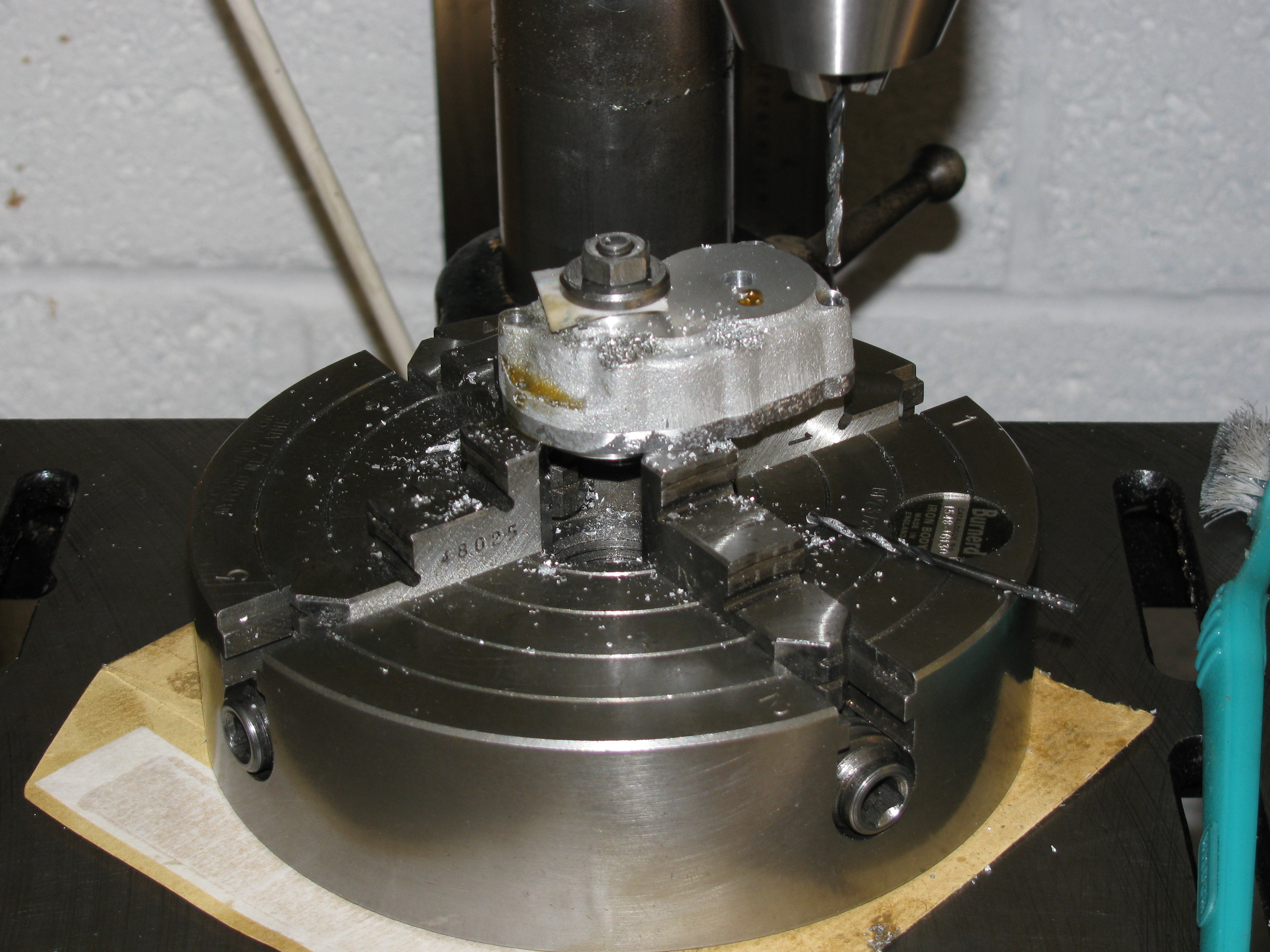
Next I clamped the bearing housing and timing case together, carefully matching the two castings at the periphery, and set them up in the drilling machine, borrowing the 4-jaw chuck as a machine vice (it is a threaded body chuck, so there is no backplate spigot sticking out). I transferred the 6 bolt holes to the bearing housing, through drilling the bottom 3, and tapping the others, as these do not go into the crankcase. (3¼ hours)
2010-10-18 - Doweling and cursing

With bolts in the newly threaded holes, I set the assembly up on the vertical slide, bearing housing side out to drill for two dowels. I drilled the holes 1.5 and 1.6 mm, which provides a fit that is just right for 1⁄16″ diameter silver steel dowels. After fitting the dowels, the parts can be snapped together with finger pressure, and only just wiggled apart without needing tools. This is gratifying.
With the assembly turned the other way round, I clocked up the camshaft alignment hole in the timing case, to transferred the hole to the bearing housing. This was also reamed ¼″.
Now clamping the pair by the new hole, I similarly transferred the crankshaft hole to the bearing housing. Using the boring head, both holes were opened up to about ten thou less than 3⁄8″ bore.
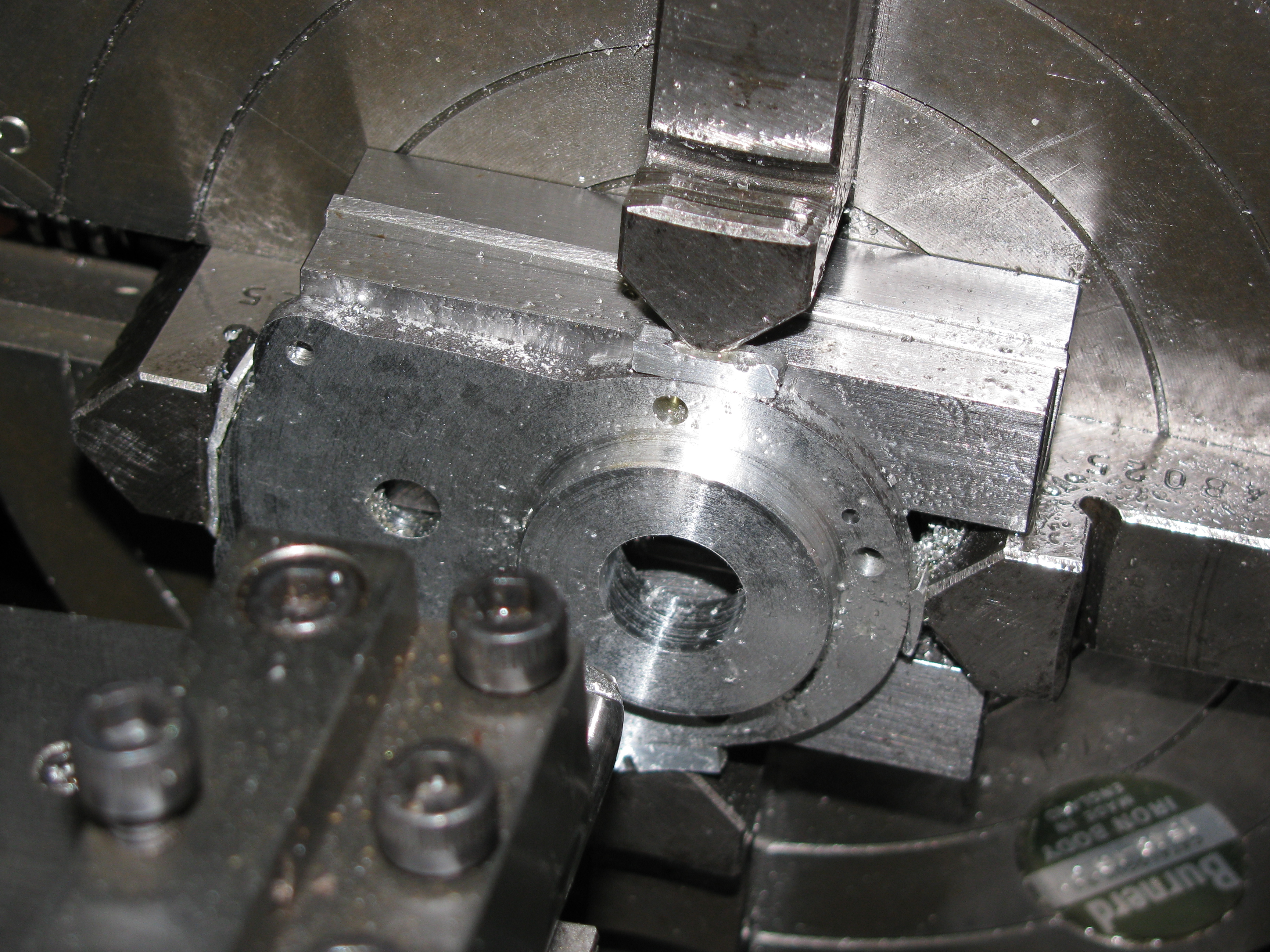
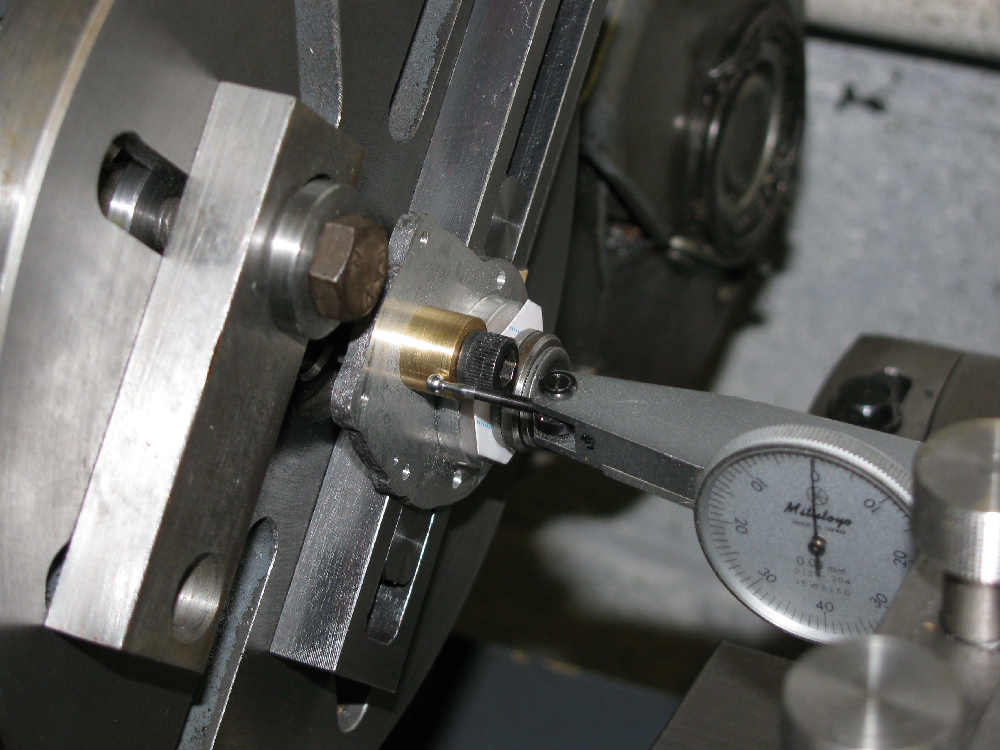
I spent half the afternoon with the next setup, trying to get the crankshaft hole running true. Setting such a thin part in a 4-jaw chuck is usually a pain, and this was more of one than usual. Every time the chuck jaws were move the tiniest amount, one of the stacks of packers would drop out. Naturally, to make it more awkward, this was the set with the equalising shim of cigarette paper. Every adjustment means the saddle has to be moved to get the dial gauge out of the way, and every time it is brought back in, the reading bears no relation to the previous one. Every time the job is knocked back against the packers it moves out of position radially. And to top it all, the bore of the alignment hole is too rough to get a really good reading. What is needed is a way to do without the packers, clamping directly against a true face. Something like a chuck with flush stub jaws, to which you can bolt clamping dogs of the right thickness.
After a mug of tea, I decide that I am just not going to be able to get better than 0.04 mm runout. As the timing case has yet to be finish bored from this part, the only features that will be slightly out of truth are the fixing holes. Once set, final facing and turning the spigot went without further trouble, and the spigot is a tiny smidgin over nominal size and fits perfectly with a firm push.
With the hole bored out to about 2 thou under size, I took the tool too far through, and clouted the one reversed chuck jaw. Only the tool is damaged, but it is time to call it a day. (6¾ hrs)
2010-10-20 - Boring the bearing
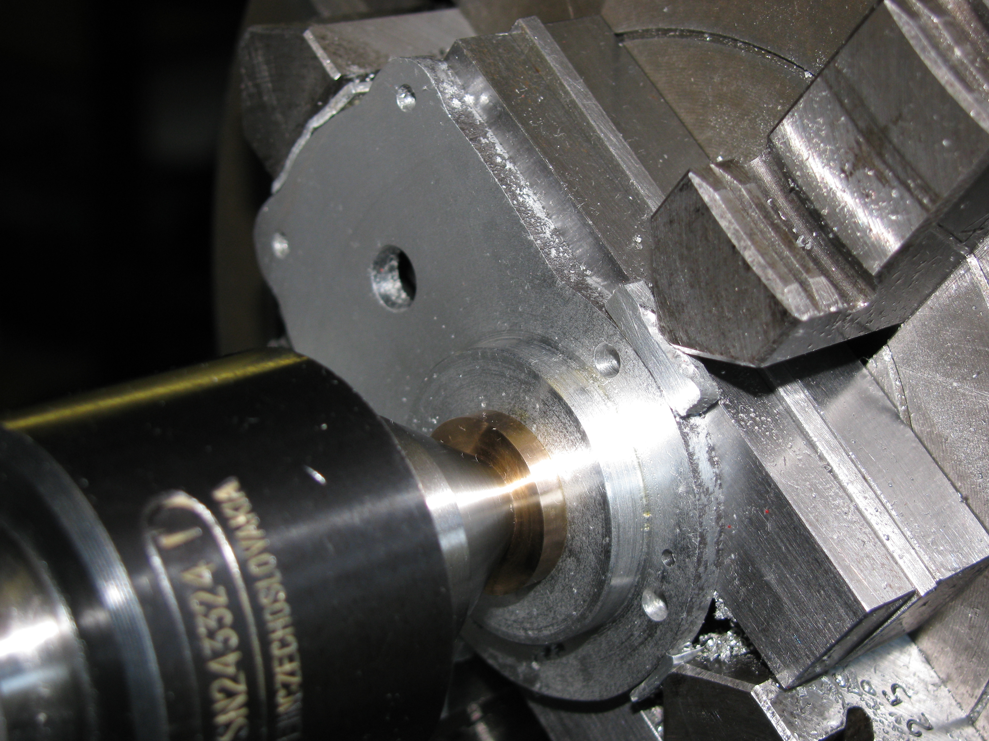
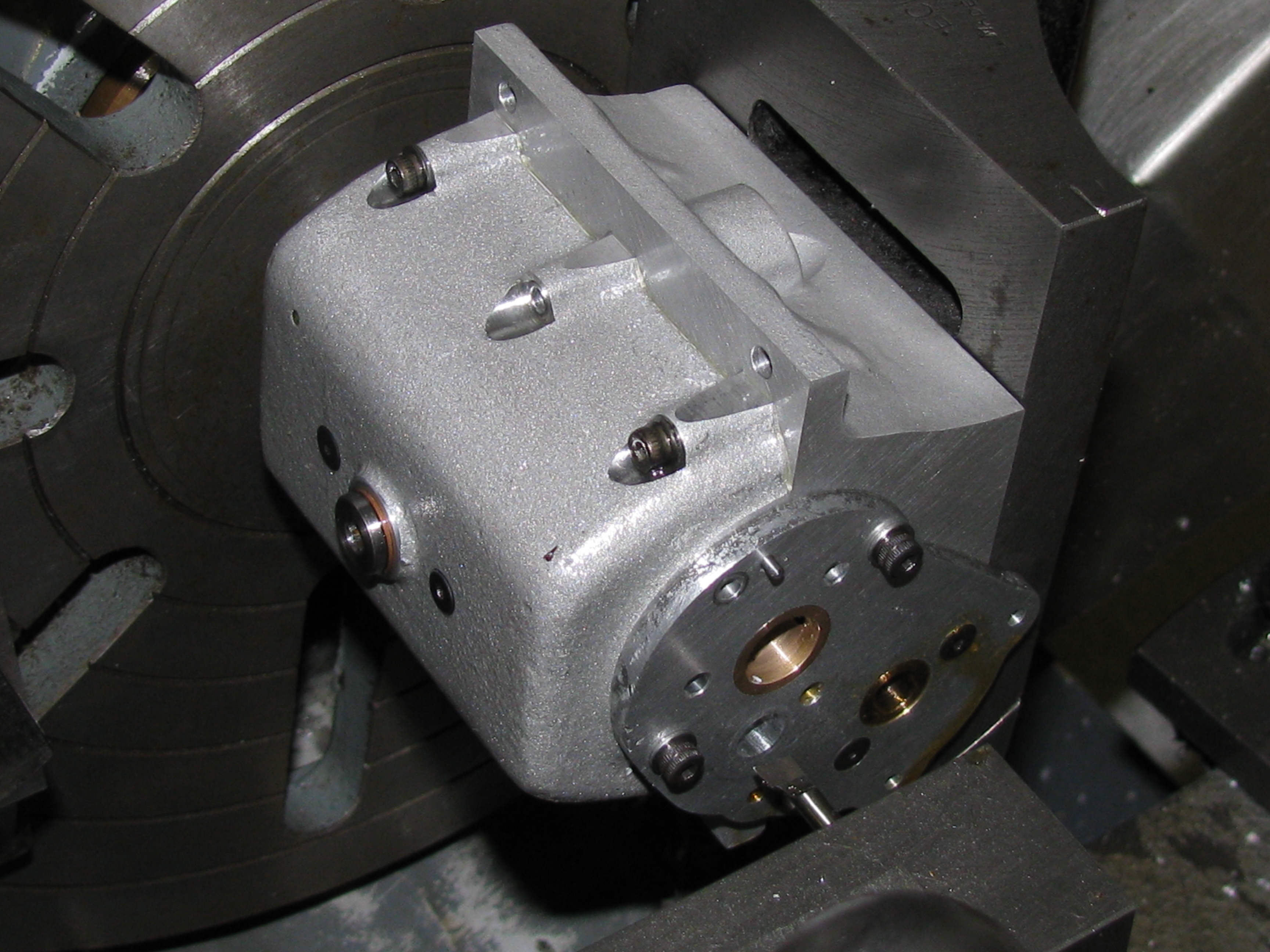
With only a minute cut available, it would be better to ream this to finished size, but unfortunately a reamer would suffer the same problem of hitting the chuck jaw, so it had to be bored. Making up three new boring bits from blanks helped, as the 3⁄8″ one worked very nicely. I was able to take 2 cuts of ½ thou and 2 of ¼ thou, allowing the bearing to push easily half way in. For a Loctite fit I took one more ¼ thou cut, cleaned the bore and the bush and Loctited it in with No 641 Bearing Fit. I used the tailstock centre to apply some pressure while it cured. The copper content of the bearing bronze ensures a rapid cure.
After facing the bearing to length, I started carefully opening out the bore with a new 5⁄16″ silver-steel boring tool at quite a low speed. Light cuts produced a taper of about 0.0002″ over the length, and I worked gingerly up using 5 cut settings, most of them put through twice, to remove the 10 thou I had left for finishing, to a maximum size 0.0004″ below 3⁄8″. I decided to leave it there for final lapping.
Finally, to start to form the the radius, I first chamfered the hole at 45° and then using my indexing toolpost, took secondary cuts at 22.5° & 67.5°, the cuts being taken to calculated depths. After stripping the job I had a tidy up. (4½ hrs)
2010-11-05 - Camshaft hole, final answer
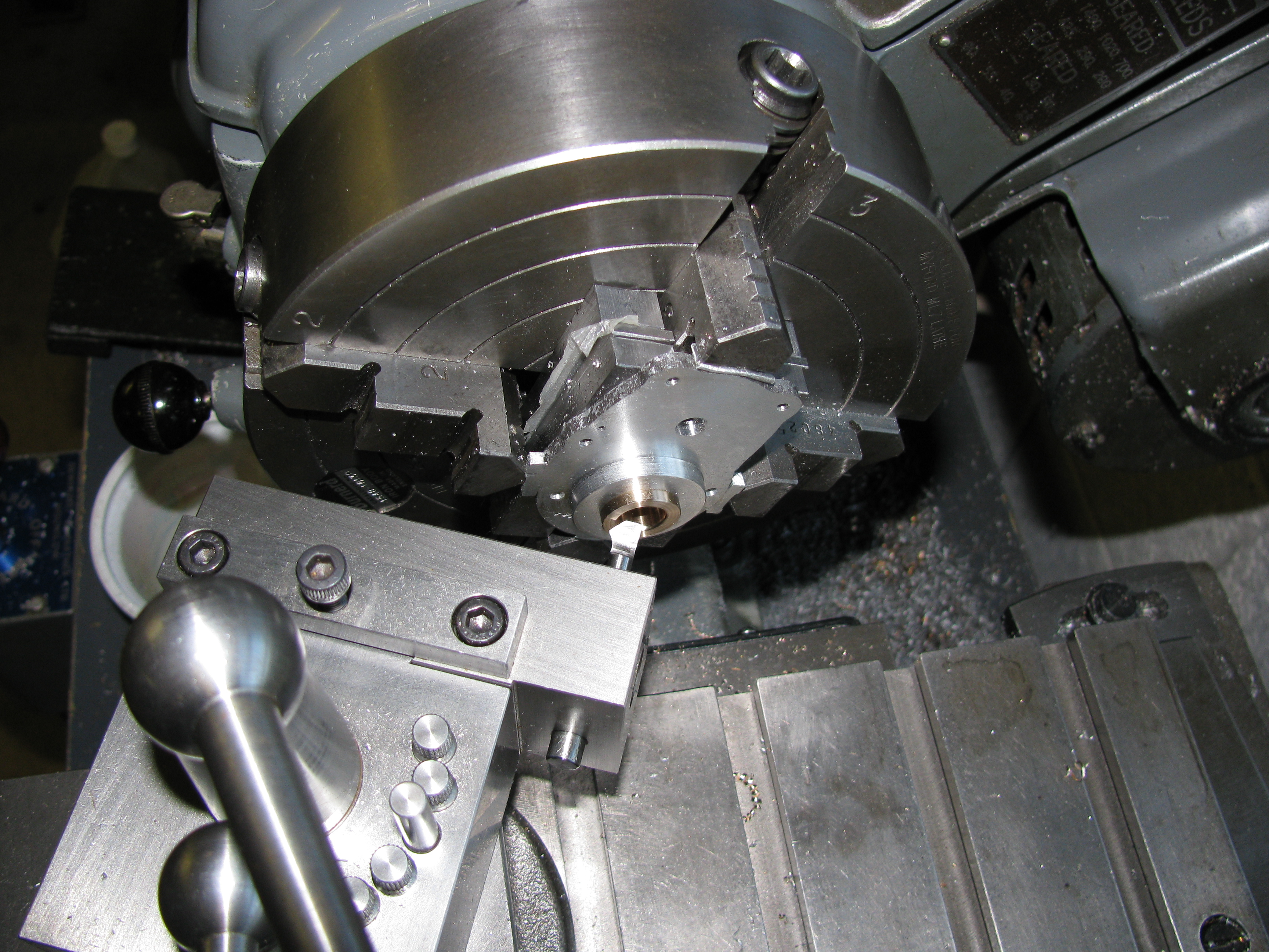
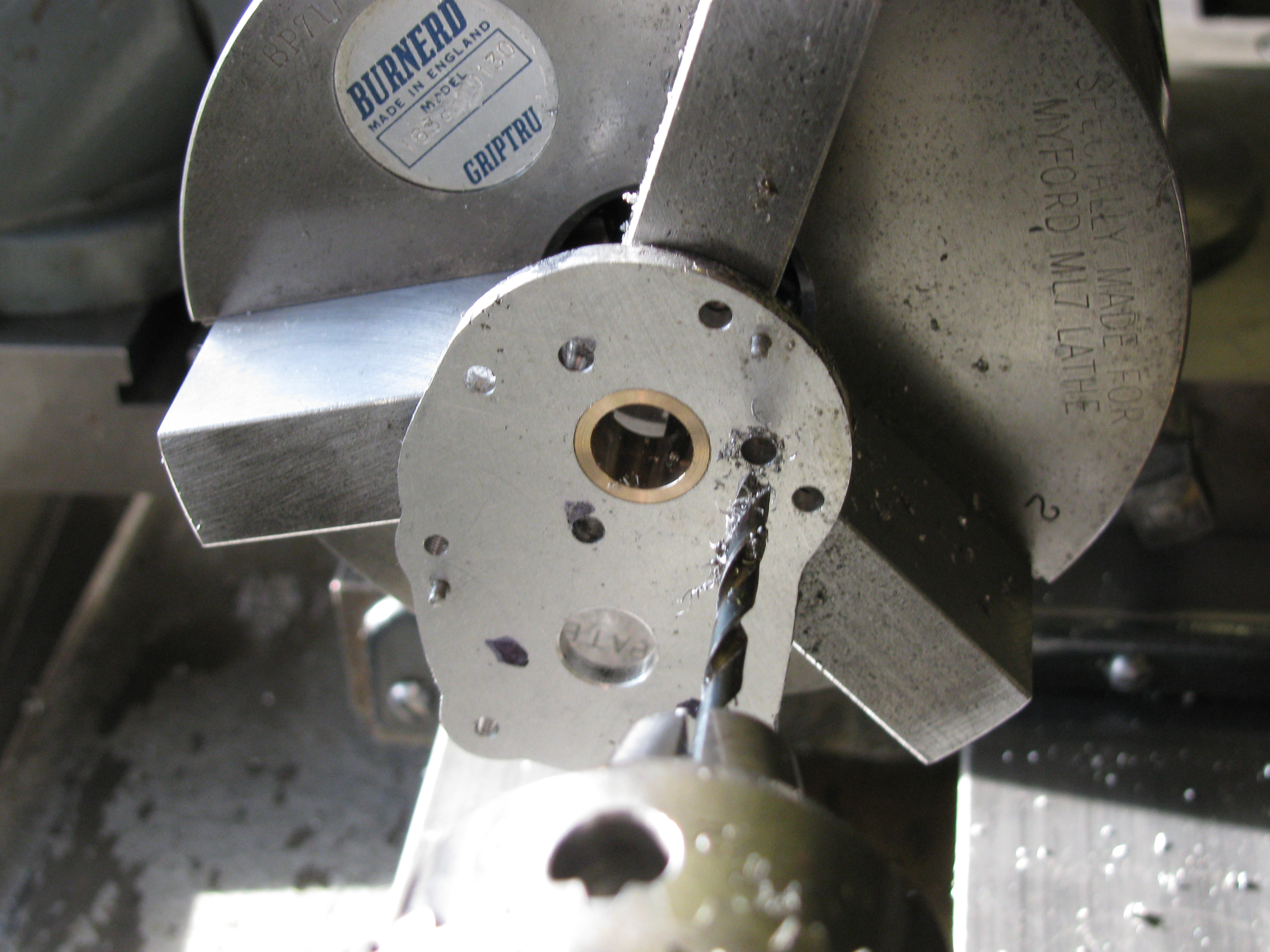
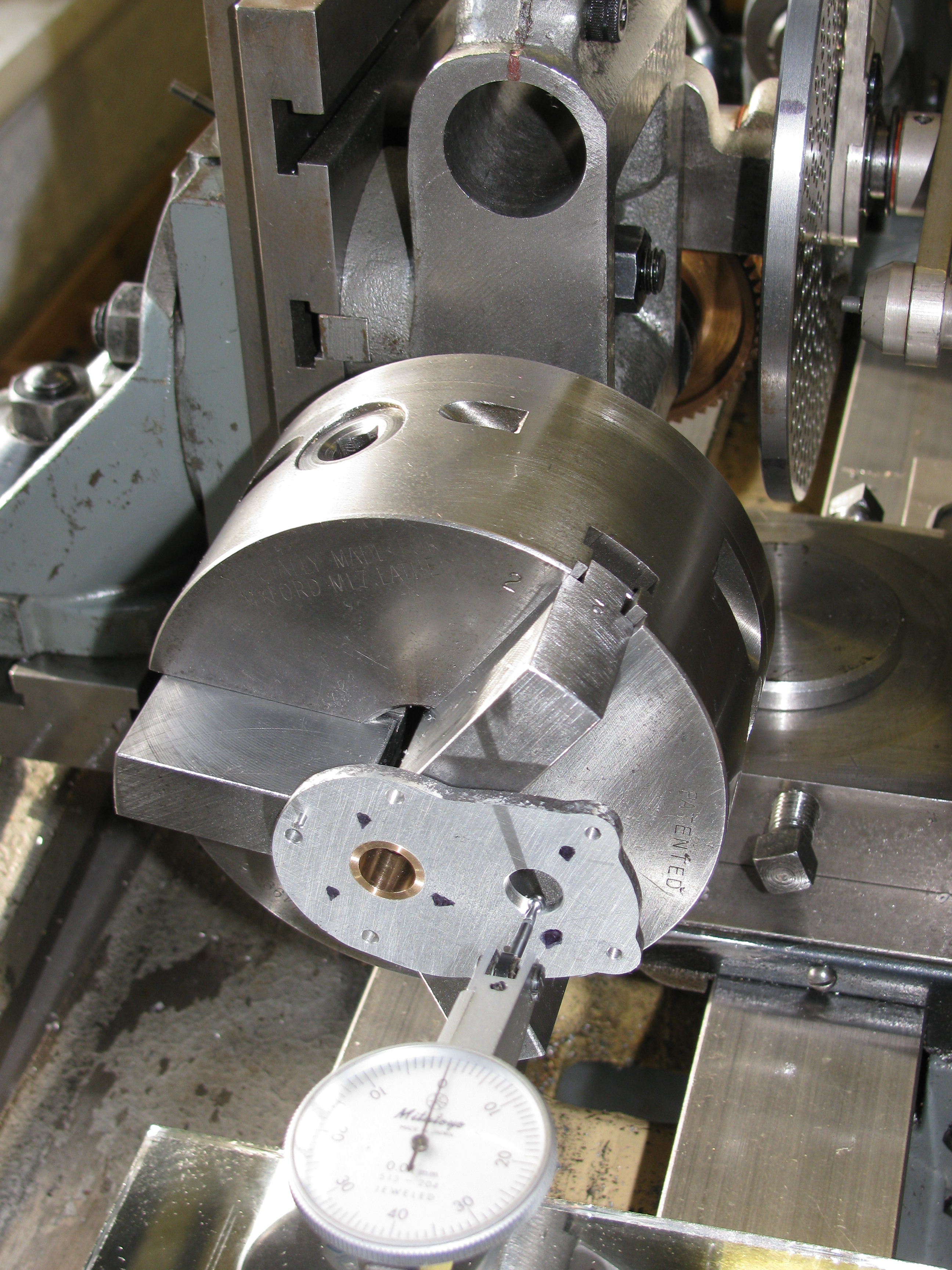
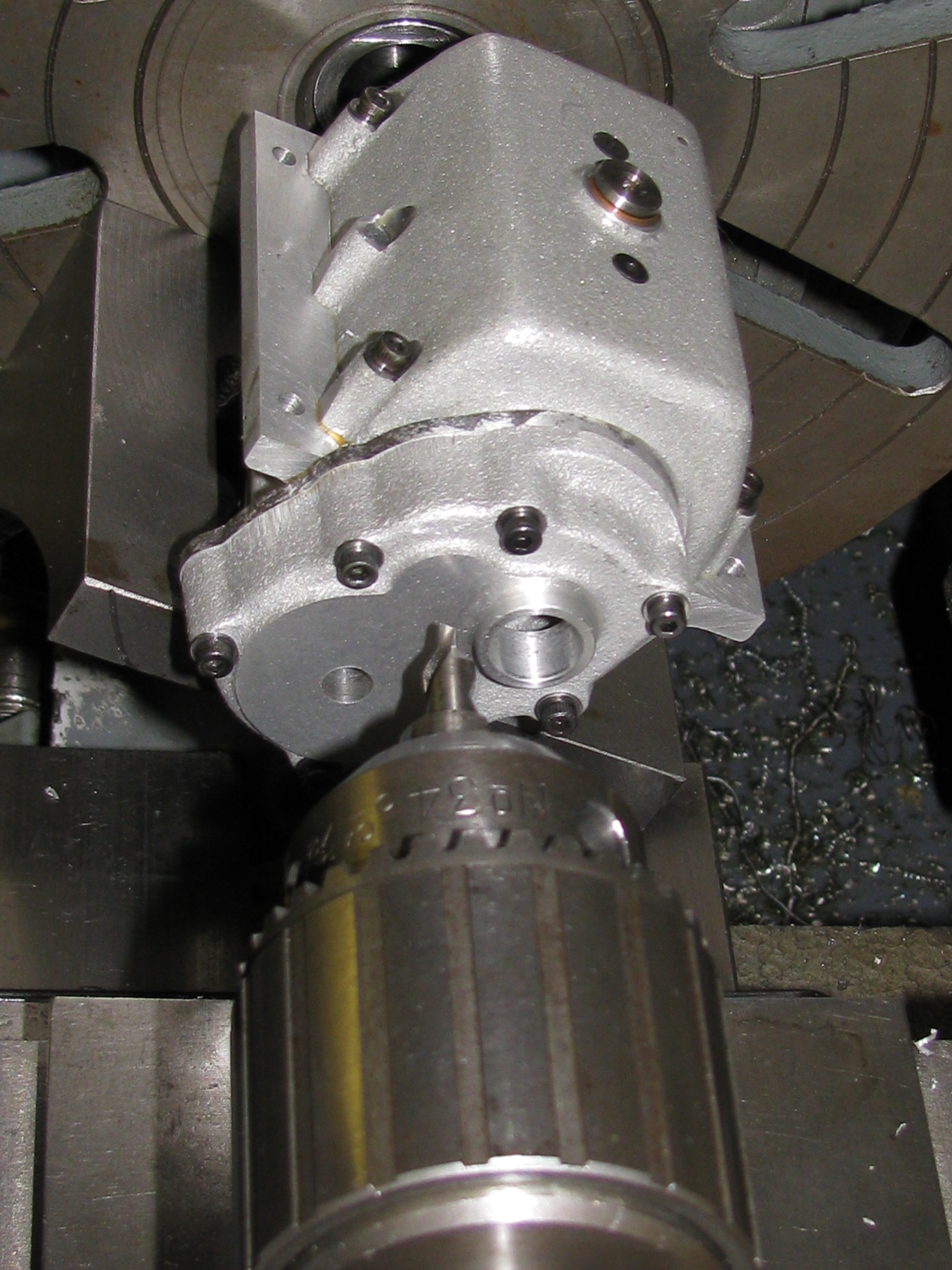
So far, the camshaft hole has only been transferred from the timing case to make sure it is centred across the width of the boss on the case. The final position needs to be found. I made a brass button to fit the camshaft hole in the crankcase, with a ¼″ hole through it, the same as the bearing housing. With the crankcase, sump and bearing housing assembled the holes were lined up, the screws tightened and a bolt put through to hold the button in position. After dismantling I mounted the bearing housing on a truly flat bar by the main bore, and mounted that on the faceplate. As always, I used bits of used brown envelope and surplus business cards to protect the machined surfaces.
It still took a while to get the brass button running true, as the bar was on the limit of its positional range. I had to put flats on the washers on the back of the faceplate because they were interfering with the stiffening ribs. Once it was running true, the button was removed and the temporary bore checked. It was only 0.0035″ out, which I was quite pleased with. I bored the hole out to 0.3755″, though having passed the tool through both ways to get this size it was slightly bell-mouthed on both sides, but fine for a Loctite fit on a nominal size bearing.
It would have been a good idea to fit the Timing Case in place at this stage, to bore it for the ignition timing components, but unfortunately I still have not finished mulling over the design. Instead, the next job is to set the two parts up together to finish the crankshaft bore in the Timing Case.(4 hrs)
2010-11-06 - More drilling
After boring the Timing Case, and without disturbing the job in the chuck, I transferred the chuck to the dividing head for drilling a carefully orientated ring of three oil holes. Quite unnecessary, but it took no longer than careful marking out would have done - these holes come close to the edge of the spigot and I would not want a break-out.
Next, with the 3-jaw chuck back on the lathe spindle, I made up a 0.2″ inch D-bit countersink for the next holes, and then made a stub-mandrel with a short 3⁄8″ diameter shoulder and a 2BA tapped hole.
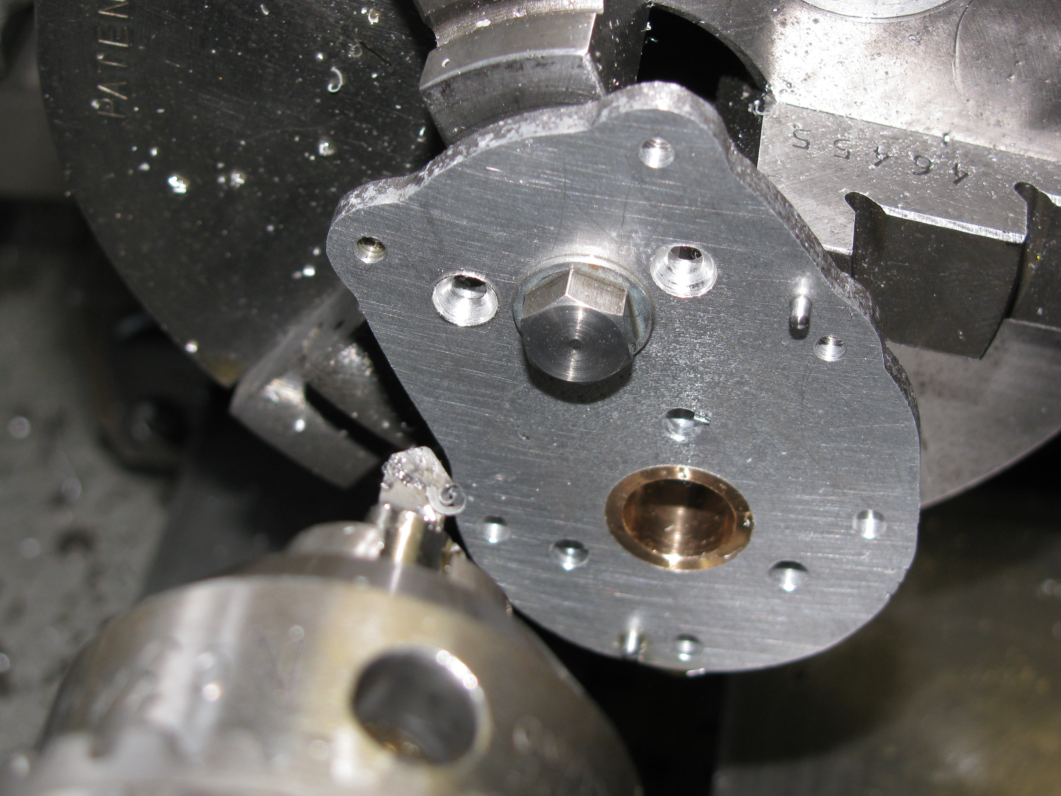
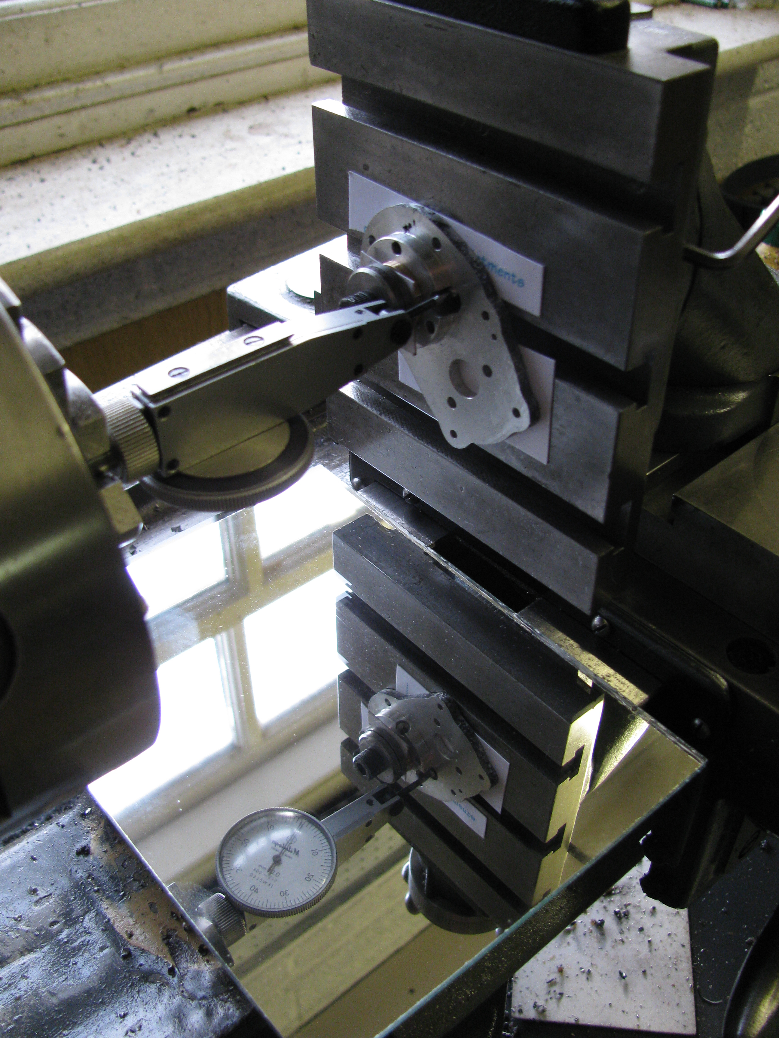
Again transferring the chuck to the dividing head on swivelling vertical slide, setting the plate on the stub-mandrel by the camshaft bearing hole, and setting the angular position from the crankshaft bearing, I drilled the two countersunk holes for additional fixing screws.
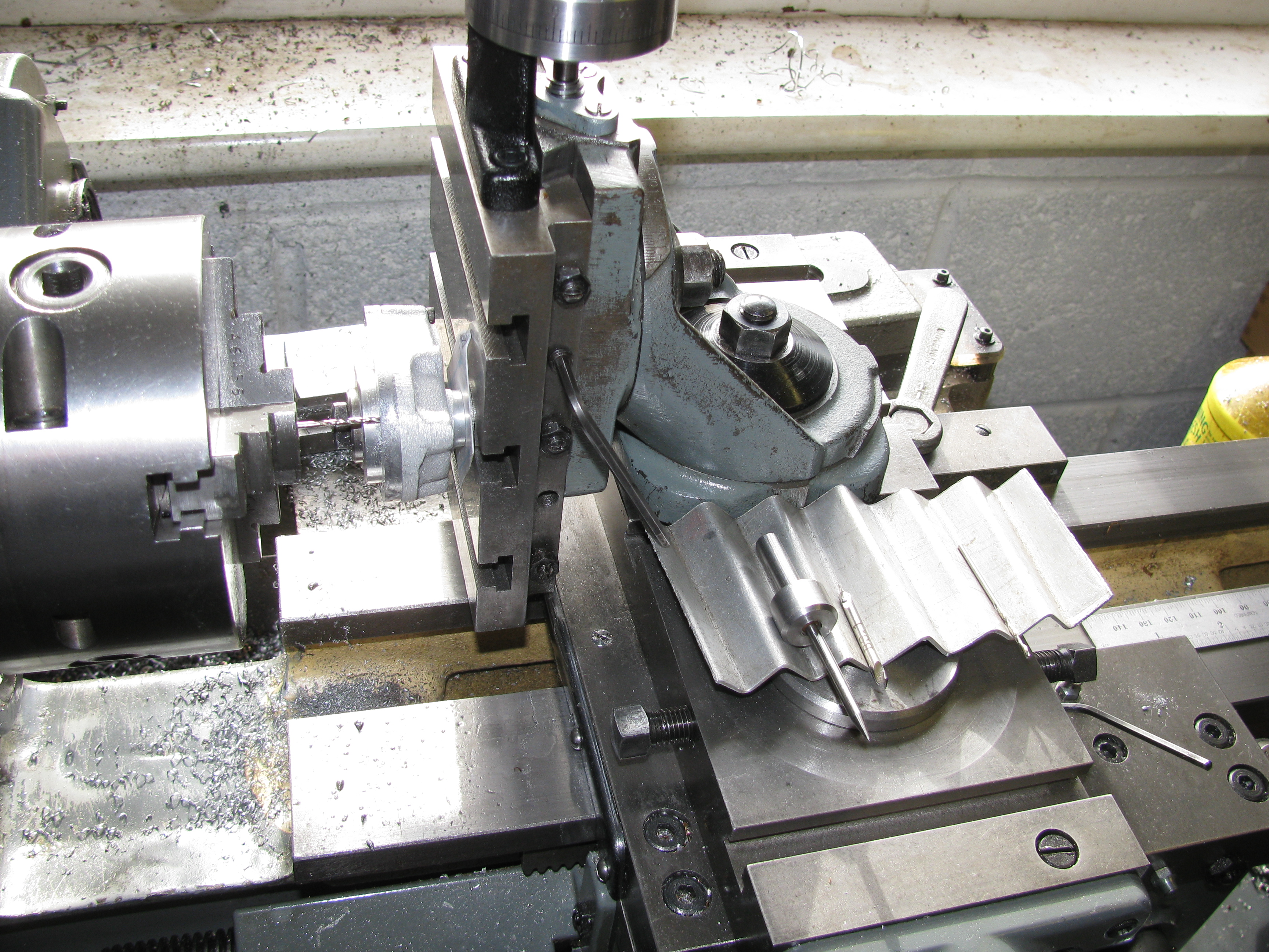
Next I swapped over again, clamping on the stub-mandrel by the bearing bush and setting the orientation from the camshaft hole. With this all set, I changed the vertical slide to a different slot on the cross-slide and set the slide to 75° in plan for drilling the oil hole in the main bearing. I used a sticky pin and rule to line up the hole position 1⁄32″ from the edge of the spigot. I touched the edge with a 1⁄8″ slot drill to make a small flat square to the drill, then put a small centre drill quite deep to form an oil pocket and drilled the rest of the way 2.4 mm. I used the same set-up, but swung round to 45° to drill the oil-hole in the flywheel end bearing. (5¾ hrs)
Next day, I drilled and tapped the crankcase to fit.
2011-11-22 - A hole for the Idler Stud
Having lapped and run the gears a little, I have fixed the final position of the temporary toolmakers' button carrying the idler pinion. The final hole for the idler stud can now be set out from the button. As the Timing Case, Crankcase and Sump all need the same treatment, I decided to set the whole assembly up on an angle plate for accurate boring. This was pretty fiddly to set up on the faceplate, and getting clamps and bolts to fit in tight spaces, arranging clearances, getting everything square, and finally clocking the button to run true all took from mid-morning to lunch time. The idler stud itself is finished, so it can be used as a gauge.
Getting back to the job in the late afternoon I checked the setup, removed the button and centre drilled, drilled, bored and chamfered the hole, going right through the crankcase and sump as well. The result was OK, but not brilliant. I seemed to be able to detect slight taper and roundness errors, even though I ran the lathe at a pretty slow speed to eliminate rocking resulting from the job being not very well balanced. The idler stud was a good enough fit anyway.
Next, without disturbing the set-up, I added the timing case and bored that. With a different piece of material and a different tool this hole was better. I left it quite tight on the stud.
Finally, with the Timing Case and bearing housing removed, I could open out the clearance hole for the nut. This lies partly in the crankcase and partly in the sump. (3¾ hours)
2011-11-23 - Back Facing

With the plate fixed inside out on the vertical slide I clocked the timing stud hole true (using a mirror to help read the dial). I used a slot drill and a d-bit to cut away the locating spigot and just kiss the mounting face to form a spotface to seat the nut.
On assembly, a bit of round material in the idler stud oil hole allows the hole to be oriented downwards and provides a reaction to the nut tightening torque. (1¼ hours)

.
2011-12-10 - Dressing
Work started on cleaning up the cast surfaces. As the two were done as an assembly, this is discussed on the Timing Case page.
2013-01-06 - Assembly
With work on the housing finished, and with final fitting of the timing train to be tackled soon, I though it was time the camshaft bearing was loctited in place. I used a finger-tight bolt through the hole to pull the bush up tight to ensure it was square.
2013-01-09 - Jack Screws

Finally fed up with the difficulty of removing this plate from the crankcase, I decided it was time to put a couple of tapped holes in the plate so that it could be jacked away from the end of the crankcase. I had made such holes in the flywheel end bearing housing right from the start. Putting these holes almost anywhere would work fine but, preferring known locations as usual, I set up on the dividing head by each shaft hole in turn, lined up with an existing fixing hole using a drill shank in the chuck, and then rotated the dividing head to give the desired angular position on the same pitch circle as the fixing holes. Each hole centred, drilled, and counterbored. (about 2 hours)
2013-01-10 - Holes tapped
With the jack-screw holes tapped 8-BA I obviously had to try them out. They make life so much easier. Tidy up. (½ hour)
.