
Tools
Here are some rather random details about some of the tools and jigs I have made while making the engine. Some are general purpose additions to the workshop facilities, and some are very specific to the Seagull project. The amount of detail I have recorded in making them varies enormously.
Cylinder head bolt drilling jig
2014-01-21 - Starting the drilling jig
I cut out a piece of 3⁄16″ mild steel for this jig and milled one side. (1 hour)
2014-01-22 - Drilling jig milling
Today I finished milling the main plate. By compensating for the fact that the cross-slide is not exactly square to the bed, I managed to get the plate pretty accurately square, with the sides parallel to 0.001″ and a maximum of 0.002″ undersize. I cut the side and end fences from some old and rather rusty 15mm by 3mm mild steel and milled the pieces to length, then drilled and tapped the 6 BA fence holes in the plate and finally drilled the clearance holes in the fences.
There will now be an interlude while a second-hand milling machine is acquired, stripped, cleaned-up, repaired and re-commissioned. (It still needs quite a bit work, and a paint job, but I want to get used to it for a while and then decide exactly what else needs doing). Then the first job was to make the base for a DAG Brown pattern Small Drill Sharpening Tool. (3¾ hours)
2014-03-20 - Preparing the drilling jig
After a discussion on a couple of forums I decided that the drilling jig would be most accurate if the holes were made for hardened bushes, one for tapping size and one for clearance size. I also decided that if I was going to all this trouble I should position the holes using the toolmaker's button method. I ground up a small boring bit for the purpose and then stamped the top side of the jig plate. (½ hour)
2014-03-23 - Drilling the drilling jig
I marked out the initial hole positions as honed the sides of the jig to remove the 0.001″ taper and to improve the squareness. I drilled the holes on the milling machine. I think the Y-axis dial moved, as some of the holes ended up a mile out; a good thing I decided on buttons for final position. I tapped the holes, set the button for the first hole using slip gauges and the surface plate in the usual way, and set the job up on the lathe faceplate with the button clocked true. I opened the hole out with a 5⁄32″ slot drill to avoid following the tapped hole, and then bored and reamed the hole 3⁄16 ″. The boring tool evidently was not right as it would only cut on the outfeed. I repeated the process for the second hole. (3½ hours)
2014-03-24 - Boring the rest of the holes
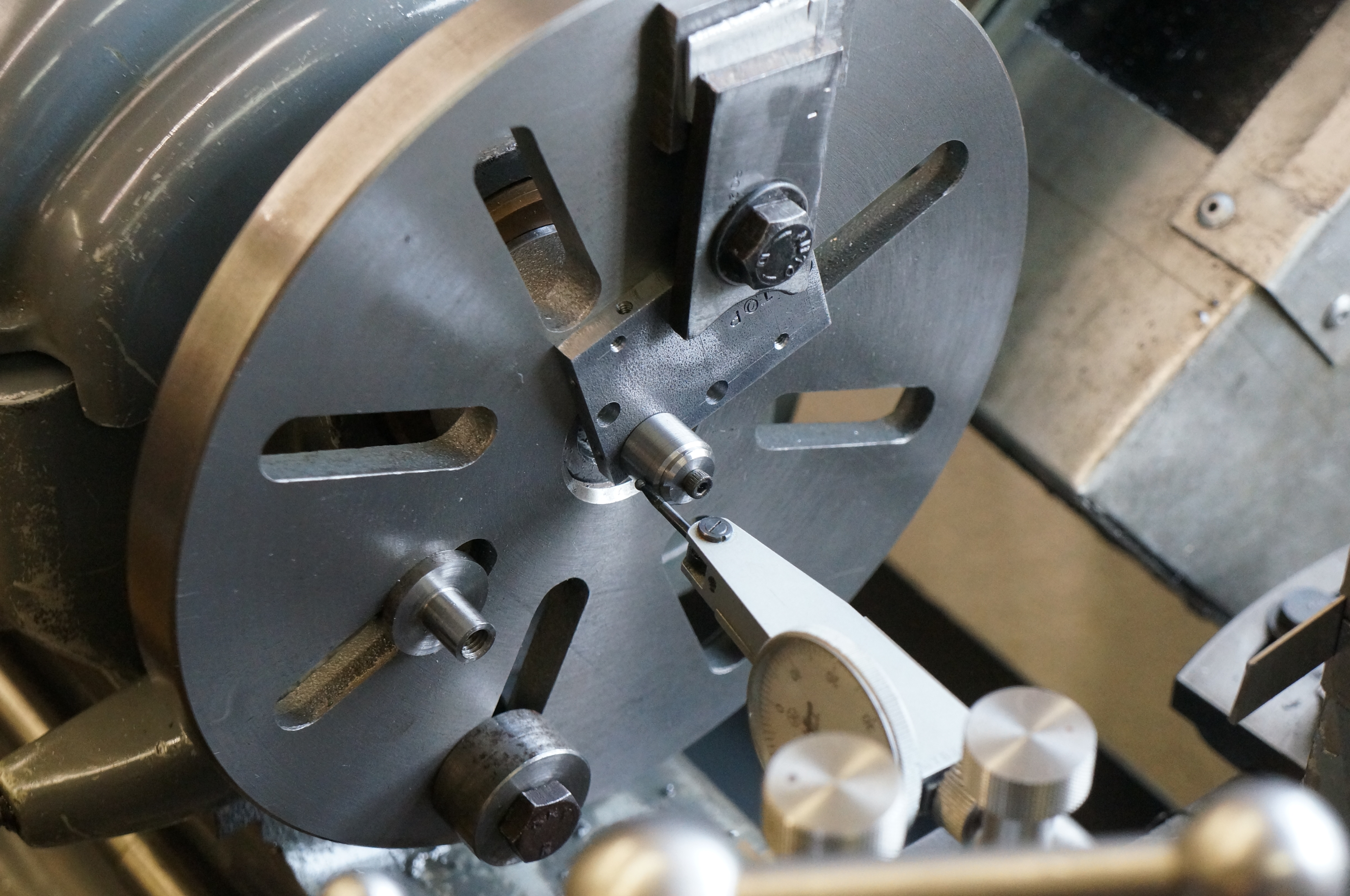
Today I bored all the remaining six holes, setting up each one with the toolmaker's button on the surface plate and then re-mounting on the faceplate. Note the stub is still in place on the faceplate for mounting the con-rods for machining the little ends, as I have yet to make a satisfactory job of them. (4 hours)
2014-03-25 - Re-working two holes
I had forgotten that I intended to move the holes by the combustion chambers out a bit. There is only room for another 1⁄64″ between centres, but even this much will make a difference. I had to set the toolmaker's button with a washer and nut behind. I opened the holes to a little over 7⁄32″ to completely re-machine the old misplaced hole. I will have to either sleeve them back down to 3⁄16, or make special drilling bushes to fit. Later, I machined the drilling bushes from silver steel, one drilled 2.2 mm for tapping and the other 2.8 mm, which is nominal size for 6 BA. I will try drilling the holes like this first as it will give the best alignment of the parts, short of dowelling, but if the drilling is not perfectly accurate I may have to open the holes out a shade to provide enough clearance. (3¾ hours)
.